EP2014018B1 - Police de résolution configurable pour défauts de caractéristiques de commutation de données - Google Patents
Police de résolution configurable pour défauts de caractéristiques de commutation de données Download PDFInfo
- Publication number
- EP2014018B1 EP2014018B1 EP06832231A EP06832231A EP2014018B1 EP 2014018 B1 EP2014018 B1 EP 2014018B1 EP 06832231 A EP06832231 A EP 06832231A EP 06832231 A EP06832231 A EP 06832231A EP 2014018 B1 EP2014018 B1 EP 2014018B1
- Authority
- EP
- European Patent Office
- Prior art keywords
- feature
- features
- failure
- policy
- interfaces
- Prior art date
- Legal status (The legal status is an assumption and is not a legal conclusion. Google has not performed a legal analysis and makes no representation as to the accuracy of the status listed.)
- Not-in-force
Links
Images

Classifications
-
- H—ELECTRICITY
- H04—ELECTRIC COMMUNICATION TECHNIQUE
- H04L—TRANSMISSION OF DIGITAL INFORMATION, e.g. TELEGRAPHIC COMMUNICATION
- H04L12/00—Data switching networks
- H04L12/66—Arrangements for connecting between networks having differing types of switching systems, e.g. gateways
Definitions
- the present invention relates generally to communication systems, and specifically to configuration of service features provided on data switch platforms.
- Routers are data switches that handle connections between different networks.
- a router identifies the addresses on data packets passing through the switch, determines which route the transmission should take, and then forwards the packets to their destinations.
- Routers typically operate at the network layer (Layer 3 in the well-known Open Systems Interconnect [OSI] model), using Internet Protocol (IP) addressing and routing conventions.
- OSI Open Systems Interconnect
- IP Internet Protocol
- Advanced routers currently on the market not only route packets, but also offer a variety of additional service features.
- Cisco Systems® Inc. (San Jose, California) offers the following features in its 12000 Series Routers and Catalyst 6500 Series Switches:
- US-A-2005/180429 describes a multi-service network switch capable of providing multiple network services from a single platform.
- the switch incorporates a distributed packet forwarding architecture where each of the various cards is capable of making independent forwarding decisions.
- the switch further allows for dynamic resource management for dynamically assigning modem and ISDN resources to an incoming call.
- the switch may also include fault management features to guard against points of failure within the switch.
- the switch further allows the partitioning of the switch into multiple virtual routers where each virtual router has its own set of resources and a routing table. Each virtual router is further partitioned into virtual private networks for further controlling access to the network.
- the switch supports policy based routing where specific routing paths are selected based on a domain name, a telephone number or the like.
- the switch also provides tiered access of the Internet by defining the quality of access levels to each incoming connection request.
- US 5260945 describes a distributed computer system having components which may fail intermittently.
- a fault monitor coupled to one component, detects whether that component is working. Whenever the fault monitor detects that the component has failed, a status filter transmits a broken signal and whenever the fault monitor detects that the component has changed from a broken to working status, the status filter transmits a working signal after a recovery time interval.
- US-A-2004/146062 discloses a system that has an IP network card that has a redundancy configuration register, an interface and redundancy mapping logic.
- the redundancy configuration register stores card configuration data.
- the interface receives slot active signals from other cards.
- the redundancy mapping logic is coupled to the register and interface and maps a packet to a slot having an active card based on the data in the register, an address in the packet and received slot active signals.
- US-A-2002/145981 discloses a method and system for maintaining a traffic service level for data communicated by a computer network having a source.
- the computer network is connected to at least one of many networks, where each of the many networks includes a number of paths for transporting the data communicated to a destination.
- the traffic service level associated with one of the paths between the source and the destination is monitored. It is then determined whether the traffic service level associated with the path meets one or more performance metrics. If the flow of data communicated over the monitored path fails to meet at least one of the performance metrics, then a service level violation is indicated and an alternative path is selected to resolve the violation.
- the present invention aims to provide alternative communication methods and communication apparatus having fault tolerant features.
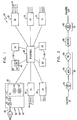
- Fig. 1 is a block diagram that schematically illustrates a service-enabled router 20, in accordance with an embodiment of the present invention.
- the router comprises multiple line cards 22, each having one or more interfaces 24 for connecting to communication lines.
- the line cards are interconnected via a switching core, which typically has the form of a switch fabric 26.
- the router may also comprises one or more service cards 28, also connected to fabric 26, for applying certain services to data packets processed by the router, as described hereinbelow.
- packets are received in line cards 22 by a Layer 1 (physical layer) processor 30 and are then processed by a Layer 2 (medium access control [MAC]) processor 32 and a Layer 3 (network layer) processor 34, as are known in the art.
- a given interface 24 may serve multiple virtual sub-interfaces 36, such as Virtual Local Area Networks (VLANs).
- the interface may be a virtual interface, such as a tunnel interface, which is not related to a particular physical interface.
- Layer 3 processor 34 may serve as a service processor, to apply additional service features to each packet.
- line card 22 may comprise a separate service processor, not shown in the figure, for this purpose.
- line card 22 may comprise a separate service processor, not shown in the figure, for this purpose.
- Exemplary features shown in Fig 1 include an ACL (Access Control List) filter 40 and a QoS controller 42. After applying the appropriate services to the packet, the ingress line card passes the packet to fabric 26.
- ACL Access Control List
- packets may be subject to additional processing features that are performed on service cards 28, rather than line cards 22.
- packets may be subject to additional processing features that are performed on service cards 28, rather than line cards 22.
- some (or all) packets are passed by fabric 26 to a firewall 46 on service card 28.
- This firewall is implemented by a service processor 44 on the service card.
- Fabric 26 then passes the packets to the appropriate egress line card, which may apply additional processing features to the packets before transmitting them onward via one of interfaces 24.
- router 20 in Fig. 1 and the order of processing operations in the figure are shown here solely by way of example, to illustrate one possible implementation of the principles of the present invention. Alternative router and service feature configurations will be apparent to those skilled in the art and are considered to be within the scope of the present invention.
- the functional blocks identified within the router are presented for the sake of conceptual clarity and do not necessarily reflect the actual hardware or software structure of the router. Rather, the functions of an individual block that is shown in the figure may be divided among multiple physical blocks in an actual implementation of the router or, conversely, a number of different blocks may be combined into the functions of a single processor.
- the elements of router 20 may be implemented using dedicated or programmable hardware elements or, alternatively, in software running on an embedded microprocessor or computing platform. This software may be downloaded to the router in electronic form, over a network, for example, or it may alternatively be provided on tangible media, such as optical, magnetic, or electronic memory media.
- Fig. 2 is a flow chart that schematically illustrates processing features applied to packets transferred through router 20, in accordance with an embodiment of the present invention.
- the features are arranged in an ingress feature chain 50 and an egress feature chain 52.
- Both the ingress and egress feature chains may be defined individually for each ingress interface (or sub-interface) and egress interface (or sub-interface) in the router.
- the operator of router 20 may provide different sets of features to different users, who are connected to different, respective interfaces of the router.
- the order of features may also be varied from one interface to another.
- different feature chains may be defined for different traffic directions (ingress or egress).
- ingress feature chain 50 comprises an ingress ACL filter 54, a QoS controller 56, and a firewall 58.
- the ACL filter is a collection of permit and deny conditions that apply to IP addresses of incoming packets.
- Packets that successfully pass through the ingress feature chain are forwarded by a routing process 60 to the egress path.
- egress chain 52 comprises only a single feature: an egress ACL filter 62.
- the features in the ingress and egress feature chains may be implemented either in line cards 22 or in service cards 28, depending on the configuration and capabilities of the router.
- router 20 is configured with redundant components, so that service features can be maintained even if the component running a particular feature fails. In some cases, however, there may be no backup available. For example, multiple failures may occur concurrently, or the service provider operating the router may have chosen to reduce cost by reducing (or eliminating) redundancy. In such events, router 20 applies a predetermined failure policy in deciding how to respond to the failure. Embodiments of the present invention permit the failure policy to be configured and applied individually for each interface 24 or sub-interface 36 of the router and each feature on this interface, as described hereinbelow.
- Fig. 3 is a flow chart that schematically illustrates a method for defining and implementing failure policies in router 20, in accordance with an embodiment of the present invention.
- Feature chains are initially defined for each interface 24 (and possibly for some or all sub-interfaces 36) in the router, at a feature definition step 70. Additionally or alternatively, feature chains may be defined for certain traffic classes and/or specific protocols. These class- or protocol-specific feature chains may extend across multiple interfaces 24 or across all the interfaces.
- a failure policy is then defined for each feature (or feature type) in each feature chain, at a failure definition step 72.
- the same feature appearing in feature chains of different interfaces or sub-interfaces may have a different associated failure policy in each chain.
- the failure policy may act on the whole feature chain, for example, by changing the interface state, altering the behavior of other service features in the chain, or adding and/or removing service features.
- Exemplary failure policies include the following:
- policies are listed solely by way of example, and other policies may similarly be used.
- router 20 is operational and proceeds to route packets through interfaces 24, subject to the applicable services specified by the feature chains, at a routing step 84. Normal routing continues in this manner unless and until a failure event is detected in one of the service features, at a failure detection step 86.
- the appropriate processor in the router determines whether there is a redundant backup component available to take the place of the failed feature, at a backup availability checking step 88. If so, the backup component is activated, at a backup activation step 90.
- the interface (or interfaces) affected by the failure may then continue operation without change to the feature chain.
- the router implements the predefined failure policy, at a policy invocation step 92.
- the failed service may be bypassed, the affected interface may be shut down, packets on the interface may be dropped, or other actions may be taken, such as those listed above.
- operation of the affected interface typically returns to normal.
Landscapes
- Engineering & Computer Science (AREA)
- Computer Networks & Wireless Communication (AREA)
- Signal Processing (AREA)
- Data Exchanges In Wide-Area Networks (AREA)
- Hardware Redundancy (AREA)
- Logic Circuits (AREA)
- Electronic Switches (AREA)
- Test And Diagnosis Of Digital Computers (AREA)
- Monitoring And Testing Of Exchanges (AREA)
- Multi Processors (AREA)
Claims (19)
- Procédé pour la communication, comprenant :l'association de chaînes de fonctions respectives à une pluralité d'interfaces (24) d'un commutateur de données (20), les chaînes de fonctions comprenant des fonctions de service ;la définition (72) d'une politique d'échec respective pour chacune d'une ou plusieurs des fonctions de service dans chacune des chaînes de fonctions ;la détection (86) d'un échec dans une fonction de service dans une chaîne de fonctions associée à une des interfaces (24) ; etle routage de paquets de données par l'intermédiaire du commutateur de données en appliquant (92), en réponse à l'échec, la politique d'échec respective à l'une des interfaces (24).
- Procédé selon la revendication 1, dans lequel la pluralité des interfaces (24) comprend au moins des première et seconde interfaces, et dans lequel l'association des chaînes de fonctions respectives comprend l'association respective de première et seconde chaînes de fonctions différentes aux première et seconde interfaces (24).
- Procédé selon la revendication 1, dans lequel la pluralité des interfaces (24) comprend au moins des première et seconde interfaces, et dans lequel la définition (72) de la politique d'échec respective comprend la définition de première et seconde politiques d'échec différentes pour les fonctions de service dans les chaînes de fonctions associées aux première et seconde interfaces (24).
- Procédé selon la revendication 3, dans lequel les chaînes de fonctions associées aux première et seconde interfaces (24) comprennent respectivement des première et seconde chaînes de fonctions, toutes deux comprenant une fonction de service commune, et
dans lequel la définition (72) de première et seconde politiques d'échec différentes comprend l'affectation de la première politique d'échec à la fonction de service commune dans la première chaîne de fonctions et l'affectation de la seconde politique d'échec à la fonction de service commune dans la seconde chaîne de fonctions. - Procédé selon la revendication 1, dans lequel les fonctions de service sont sélectionnées dans une liste comprenant des fonctions de Qualité de Service (QoS), des fonctions de réseau privé virtuel (VPN), des fonctions de sécurité, des fonctions de comptabilité, des fonctions de statistiques et de facturation, des fonctions de flux de réseau, des fonctions de routage, des fonctions de redirection de trafic, des fonctions d'interception, des fonctions de traduction d'adresses de réseau (NAT), des fonctions de reconnaissance d'application et des fonctions d'équilibrage de charge.
- Procédé selon l'une quelconque des revendications 1 à 5, dans lequel la définition (72) de la politique d'échec respective comprend la définition d'une politique d'abandon de trafic ou la définition d'une politique de contournement de service ou la définition d'une politique d'arrêt d'interface ou la définition d'une politique d'arrêt de protocole ou la définition d'une politique de changement de chaîne de fonctions, de préférence dans lequel la chaîne de fonctions comprend un pare-feu, et dans lequel la politique de changement de chaîne de fonctions comprend l'activation d'un filtrage de liste de contrôle d'accès (ACL) en réponse à l'échec du pare-feu ou dans lequel la définition de la politique d'échec respective comprend la définition d'une politique de changement de coût de route.
- Procédé selon l'une quelconque des revendications 1 à 5, dans lequel l'application (92) de la politique d'échec respective comprend l'invocation d'un composant redondant comme un secours pour l'échec de service lorsque le composant redondant est disponible, et l'application de la politique d'échec respective lorsqu'il n'y a pas de composant redondant disponible.
- Procédé selon l'une quelconque des revendications 1 à 5, dans lequel l'association des chaînes de fonctions respectives comprend l'association de chaînes de fonctions respectives différentes à des sous-interfaces différentes d'une interface donnée, et dans lequel la définition de la politique d'échec respective comprend la définition de politiques d'échec respectives différentes pour les fonctions de service dans les chaînes de fonctions associées aux sous-interfaces différentes.
- Procédé selon l'une quelconque des revendications 1 à 5, dans lequel l'association des chaînes de fonctions respectives comprend la définition d'une chaîne de fonctions de classe pour l'application à une classe de trafic à travers au moins un sous-ensemble de la pluralité d'interfaces (24).
- Appareil pour la communication, comprenant :un moyen pour associer des chaînes de fonctions respectives à une pluralité d'interfaces (24) d'un commutateur de données (20), les chaînes de fonctions comprenant des fonctions de service ;un moyen pour définir une politique d'échec respective pour chacune d'une ou plusieurs des fonctions de service dans chacune des chaînes de fonctions ;un moyen pour détecter un échec dans une fonction de service dans une chaîne de fonctions associée à une des interfaces (24) ; etun moyen pour router des paquets de données par l'intermédiaire du commutateur de données (20) en appliquant, en réponse à l'échec, la politique d'échec respective à l'une des interfaces (24).
- Appareil selon la revendication 10, dans lequel la pluralité des interfaces (24) comprend au moins des première et seconde interfaces, et dans lequel les chaînes de fonctions comprennent des première et seconde chaînes de fonctions différentes qui sont associées respectivement aux première et seconde interfaces (24).
- Appareil selon la revendication 10, dans lequel la pluralité des interfaces (24) comprend au moins des première et seconde interfaces, et dans lequel ledit moyen pour définir est agencé pour définir des première et seconde politiques d'échec différentes pour les fonctions de service dans les chaînes de fonctions associées aux première et seconde interfaces (24), de préférence dans lequel les chaînes de fonctions associées aux première et seconde interfaces (24) comprennent respectivement des première et seconde chaînes de fonctions, toutes deux comprenant une fonction de service commune, et
dans lequel la première politique d'échec est affectée à la fonction de service commune dans la première chaîne de fonctions et la seconde politique d'échec, différente de la première politique d'échec, est affectée à la fonction de service commune dans la seconde chaîne de fonctions. - Appareil selon la revendication 10, dans lequel les fonctions de service sont sélectionnées dans une liste comprenant des fonctions de Qualité de Service (QoS), des fonctions de réseau privé virtuel (VPN), des fonctions de sécurité, des fonctions de comptabilité, des fonctions de statistiques et de facturation, des fonctions de flux de réseau, des fonctions de routage, des fonctions de redirection de trafic, des fonctions d'interception, des fonctions de traduction d'adresses de réseau (NAT), des fonctions de reconnaissance d'application et des fonctions d'équilibrage de charge.
- Appareil selon l'une quelconque des revendications 10 à 13, dans lequel la politique d'échec comprend une politique d'abandon de trafic ou dans lequel la politique d'échec comprend une politique de contournement de service ou dans lequel la politique d'échec comprend une politique d'arrêt d'interface ou dans lequel la politique d'échec comprend une politique d'arrêt de protocole ou dans lequel la politique d'échec comprend une politique de changement de chaîne de fonctions ou dans lequel la politique d'échec comprend une politique de changement de coût de route.
- Appareil selon l'une quelconque des revendications 10 à 14, comprenant au moins un processeur de service qui est agencé pour invoquer un composant redondant comme un secours pour l'échec de service lorsque le composant redondant est disponible, et pour appliquer la politique d'échec respective lorsqu'il n'y a pas de composant redondant disponible.
- Appareil selon l'une quelconque des revendications 10 à 15, dans lequel une ou plusieurs des interfaces (24) sont configurées pour supporter de multiples sous-interfaces, et dans lequel le moyen pour associer est agencé pour associer des chaînes de fonctions respectives différentes à des sous-interfaces différentes d'une interface donnée (24), et pour accepter une définition de politiques d'échec respectives différentes pour les fonctions de service dans les chaînes de fonctions associées aux sous-interfaces différentes.
- Appareil selon l'une quelconque des revendications 10 à 16, comprenant un moyen pour appliquer une chaîne de fonctions de classe à une classe de trafic à travers au moins un sous-ensemble de la pluralité d'interfaces (24).
- Procédé pour la communication, comprenant :l'association de chaînes de fonctions respectives à une pluralité de classes de trafic traitées par un commutateur de données (20), les chaînes de fonctions comprenant des fonctions de service ;la définition d'une politique d'échec respective pour chacune d'une ou plusieurs des fonctions de service dans chacune des chaînes de fonctions ;la détection d'un échec dans une fonction de service dans une chaîne de fonctions associée à une des classes de trafic ; etle routage de paquets de données par l'intermédiaire du commutateur de données (20) en appliquant, en réponse à l'échec, la politique d'échec respective à l'une des classes de trafic.
- Appareil pour la communication, comprenant :un moyen pour associer des chaînes de fonctions respectives à une pluralité de classes de trafic traitées par un commutateur de données (20), les chaînes de fonctions comprenant des fonctions de service ;un moyen pour définir une politique d'échec respective pour chacune d'une ou plusieurs des fonctions de service dans chacune des chaînes de fonctions ;un moyen pour détecter un échec dans une fonction de service dans une chaîne de fonctions associée à une des classes de trafic ; etun moyen pour router des paquets de données par l'intermédiaire du commutateur de données (20) en appliquant, en réponse à l'échec, la politique d'échec respective à l'une des classes de trafic.
Applications Claiming Priority (2)
| Application Number | Priority Date | Filing Date | Title |
|---|---|---|---|
| US11/409,475 US7877505B1 (en) | 2006-04-21 | 2006-04-21 | Configurable resolution policy for data switch feature failures |
| PCT/IL2006/001429 WO2007122603A2 (fr) | 2006-04-21 | 2006-12-12 | Police de résolution configurable pour défauts de caractéristiques de commutation de données |
Publications (3)
| Publication Number | Publication Date |
|---|---|
| EP2014018A2 EP2014018A2 (fr) | 2009-01-14 |
| EP2014018A4 EP2014018A4 (fr) | 2010-06-09 |
| EP2014018B1 true EP2014018B1 (fr) | 2011-08-03 |
Family
ID=38625406
Family Applications (1)
| Application Number | Title | Priority Date | Filing Date |
|---|---|---|---|
| EP06832231A Not-in-force EP2014018B1 (fr) | 2006-04-21 | 2006-12-12 | Police de résolution configurable pour défauts de caractéristiques de commutation de données |
Country Status (5)
| Country | Link |
|---|---|
| US (1) | US7877505B1 (fr) |
| EP (1) | EP2014018B1 (fr) |
| CN (1) | CN101496365B (fr) |
| AT (1) | ATE519299T1 (fr) |
| WO (1) | WO2007122603A2 (fr) |
Families Citing this family (5)
| Publication number | Priority date | Publication date | Assignee | Title |
|---|---|---|---|---|
| US8630287B2 (en) * | 2010-08-20 | 2014-01-14 | Marvell Israel (M.I.S.L) Ltd. | Multiple core network device with core redundancy |
| US20130332596A1 (en) * | 2012-06-11 | 2013-12-12 | James O. Jones | Network traffic tracking |
| EP2808846A1 (fr) * | 2013-05-31 | 2014-12-03 | Cabeco AB | Dispositif et procédé pour diagnostiquer les défauts dans les systèmes électroniques |
| CN104735047B (zh) * | 2014-12-02 | 2018-04-27 | 重庆晴彩科技有限公司 | 一种混合模式网络物理链路应急智能切换系统 |
| US12255811B2 (en) * | 2023-07-31 | 2025-03-18 | Nutanix, Inc. | Fallback-aware policy-based routing |
Family Cites Families (18)
| Publication number | Priority date | Publication date | Assignee | Title |
|---|---|---|---|---|
| US5260945A (en) | 1989-06-22 | 1993-11-09 | Digital Equipment Corporation | Intermittent component failure manager and method for minimizing disruption of distributed computer system |
| US6393548B1 (en) | 1997-02-14 | 2002-05-21 | Advanced Micro Devices, Inc. | Variable 16 or 32 bit PCI interface which supports steering and swapping of data |
| US6078953A (en) * | 1997-12-29 | 2000-06-20 | Ukiah Software, Inc. | System and method for monitoring quality of service over network |
| CN1328885C (zh) | 1999-02-23 | 2007-07-25 | 阿尔卡塔尔互联网运行公司 | 具有接入质量的多业务网络交换机 |
| US7222147B1 (en) * | 2000-05-20 | 2007-05-22 | Ciena Corporation | Processing network management data in accordance with metadata files |
| US7349960B1 (en) * | 2000-05-20 | 2008-03-25 | Ciena Corporation | Throttling distributed statistical data retrieval in a network device |
| US20020176131A1 (en) * | 2001-02-28 | 2002-11-28 | Walters David H. | Protection switching for an optical network, and methods and apparatus therefor |
| US20020184487A1 (en) * | 2001-03-23 | 2002-12-05 | Badamo Michael J. | System and method for distributing security processing functions for network applications |
| US7269157B2 (en) | 2001-04-10 | 2007-09-11 | Internap Network Services Corporation | System and method to assure network service levels with intelligent routing |
| US7844696B2 (en) | 2001-06-27 | 2010-11-30 | Arbor Networks, Inc. | Method and system for monitoring control signal traffic over a computer network |
| CN1414757A (zh) * | 2002-05-08 | 2003-04-30 | 华为技术有限公司 | 自动按序配置访问控制列表规则的方法及其应用 |
| US6947375B2 (en) | 2003-01-27 | 2005-09-20 | Nokia Inc. | System and method for network card switchovers in an IP network |
| CN1319326C (zh) * | 2003-04-01 | 2007-05-30 | 华为技术有限公司 | 一种基于承诺接入速率的带宽统计复用方法 |
| CN1728679A (zh) * | 2004-07-31 | 2006-02-01 | 华为技术有限公司 | 路由器配置方法 |
| US7606147B2 (en) * | 2005-04-13 | 2009-10-20 | Zeugma Systems Inc. | Application aware traffic shaping service node positioned between the access and core networks |
| US8151339B2 (en) * | 2005-12-23 | 2012-04-03 | Avaya, Inc. | Method and apparatus for implementing filter rules in a network element |
| US8730954B2 (en) * | 2008-09-11 | 2014-05-20 | Juniper Networks, Inc. | Methods and apparatus related to any-to-any connectivity within a data center |
| US8340088B2 (en) * | 2008-09-11 | 2012-12-25 | Juniper Networks, Inc. | Methods and apparatus related to a low cost data center architecture |
-
2006
- 2006-04-21 US US11/409,475 patent/US7877505B1/en not_active Expired - Fee Related
- 2006-12-12 CN CN2006800542988A patent/CN101496365B/zh not_active Expired - Fee Related
- 2006-12-12 EP EP06832231A patent/EP2014018B1/fr not_active Not-in-force
- 2006-12-12 AT AT06832231T patent/ATE519299T1/de not_active IP Right Cessation
- 2006-12-12 WO PCT/IL2006/001429 patent/WO2007122603A2/fr not_active Ceased
Also Published As
| Publication number | Publication date |
|---|---|
| US7877505B1 (en) | 2011-01-25 |
| WO2007122603A2 (fr) | 2007-11-01 |
| EP2014018A4 (fr) | 2010-06-09 |
| CN101496365A (zh) | 2009-07-29 |
| ATE519299T1 (de) | 2011-08-15 |
| WO2007122603A3 (fr) | 2009-04-16 |
| CN101496365B (zh) | 2013-08-28 |
| EP2014018A2 (fr) | 2009-01-14 |
Similar Documents
| Publication | Publication Date | Title |
|---|---|---|
| EP1690403B1 (fr) | Pare-feu bimodal | |
| US7224668B1 (en) | Control plane security and traffic flow management | |
| US10084751B2 (en) | Load balancing among a cluster of firewall security devices | |
| JP4886788B2 (ja) | 仮想ネットワーク、データ・ネットワーク・システム、コンピュータ・プログラム、およびコンピュータ・プログラムを運用する方法 | |
| US9270639B2 (en) | Load balancing among a cluster of firewall security devices | |
| US7941837B1 (en) | Layer two firewall with active-active high availability support | |
| US20040131059A1 (en) | Single-pass packet scan | |
| EP3605968A1 (fr) | Modèle de redondance de passerelle d'applications dynamiques n:1 | |
| US20040148520A1 (en) | Mitigating denial of service attacks | |
| WO2003015374A1 (fr) | Circulation controlee des informations entre les communautes a travers un coupe-feu | |
| US7394756B1 (en) | Secure hidden route in a data network | |
| US8479275B1 (en) | Secure high-throughput data-center network employing routed firewalls | |
| US7877505B1 (en) | Configurable resolution policy for data switch feature failures | |
| CN110071905B (zh) | 用于提供连接的方法、边界网络以及ip服务器 | |
| Vadivelu et al. | Design and performance analysis of complex switching networks through VLAN, HSRP and link aggregation | |
| CN116170389B (zh) | 业务容器引流方法、系统及计算机集群 | |
| US20050086524A1 (en) | Systems and methods for providing network security with zero network footprint | |
| KR20030018018A (ko) | 패킷 컨트롤 시스템과 방법 | |
| CN119299407A (zh) | 一种报文状态检查方法、装置、交换机设备及存储介质 | |
| CN108810001A (zh) | 一种基于sdn的安全服务控制系统及方法 | |
| Works | Unicast Reverse Path Forwarding | |
| Headquarters | Cisco IOS Mobile Wireless Radio Access Networking Command Reference | |
| HK1083907A1 (zh) | 虚拟专用网(vpn)和防火墙的集成系统 | |
| HK1083907B (en) | Vpn and firewall integrated system |
Legal Events
| Date | Code | Title | Description |
|---|---|---|---|
| PUAI | Public reference made under article 153(3) epc to a published international application that has entered the european phase |
Free format text: ORIGINAL CODE: 0009012 |
|
| 17P | Request for examination filed |
Effective date: 20081118 |
|
| AK | Designated contracting states |
Kind code of ref document: A2 Designated state(s): AT BE BG CH CY CZ DE DK EE ES FI FR GB GR HU IE IS IT LI LT LU LV MC NL PL PT RO SE SI SK TR |
|
| AX | Request for extension of the european patent |
Extension state: AL BA HR MK RS |
|
| RIN1 | Information on inventor provided before grant (corrected) |
Inventor name: CHATTERJEE, SIMON Inventor name: OZ, DORON Inventor name: ALTSHULER, SAREL |
|
| R17D | Deferred search report published (corrected) |
Effective date: 20090416 |
|
| RIC1 | Information provided on ipc code assigned before grant |
Ipc: H04L 12/66 20060101AFI20090422BHEP |
|
| A4 | Supplementary search report drawn up and despatched |
Effective date: 20100511 |
|
| RIC1 | Information provided on ipc code assigned before grant |
Ipc: H04L 12/56 20060101AFI20100505BHEP |
|
| GRAP | Despatch of communication of intention to grant a patent |
Free format text: ORIGINAL CODE: EPIDOSNIGR1 |
|
| RIC1 | Information provided on ipc code assigned before grant |
Ipc: H04L 12/56 20060101AFI20110117BHEP |
|
| GRAS | Grant fee paid |
Free format text: ORIGINAL CODE: EPIDOSNIGR3 |
|
| GRAA | (expected) grant |
Free format text: ORIGINAL CODE: 0009210 |
|
| AK | Designated contracting states |
Kind code of ref document: B1 Designated state(s): AT BE BG CH CY CZ DE DK EE ES FI FR GB GR HU IE IS IT LI LT LU LV MC NL PL PT RO SE SI SK TR |
|
| REG | Reference to a national code |
Ref country code: GB Ref legal event code: FG4D |
|
| REG | Reference to a national code |
Ref country code: CH Ref legal event code: EP |
|
| REG | Reference to a national code |
Ref country code: IE Ref legal event code: FG4D |
|
| REG | Reference to a national code |
Ref country code: DE Ref legal event code: R096 Ref document number: 602006023566 Country of ref document: DE Effective date: 20111006 |
|
| REG | Reference to a national code |
Ref country code: NL Ref legal event code: VDEP Effective date: 20110803 |
|
| LTIE | Lt: invalidation of european patent or patent extension |
Effective date: 20110803 |
|
| PG25 | Lapsed in a contracting state [announced via postgrant information from national office to epo] |
Ref country code: SE Free format text: LAPSE BECAUSE OF FAILURE TO SUBMIT A TRANSLATION OF THE DESCRIPTION OR TO PAY THE FEE WITHIN THE PRESCRIBED TIME-LIMIT Effective date: 20110803 Ref country code: IS Free format text: LAPSE BECAUSE OF FAILURE TO SUBMIT A TRANSLATION OF THE DESCRIPTION OR TO PAY THE FEE WITHIN THE PRESCRIBED TIME-LIMIT Effective date: 20111203 Ref country code: FI Free format text: LAPSE BECAUSE OF FAILURE TO SUBMIT A TRANSLATION OF THE DESCRIPTION OR TO PAY THE FEE WITHIN THE PRESCRIBED TIME-LIMIT Effective date: 20110803 Ref country code: LT Free format text: LAPSE BECAUSE OF FAILURE TO SUBMIT A TRANSLATION OF THE DESCRIPTION OR TO PAY THE FEE WITHIN THE PRESCRIBED TIME-LIMIT Effective date: 20110803 Ref country code: PT Free format text: LAPSE BECAUSE OF FAILURE TO SUBMIT A TRANSLATION OF THE DESCRIPTION OR TO PAY THE FEE WITHIN THE PRESCRIBED TIME-LIMIT Effective date: 20111205 Ref country code: NL Free format text: LAPSE BECAUSE OF FAILURE TO SUBMIT A TRANSLATION OF THE DESCRIPTION OR TO PAY THE FEE WITHIN THE PRESCRIBED TIME-LIMIT Effective date: 20110803 |
|
| REG | Reference to a national code |
Ref country code: AT Ref legal event code: MK05 Ref document number: 519299 Country of ref document: AT Kind code of ref document: T Effective date: 20110803 |
|
| PG25 | Lapsed in a contracting state [announced via postgrant information from national office to epo] |
Ref country code: PL Free format text: LAPSE BECAUSE OF FAILURE TO SUBMIT A TRANSLATION OF THE DESCRIPTION OR TO PAY THE FEE WITHIN THE PRESCRIBED TIME-LIMIT Effective date: 20110803 Ref country code: LV Free format text: LAPSE BECAUSE OF FAILURE TO SUBMIT A TRANSLATION OF THE DESCRIPTION OR TO PAY THE FEE WITHIN THE PRESCRIBED TIME-LIMIT Effective date: 20110803 Ref country code: GR Free format text: LAPSE BECAUSE OF FAILURE TO SUBMIT A TRANSLATION OF THE DESCRIPTION OR TO PAY THE FEE WITHIN THE PRESCRIBED TIME-LIMIT Effective date: 20111104 Ref country code: AT Free format text: LAPSE BECAUSE OF FAILURE TO SUBMIT A TRANSLATION OF THE DESCRIPTION OR TO PAY THE FEE WITHIN THE PRESCRIBED TIME-LIMIT Effective date: 20110803 Ref country code: CY Free format text: LAPSE BECAUSE OF FAILURE TO SUBMIT A TRANSLATION OF THE DESCRIPTION OR TO PAY THE FEE WITHIN THE PRESCRIBED TIME-LIMIT Effective date: 20110803 Ref country code: SI Free format text: LAPSE BECAUSE OF FAILURE TO SUBMIT A TRANSLATION OF THE DESCRIPTION OR TO PAY THE FEE WITHIN THE PRESCRIBED TIME-LIMIT Effective date: 20110803 |
|
| PG25 | Lapsed in a contracting state [announced via postgrant information from national office to epo] |
Ref country code: BE Free format text: LAPSE BECAUSE OF FAILURE TO SUBMIT A TRANSLATION OF THE DESCRIPTION OR TO PAY THE FEE WITHIN THE PRESCRIBED TIME-LIMIT Effective date: 20110803 |
|
| PG25 | Lapsed in a contracting state [announced via postgrant information from national office to epo] |
Ref country code: CZ Free format text: LAPSE BECAUSE OF FAILURE TO SUBMIT A TRANSLATION OF THE DESCRIPTION OR TO PAY THE FEE WITHIN THE PRESCRIBED TIME-LIMIT Effective date: 20110803 Ref country code: SK Free format text: LAPSE BECAUSE OF FAILURE TO SUBMIT A TRANSLATION OF THE DESCRIPTION OR TO PAY THE FEE WITHIN THE PRESCRIBED TIME-LIMIT Effective date: 20110803 |
|
| PG25 | Lapsed in a contracting state [announced via postgrant information from national office to epo] |
Ref country code: EE Free format text: LAPSE BECAUSE OF FAILURE TO SUBMIT A TRANSLATION OF THE DESCRIPTION OR TO PAY THE FEE WITHIN THE PRESCRIBED TIME-LIMIT Effective date: 20110803 Ref country code: IT Free format text: LAPSE BECAUSE OF FAILURE TO SUBMIT A TRANSLATION OF THE DESCRIPTION OR TO PAY THE FEE WITHIN THE PRESCRIBED TIME-LIMIT Effective date: 20110803 Ref country code: RO Free format text: LAPSE BECAUSE OF FAILURE TO SUBMIT A TRANSLATION OF THE DESCRIPTION OR TO PAY THE FEE WITHIN THE PRESCRIBED TIME-LIMIT Effective date: 20110803 |
|
| PLBE | No opposition filed within time limit |
Free format text: ORIGINAL CODE: 0009261 |
|
| STAA | Information on the status of an ep patent application or granted ep patent |
Free format text: STATUS: NO OPPOSITION FILED WITHIN TIME LIMIT |
|
| PG25 | Lapsed in a contracting state [announced via postgrant information from national office to epo] |
Ref country code: DK Free format text: LAPSE BECAUSE OF FAILURE TO SUBMIT A TRANSLATION OF THE DESCRIPTION OR TO PAY THE FEE WITHIN THE PRESCRIBED TIME-LIMIT Effective date: 20110803 |
|
| 26N | No opposition filed |
Effective date: 20120504 |
|
| PG25 | Lapsed in a contracting state [announced via postgrant information from national office to epo] |
Ref country code: MC Free format text: LAPSE BECAUSE OF NON-PAYMENT OF DUE FEES Effective date: 20111231 |
|
| REG | Reference to a national code |
Ref country code: CH Ref legal event code: PL |
|
| REG | Reference to a national code |
Ref country code: DE Ref legal event code: R097 Ref document number: 602006023566 Country of ref document: DE Effective date: 20120504 |
|
| REG | Reference to a national code |
Ref country code: IE Ref legal event code: MM4A |
|
| PG25 | Lapsed in a contracting state [announced via postgrant information from national office to epo] |
Ref country code: LI Free format text: LAPSE BECAUSE OF NON-PAYMENT OF DUE FEES Effective date: 20111231 Ref country code: CH Free format text: LAPSE BECAUSE OF NON-PAYMENT OF DUE FEES Effective date: 20111231 Ref country code: IE Free format text: LAPSE BECAUSE OF NON-PAYMENT OF DUE FEES Effective date: 20111212 |
|
| PG25 | Lapsed in a contracting state [announced via postgrant information from national office to epo] |
Ref country code: ES Free format text: LAPSE BECAUSE OF FAILURE TO SUBMIT A TRANSLATION OF THE DESCRIPTION OR TO PAY THE FEE WITHIN THE PRESCRIBED TIME-LIMIT Effective date: 20111114 |
|
| PG25 | Lapsed in a contracting state [announced via postgrant information from national office to epo] |
Ref country code: LU Free format text: LAPSE BECAUSE OF NON-PAYMENT OF DUE FEES Effective date: 20111212 |
|
| PG25 | Lapsed in a contracting state [announced via postgrant information from national office to epo] |
Ref country code: BG Free format text: LAPSE BECAUSE OF FAILURE TO SUBMIT A TRANSLATION OF THE DESCRIPTION OR TO PAY THE FEE WITHIN THE PRESCRIBED TIME-LIMIT Effective date: 20111103 |
|
| PG25 | Lapsed in a contracting state [announced via postgrant information from national office to epo] |
Ref country code: TR Free format text: LAPSE BECAUSE OF FAILURE TO SUBMIT A TRANSLATION OF THE DESCRIPTION OR TO PAY THE FEE WITHIN THE PRESCRIBED TIME-LIMIT Effective date: 20110803 |
|
| PG25 | Lapsed in a contracting state [announced via postgrant information from national office to epo] |
Ref country code: HU Free format text: LAPSE BECAUSE OF FAILURE TO SUBMIT A TRANSLATION OF THE DESCRIPTION OR TO PAY THE FEE WITHIN THE PRESCRIBED TIME-LIMIT Effective date: 20110803 |
|
| REG | Reference to a national code |
Ref country code: FR Ref legal event code: PLFP Year of fee payment: 10 |
|
| REG | Reference to a national code |
Ref country code: FR Ref legal event code: PLFP Year of fee payment: 11 |
|
| REG | Reference to a national code |
Ref country code: FR Ref legal event code: PLFP Year of fee payment: 12 |
|
| P01 | Opt-out of the competence of the unified patent court (upc) registered |
Effective date: 20230525 |
|
| PGFP | Annual fee paid to national office [announced via postgrant information from national office to epo] |
Ref country code: GB Payment date: 20231222 Year of fee payment: 18 |
|
| PGFP | Annual fee paid to national office [announced via postgrant information from national office to epo] |
Ref country code: FR Payment date: 20231226 Year of fee payment: 18 Ref country code: DE Payment date: 20231212 Year of fee payment: 18 |
|
| REG | Reference to a national code |
Ref country code: DE Ref legal event code: R119 Ref document number: 602006023566 Country of ref document: DE |
|
| GBPC | Gb: european patent ceased through non-payment of renewal fee |
Effective date: 20241212 |
|
| PG25 | Lapsed in a contracting state [announced via postgrant information from national office to epo] |
Ref country code: DE Free format text: LAPSE BECAUSE OF NON-PAYMENT OF DUE FEES Effective date: 20250701 |
|
| PG25 | Lapsed in a contracting state [announced via postgrant information from national office to epo] |
Ref country code: GB Free format text: LAPSE BECAUSE OF NON-PAYMENT OF DUE FEES Effective date: 20241212 |
|
| PG25 | Lapsed in a contracting state [announced via postgrant information from national office to epo] |
Ref country code: FR Free format text: LAPSE BECAUSE OF NON-PAYMENT OF DUE FEES Effective date: 20241231 |