EP2014103B1 - Multiview autostereoscopic display - Google Patents
Multiview autostereoscopic display Download PDFInfo
- Publication number
- EP2014103B1 EP2014103B1 EP07746168.9A EP07746168A EP2014103B1 EP 2014103 B1 EP2014103 B1 EP 2014103B1 EP 07746168 A EP07746168 A EP 07746168A EP 2014103 B1 EP2014103 B1 EP 2014103B1
- Authority
- EP
- European Patent Office
- Prior art keywords
- anisotropic
- polarization
- devices
- light
- autostereoscopic display
- Prior art date
- Legal status (The legal status is an assumption and is not a legal conclusion. Google has not performed a legal analysis and makes no representation as to the accuracy of the status listed.)
- Ceased
Links
Images





Classifications
-
- H—ELECTRICITY
- H04—ELECTRIC COMMUNICATION TECHNIQUE
- H04N—PICTORIAL COMMUNICATION, e.g. TELEVISION
- H04N13/00—Stereoscopic video systems; Multi-view video systems; Details thereof
- H04N13/30—Image reproducers
- H04N13/349—Multi-view displays for displaying three or more geometrical viewpoints without viewer tracking
- H04N13/351—Multi-view displays for displaying three or more geometrical viewpoints without viewer tracking for displaying simultaneously
-
- H—ELECTRICITY
- H04—ELECTRIC COMMUNICATION TECHNIQUE
- H04N—PICTORIAL COMMUNICATION, e.g. TELEVISION
- H04N13/00—Stereoscopic video systems; Multi-view video systems; Details thereof
-
- H—ELECTRICITY
- H04—ELECTRIC COMMUNICATION TECHNIQUE
- H04N—PICTORIAL COMMUNICATION, e.g. TELEVISION
- H04N13/00—Stereoscopic video systems; Multi-view video systems; Details thereof
- H04N13/30—Image reproducers
- H04N13/302—Image reproducers for viewing without the aid of special glasses, i.e. using autostereoscopic displays
- H04N13/305—Image reproducers for viewing without the aid of special glasses, i.e. using autostereoscopic displays using lenticular lenses, e.g. arrangements of cylindrical lenses
-
- H—ELECTRICITY
- H04—ELECTRIC COMMUNICATION TECHNIQUE
- H04N—PICTORIAL COMMUNICATION, e.g. TELEVISION
- H04N13/00—Stereoscopic video systems; Multi-view video systems; Details thereof
- H04N13/30—Image reproducers
- H04N13/302—Image reproducers for viewing without the aid of special glasses, i.e. using autostereoscopic displays
- H04N13/32—Image reproducers for viewing without the aid of special glasses, i.e. using autostereoscopic displays using arrays of controllable light sources; using moving apertures or moving light sources
-
- H—ELECTRICITY
- H04—ELECTRIC COMMUNICATION TECHNIQUE
- H04N—PICTORIAL COMMUNICATION, e.g. TELEVISION
- H04N13/00—Stereoscopic video systems; Multi-view video systems; Details thereof
- H04N13/30—Image reproducers
- H04N13/349—Multi-view displays for displaying three or more geometrical viewpoints without viewer tracking
-
- H—ELECTRICITY
- H04—ELECTRIC COMMUNICATION TECHNIQUE
- H04N—PICTORIAL COMMUNICATION, e.g. TELEVISION
- H04N13/00—Stereoscopic video systems; Multi-view video systems; Details thereof
- H04N13/30—Image reproducers
- H04N13/349—Multi-view displays for displaying three or more geometrical viewpoints without viewer tracking
- H04N13/354—Multi-view displays for displaying three or more geometrical viewpoints without viewer tracking for displaying sequentially
Definitions
- the present invention relates to a multiview autostereoscopic display having an extended viewing zone enabling the viewer to see an autostereoscopic image from various positions.
- a binocular parallax method is an effective method for providing an autostereoscopic image in a flat panel display.
- the binocular parallax method provides a three dimensional image by separating the viewing zones of a left eye and a right eye of a stereopair in order to allow the left and right eyes of a viewer to see different images.
- a method of separating the left eye image and the right eye image includes a lenticular method, using a lenticular lens array, and a parallax barrier method.
- a set of columns for example, odd columns, are displayed for the left eye image and even columns are displayed for the right eye image, cf. US-A-2003/107 805 . Since the left eye image and the right eye image area are displayed on the same display panel, however, there is a problem in that the resolution of each image is not more than half the full resolution of the display panel.
- an autostereoscopic image having the full resolution of an LCD panel may be possible by using a frame that serially displays a left eye image and a right eye image , cf. US-A-2003/107 805 .
- both the left eye image and the right eye image are displayed with the full resolution of the display panel.
- a means for displaying the left eye image and the right eye image by selectively switching between the left eye image and the right eye image is required.
- the resolution of a three dimensional image can be improved using a polarization switch using polarization characteristics.
- EP-A-0833 183 discloses a design capable of displaying multiple autostereoscopic views.
- a conventional three dimensional image apparatus has a very narrow viewing zone because the conventional three dimensional image apparatus only provides the image in two viewpoints. Thus, when a viewer moves his head, the left and right images are reversed so that the viewing of a three dimensional image is improper.
- an eye-tracking method is used.
- the eye-tracking method has the limitation of only applying to a single viewer.
- Exemplary embodiments of the present invention overcome the above disadvantages and other disadvantages not described above. Also, the present invention is not required to overcome the disadvantages described above, and an exemplary embodiment of the present invention may not overcome any of the problems described above. Exemplary embodiments of the present invention provide a multiview autostereoscopic display that extends a viewing zone of a viewer and enables a viewer to see an autostereoscopic image even when the position of the viewer changes.
- a multiview autostereoscopic display including: a backlight unit; a first polarized panel which transmits light emitted form the backlight unit having a first polarization direction; a first polarization switch which changes the polarization direction of light incident thereon; a first anisotropic device array comprising first, second, third, and fourth anisotropic devices which are sequentially and repeatedly arranged in a horizontal direction, which transmits light such that light transmitted by an anisotropic device has a polarization perpendicular to a polarization of light transmitted by a neighboring anisotropic device; a lenticular lens array comprising a plurality of lenticular lens devices which are arranged in the horizontal direction, the lenticular lens array separating light transmitted form the first, second, third, and fourth anisotropic devices into different directions; a second polarized panel which transmits light emitted form the lenticular lens array having a second polar
- the first through fourth anisotropic devices correspond to one of the lenticular lens devices.
- a pitch of the lenticular lens devices is not greater than a sum of widths in the horizontal direction of the first through fourth anisotropic devices.
- the fifth and sixth anisotropic devices correspond to one of the lenticular lens devices.
- a pitch of the lenticular lens devices is not greater than a sum of widths in the horizontal direction of the fifth and sixth anisotropic devices.
- Each of the seventh and eighth anisotropic devices corresponds to a respective one of a plurality of pixel lines of the display panel.
- An opaque mask having a stripe shape is disposed between the seventh and eighth anisotropic devices.
- a black matrix is arranged between pixels of the display panel.
- a width in the vertical direction of each of the seventh and eighth anisotropic devices is not less than a pitch in the vertical direction between pixel lines of the display panel.
- Each of the first and second polarization switches includes a liquid crystal retarder that is electrically controllable, or a polarization rotator.
- a distance between the first anisotropic device array and the lenticular lens array is the same as or greater than a focal length of the lenticular lens device.
- Each of the first through fourth anisotropic devices comprises a polarizer having a predetermined polarization surface, wherein the polarization surfaces of neighboring anisotropic devices are perpendicular to each other.
- Each of the fifth and sixth anisotropic devices comprises a polarizer having a predetermined polarization surface, wherein the polarization surfaces of the polarizers forming the fifth and sixth anisotropic devices are perpendicular to each other.
- Each of the seventh and eighth anisotropic devices comprises a polarizer having a predetermined polarization surface, wherein the polarization surfaces of the polarizers forming the seventh and eighth anisotropic devices are perpendicular to each other.
- the multiview autostereoscopic display according to the exemplary embodiments of the present invention provides a superior autostereoscopic image having no reverse display between the left and right images even when a viewer moves by displaying an image at three or more viewpoints. Thus, the viewer can more freely view the autostereoscopic image. Also, as a multiview image is displayed in an interlacing method using a display panel having a high response speed, an autostereoscopic image of a full resolution is provided. Furthermore, a high quality image is displayed, reducing crosstalk, by arranging an opaque mask of a stripe shape in an anisotropic device array.
- FIG. 1 illustrates a perspective view of a multiview autostereoscopic display according to an exemplary embodiment of the present invention.
- the multiview autostereoscopic display according to the present embodiment includes a backlight unit 100; a first polarized panel 105 which only transmits the portion of the light from the backlight unit 100 which has a particular polarization direction; a first polarization switch 110 which changes the polarization direction of an incident beam by an electric control; and a first anisotropic device array 113.
- the multiview autostereoscopic display also includes a second polarized panel 115 which, of the light emitted from the first anisotropic device array 113, only transmits light having a particular polarization direction; a second anisotropic device array 120; a lenticular lens array 123 which separates the incident beam into viewing zones; a second polarization switch 125 which changes the polarization direction of the incident beam,; and a third anisotropic device array 130.
- the multiview autostereoscopic display further includes a liquid crystal display (LCD) panel 140 which forms an image by modulating the incident beam in units of pixels.
- Reference number 150 refers to a viewing plane.
- the backlight unit 100 that supplies light to the LCD panel 140 can include a direct type of backlight unit 100 by which the light is illuminated directly towards the LCD panel 140 and can include an edge light type of backlight unit 100 by which light is illuminated through a light guide plate from the side of the backlight unit 100.
- the type of backlight unit 100 may be selected according to the size of the LCD panel 140.
- the direct type of backlight unit 100 is suitable for large-sized display devices while the edge type is suitable for mid- and small-sized display devices.
- the first and second polarized panels 105 and 115 only transmit light having a particular polarization direction.
- the first and second polarized panels 105 and 115 may transmit only light having a polarization direction, for example, horizontally polarized light, or the first polarized panel 105 may transmit light having a first polarization direction, for example, horizontally polarized light, and the second polarization panel 115 may transmit light having a second polarization direction, for example, vertically polarized light.
- the transmission characteristics of the first and second polarized panels 105 and 115 are not limited thereto and can be differently designed according to the polarization direction used in the LCD panel 140.
- the first and second polarization switches 110 and 125 comprise electrically controlled devices that can change the polarization direction of the incident beam according to the amplitude of an applied voltage and can be switched in synchronization with the operation of the LCD panel 140.
- a liquid crystal retarder that is electrically controllable or a polarization rotator can be used as a polarization switch.
- a liquid crystal retarder having a switching speed of about 180 Hz is utilized at a relatively low cost.
- the incident beam is not delayed and when the first and second polarization switches 110 and 125 are off, the incident beam is phase-delayed by 1/2 wavelength ( ⁇ /2).
- the changed angle of the polarization direction by the first and second polarization switches 110 and 125 is exemplary and can be differently designed according to the polarization directions of the polarizers of the first and second polarized panels 105 and 115 and the LCD panel 140.
- FIG. 2 illustrates a plan view of the multiview autostereoscopic display of FIG. 1 , according to an exemplary embodiment of the present invention.
- the first anisotropic device array 113 for example, can be arranged on a focal surface of the lenticular lens array 123.
- First through fourth anisotropic devices 113a, 113b, 113c, and 113d, as illustrated in FIG. 3a are sequentially and repeatedly arranged accordingly in the horizontal direction of the multiview autostereoscopic display.
- the first through fourth anisotropic devices 113a, 113b, 113c, and 113d are longer in the vertical direction of the multiview autostereoscopic display.
- the first anisotropic device array 113 changes the polarization direction of the incident beam such that the polarization directions of the beams passing through the first through fourth anisotropic devices 113a, 113b, 113c, and 113d are perpendicular to one another.
- each of the first through fourth anisotropic devices 113a, 113b, 113c, and 113d can be formed of polarizers having polarization surfaces oriented in a predetermined direction.
- the polarization surfaces of the polarizers forming the first and third anisotropic devices 113a and 113c are the same and the polarization surfaces of the polarizers forming the second and fourth anisotropic devices 113b and 113d are the same.
- the polarization surfaces of the polarizers forming the first and third anisotropic devices 113a and 113c and the polarization surfaces of the polarizers forming the second and fourth anisotropic devices 113b and 113d are perpendicular to each other.
- the first through fourth anisotropic devices 113a, 113b, 113c, and 113d can comprise retarders that delay the incident light by a predetermined phase.
- the retarders forming the first and third anisotropic devices 113a and 113c have no phase delay difference and the retarders forming the second and fourth anisotropic devices 113b and 113d are formed such that the phase delay difference is ⁇ /2.
- the retarders forming the first and third anisotropic devices 113a and 113c and the retarders forming the second and fourth anisotropic devices 113b and 113d are such that a phase delay difference between the first and third anisotropic devices 113a and 113c and the second and fourth anisotropic devices 113b and 113d is ⁇ /2.
- the first and third anisotropic devices 113a and 113c do not delay the phase of the incident light and the second and fourth anisotropic devices 113b and 113d delay the phase of the incident light by ⁇ /2, or the first and third anisotropic devices 113a and 113c delay the phase of the incident light by ⁇ /2 and the second and fourth anisotropic devices 113b and 113d delay the phase of the incident light by + ⁇ /2.
- the first and second anisotropic devices 113a and 113b can comprise rotators which rotate the incident light by a predetermined angle.
- the rotator forming the first anisotropic device 113a and the rotator forming the second anisotropic device 113b are such that a difference in rotational angle of the incident light between the first anisotropic device 113a and the second anisotropic device 113b is 90°.
- the first anisotropic device 113a does not rotate the incident light while the second anisotropic device 113b rotates the incident light by 90°, or the first anisotropic device 113a rotates the incident light by -45° while the second anisotropic device 113b rotates the incident light by +45°.
- the light passing through the first polarized panel 105, the first polarization switch 110, and the first anisotropic device array 113 may have one of the following polarization statuses according to the on-off switching of the first polarization switch 110.
- the light passing through the first and third anisotropic devices 113a and 113c has a vertical polarization while the light passing through the second and fourth anisotropic devices 113b and 113d has a horizontal polarization.
- the second anisotropic device array 120 comprises fifth and sixth anisotropic devices 120a and 120b, as illustrated in FIG. 3A , that are alternately arranged along the horizontal direction of the multiview autostereoscopic display.
- the fifth and sixth anisotropic devices 120a and 120b are longer in the vertical direction of the multiview autostereoscopic display.
- the fifth anisotropic device 120a can be arranged in odd columns of the second anisotropic device array 120 while the sixth anisotropic device 120b can be arranged in even columns of the second anisotropic device array 120.
- the second anisotropic device array 120 changes the polarization direction of the incident light such that the polarization directions of the light passing through the fifth and sixth anisotropic devices 120a and 120b can be perpendicular to each other.
- the second anisotropic device array 120 is formed of polarized panels having polarization surfaces that are perpendicular to each other, retarders having a phase delay difference of ⁇ /2 between the retarders, or rotators having a rotation angle difference of 90° between the rotators. Since the structure and operation of the second anisotropic device array 120 are substantially the same as those of the first anisotropic device array 113, a detailed description thereof will be omitted herein.
- the lenticular lens array 123 is formed of a plurality of lenticular lens devices 123a arranged in the horizontal direction of the multiview autostereoscopic display. Each of the lenticular lens devices 123a are longer in the vertical direction of the multiview autostereoscopic display and parallel to the first through fourth anisotropic devices 113a, 113b, 113c, and 113d and the fifth and sixth birefringent devices 120a and 120b.
- the first through fourth anisotropic devices 113a, 113b, 113c, and 113d can be arranged such that they correspond to one of the lenticular lens devices 123a and the fifth and sixth anisotropic devices 120a and 120b can be arranged such that they correspond to one of the lenticular lens devices 123a.
- the lenticular lens array 123 emits the incident light by separating the incident light into a plurality of viewpoints.
- the light passing through the lenticular lens array 123 is separated in different viewing zones of different viewpoints at a viewing distance according to the position where the incident light is incident on the lenticular lens array 123, and forms images.
- the light output from the first anisotropic device 113a can proceed in a fourth direction for a fourth viewpoint through the lenticular lens array 123; the light output from the second anisotropic device 113b can proceed in a third direction for a third viewpoint; the light output from the third anisotropic device 113c can proceed in the third direction for the third viewpoint; and the light output from the fourth anisotropic device 113d can proceed in a first direction for a first viewpoint.
- the interval between the neighboring viewpoints at the viewing distance may be about 65 mm.
- the pitch between the lenticular lens devices 123a of the lenticular lens array 123 may be the same as the pitch of a pair of anisotropic device arrays formed of the first through fourth anisotropic devices 113a, 113b, 113c, and 113d, or may be slightly less than the same pitch of the pair of anisotropic device arrays. That is, the width of the lenticular lens device 123a may be the same as or slightly less than the sum of the widths of the first through fourth anisotropic devices 113a, 113b, 113c, and 113d. Also, the distance between the lenticular lens array 123 and the first anisotropic device array 113 may be the same as or slightly greater than the focal length of the lenticular lens devices 123a of the lenticular lens array 123.
- the second polarization switch 125 and the third anisotropic device array 130 are disposed after the lenticular lens array 123. However, the second polarization switch 125 may be disposed before the lenticular lens array 123.
- the third anisotropic device array 130 comprises seventh and eighth anisotropic devices 130a and 130b as shown in FIG. 1 that are longer in the horizontal direction of the multiview autostereoscopic display and can be alternately arranged along the vertical direction of the multiview autostereoscopic display.
- the polarization directions of the light passing through the seventh and eighth anisotropic devices 130a and 130b of the third anisotropic device array 130 are perpendicular to each other.
- the seventh and eighth anisotropic devices 130a and 130b of the third anisotropic device array 130 comprise polarized panels having polarization surfaces perpendicular to each other, retarders having a phase delay difference of ⁇ /2 between the seventh and eighth anisotropic devices 130a and 130b, or rotators having a rotation angle difference of 90°.
- the seventh and eighth anisotropic devices 130a and 130b of the third anisotropic device array 130 are substantially the same as those of the first and second anisotropic device arrays 113 and 120, even if is in the arrangement direction of the seventh and eighth anisotropic devices 130a and 130b is different from those of the first and second anisotropic device arrays 113 and 120, and thus a detailed description thereof will be omitted herein.
- the LCD panel 140 includes a front polarizer 140a, a rear polarizer 140c, and a liquid crystal layer 140b arranged between the front polarizer 140a and the rear polarizer 140c.
- the front polarizer 140a of the LCD panel 140 transmits light polarized in a certain direction and, as the arrangement of the liquid crystal of the liquid crystal layer is changed by an electric control, the transmissivity of the polarized light varies in units of pixels according to the arrangement of the liquid crystal of the liquid crystal layer so as to form an image.
- the operation of the multiview autostereoscopic display according to the present embodiment will be described in detail.
- four types of frames can be formed according to the on-off status of the first and second polarization switches 110 and 125. That is, there is a first frame in which the first and second polarization switches 110 and 125 are off; a second frame in which the first polarization switch 110 is on and the second polarization switch 125 is off; a third frame in which the first polarization switch 110 is off and the second polarization switch 125 is on; and a fourth frame in which the first and second polarization switches 110 and 125 are on. Referring to FIG. 3A , the first frame in which the first and second polarization switches 110 and 125 are off will be described.
- first polarized panel 105 only transmits horizontally polarized light and the second polarized panel 115 only transmits vertically polarized light.
- the directions of the arrows indicate the direction of polarization.
- the light emitted from the backlight unit 100 is polarized, for example, into horizontally polarized light by the first polarized panel 105 and the polarization direction of the light is changed according to the on-off status of the first polarization switch 110.
- the first polarization switch 110 is off, the horizontally polarized light is changed to vertically polarized light and vertically polarized light is incident on the first anisotropic device array 113.
- the light passing through the first and third anisotropic devices 113a and 113c is changed to horizontally polarized light and the light passing through the second and fourth anisotropic devices 113b and 113d is changed to vertically polarized light.
- the vertically polarized light and the horizontally polarized light are separated by the lenticular lens array 123, such that they are emitted in different directions.
- the vertically polarized light is directed in the third direction (the third viewpoint) and the horizontally polarized light is directed in the first direction (the first viewpoint).
- the second polarization switch 125 is off, the polarization direction is changed so that the light is incident on the third anisotropic device array 130.
- the light passing through the seventh anisotropic device 130a is changed to horizontally-polarized light
- the light passing through the eighth anisotropic device 130b remains polarized in the vertical direction.
- the light passing through the seventh anisotropic device 130a is changed to vertically polarized light and the light passing through the eighth anisotropic device 130b remains polarized in the horizontal direction.
- the light passing through the third anisotropic device array 130 includes the horizontally polarized light of the odd lines and the vertically polarized light of the even lines, as light for the third viewpoint, and the vertically polarized light of the odd lines and the horizontally polarized beam of the even lines, as light for the first viewpoint.
- the front polarizer 140a of the LCD panel 140 is assumed to transmit horizontally polarized light, of the light passing through the third anisotropic device array 130, only the horizontally polarized light of the odd lines of the light for the third viewpoint passes through the front polarizer 140a of the LCD panel 140 and only the horizontally polarized light of the even lines of the light for the first viewpoint passes through the front polarizer 140a of the LCD panel 140.
- the seventh anisotropic device 130a can be arranged on the odd lines and the eighth anisotropic device 130b can be arranged on the even lines.
- the seventh anisotropic device 130a of the odd lines may correspond to the pixel of the odd lines of the LCD panel 140 and the eighth anisotropic device 130b of the even lines may correspond to the pixel of the even lines of the LCD panel 140.
- an image is displayed by an interlacing method in which an image for the first viewpoint is formed at the pixels of the even lines and an image for the third viewpoint is formed at the pixels of the odd lines.
- FIG. 4 illustrates lines for each of the viewpoints for the first through fourth frames, according to an exemplary embodiment of the present invention.
- the first polarization switch 110 when the first polarization switch 110 is on and the second polarization switch 125 is off (the second frame), the light emitted from the backlight unit 100 is polarized to, for example, horizontally polarized light by the first polarized panel 106.
- the first polarization switch 110 When the first polarization switch 110 is on, the horizontally polarized light passes through the first polarization switch 110 without a change in the polarization direction and is incident on the first anisotropic device array 113.
- the light passing through the first and third anisotropic devices 113a and 113c can be changed to vertically polarized light and the light passing through the second and fourth anisotropic devices 113b and 113d can be changed to horizontally polarized light.
- the second polarized panel 115 transmits only the vertically polarized light.
- the first and third anisotropic devices 113a and 113c is incident on the second anisotropic device array 120.
- the vertically polarized light passes through the second anisotropic device array 120, the light passing through the fifth anisotropic device 120a remains vertically polarized and the light passing through the sixth anisotropic device 120b is changed to horizontally polarized light.
- the vertically polarized light and the horizontally polarized light are separated by the lenticular lens array 123 and are emitted in different directions.
- the vertically polarized light proceeds in the fourth direction (the fourth viewpoint) and the horizontally polarized light proceeds in the first direction (the second viewpoint).
- the second polarization switch 125 is on, the light is incident on the third anisotropic device array 130 without a change in the polarization direction.
- the light passing through the seventh anisotropic device 130a is changed to horizontally-polarized light and the light passing through the eighth anisotropic device 130b remains vertically polarized.
- the horizontally polarized light proceeding towards the second direction the light passing through the seventh anisotropic device 130a is changed to vertically-polarized light and the light passing through the eighth anisotropic device 130b remains horizontally polarized.
- the light passing through the third anisotropic device array 130 includes the horizontally polarized light of the odd lines and the vertically polarized light of the even lines, as the light for the fourth viewpoint, and the vertically polarized light of the odd lines and the horizontally polarized light of the even lines, as light for the second viewpoint.
- the horizontally polarized light of the odd lines of the beam for the fourth viewpoint passes through the front polarizer 140a of the LCD panel 140 and only the horizontally polarized light of the even lines of the beam for the second viewpoint passes through the front polarizer 140a of the LCD panel 140.
- an image is displayed by the interlacing method in which an image for the second viewpoint is formed at the pixels of the even lines and an image for the fourth viewpoint is formed at the pixels of the odd lines.
- FIG. 4 illustrates lines where an image is formed for each of the viewpoints at the first through fourth frames, according to an exemplary embodiment of the present invention.
- FIG. 5 illustrates a sequential operation with respect to the first through fourth viewpoints when a refresh rate is, for example, 120 Hz, according to an exemplary embodiment of the present invention.
- a refresh rate is, for example, 120 Hz
- FIG. 5 illustrates a sequential operation with respect to the first through fourth viewpoints when a refresh rate is, for example, 120 Hz, according to an exemplary embodiment of the present invention.
- the first and second polarization switches 110 and 125 are off (the first frame)
- the image for the first viewpoint is formed at the pixels of the even lines
- the image for the third viewpoint is formed at the pixels of the odd lines.
- the first polarization switch 110 is on and the second polarization switch 125 is off (the second frame)
- the image for the second viewpoint is formed at the pixels of the even lines
- the image for the fourth viewpoint is formed at the pixels of the odd lines.
- the image for the first viewpoint is formed at the pixels of the odd lines
- the image for the third viewpoint is formed at the pixels of the lines.
- the first polarization switch 110 is off and the second polarization switch 125 is on (the third frame)
- the image for the first viewpoint is formed at the pixels of the odd lines
- the image for the third viewpoint is formed at the pixels of the lines.
- the first polarization switch 110 is on and the second polarization switch 125 is on (the fourth frame)
- the image for the second viewpoint is formed at the pixels of the odd lines
- the image for the fourth viewpoint is formed at the pixels of the even lines.
- each of the seventh and eighth anisotropic devices 130a and 130b of the third anisotropic device array 130 can correspond to the pixel lines of the LCD panel 140.
- the number of seventh and eighth anisotropic devices 130a and 130b of the third anisotropic device array 130 is the same as that of the pixel lines of the LCD panel 140.
- FIG. 6 illustrates a vertical-sectional view of the multiview autostereoscopic display of FIG. 1 , according to an exemplary embodiment of the present invention.
- FIG. 6 illustrates a vertical-sectional view of the multiview autostereoscopic display of FIG. 1 , according to an exemplary embodiment of the present invention.
- other elements existing between the first and third anisotropic device arrays 113 and 130 are omitted in FIG. 6 .
- the seventh and eighth anisotropic devices 130a and 130b of the third anisotropic device array 130 are arranged in the vertical direction at the rear of the LCD panel 140 from the perspective of a viewer. Also, a plurality of pixels px are arranged in two dimensions horizontally and vertically on the LCD panel 140. In FIG. 6 , only the pixels px arranged in the vertical direction on the LCD panel 140 can be seen. The eye of a viewer is positioned at a point in front of the LCD panel 140.
- the pitch of the seventh and eighth anisotropic devices 130a and 130b of the third anisotropic device array 130 should be slightly greater than the pitch of the pixel lines of the LCD panel 140. For example, when the pitch of the pixel lines of the LCD panel 140 is about 0.265 mm, the pitch of the seventh and eighth anisotropic devices 130a and 130b of the third anisotropic device array 130 can be about 0.266 mm.
- Crosstalk may occur where the images of neighboring viewpoints are mixed or reversed according to the height of the eye of the viewer.
- the range of height at which the image at the neighboring viewpoint is accurately separated may be increased.
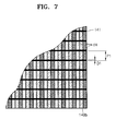
- a black matrix 141 existing between the pixels px of the LCD layer 140b of the LCD panel 140 is used.
- the LCD panel 140 has the black matrix 141 having a width of D1 in the vertical direction that is formed between the pixels px of the LCD layer 140b in order to separate the pixels px from one another.
- the third anisotropic device array 130 as shown in FIG. 8 .
- the opaque mask 131 in a stripe shape corresponding to the black matrix 141 of the LCD panel 140 is horizontally arranged between the seventh and eighth anisotropic devices 130a and 130b of the of the third anisotropic device array 130.
- the width of the opaque mask 131 in the vertical direction is marked as D2.
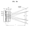
- FIG. 9A illustrates a cross-sectional view of a state in which the opaque mask 131 and the black mask 141 are respectively arranged in the third anisotropic device array 130 and the LCD panel 140, according to an exemplary embodiment of the present invention.
- FIG. 9B is an enlarged view showing the major parts of FIG. 9A that explains the effect of the opaque mask 131 of the third anisotropic device array 130 and the black matrix 141 of the LCD panel 140 for the range of height at which the image of the neighboring viewpoint is accurately separated.
- the width in the vertical direction of the seventh and eighth anisotropic devices 130a and 130b of the third anisotropic device array 130 is P2; the width in the vertical direction of the pixel px of the LCD panel 140 is P1; the range of height at which the image of the neighboring viewpoint is accurately separated is H2; the range of height at which the image of the neighboring viewpoint is separated or reversed is H1; the distance between the third anisotropic device array 130 and the liquid crystal layer 140b of the LCD panel 140 is t; and the viewing distance from the liquid crystal layer 140b of the LCD panel 140 to a viewer is L.
- the width in the vertical direction of the black matrix 141 is D1, and the width in the vertical direction of the opaque mask 131 is D2.
- Equation 2 can be obtained from a trapezoid BGKC and a trapezoid FJKC.
- t L P ⁇ 1 + D ⁇ 1 H ⁇ 2
- Equation 3 can be obtained from the trapezoid BGKC and a trapezoid BGJF.
- t L P ⁇ 2 - D ⁇ 2 P ⁇ 1 + D ⁇ 1
- Equation 5 can be obtained by applying Equation 4 to Equation 2 and expressed with respect to H2.
- the range H2 of height at which the image of the neighboring viewpoint is accurately separated can be greatly increased.
- the width of the opaque mask 131 is increased to its maximum without affecting the brightness of a displayed image.
- the range H2 of height at which the viewpoint is accurately separated can be about 150-200 mm.
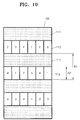
- FIG. 10 illustrates a view showing a viewing zone of an image that is autostereoscopic formed by the multiview autostereoscopic display of FIG. 1 , according to an embodiment of the present invention.
- the image that is autostereoscopic and is accurately separated can be viewed in the range H2 of height.
- An area 111 where the image is not separated and an area 112 where the image is reversed occurs in the range H1 of height.
- the LCD panel 140 does not display the entire image of a frame and then an image of the next frame, but sequentially displays the image of continuous frames from the top to the bottom of a screen.
- the multiview autostereoscopic display according to the present embodiment uses the backlight unit 100 of a division type that is divided into N number of segments 100a. Also, the first and second polarization switches 110 and 125 are separated and switched corresponding to the segments of the backlight unit 100.
- the backlight unit 100 and the first and second polarization switches 110 and 125 are separated into a plurality of horizontal segments that are sequentially switched in synchronism with the vertical scanning time of the LCD panel 140.
- the horizontal segments of the backlight unit 100 and the first and second polarization switches 110 and 125 can be independently switched and are arranged in the vertical direction of the multiview autostereoscopic display.
- the number of segments of the backlight unit 100 and the first and second polarization switches 110 and 125 can be appropriately selected according to the design.
- one of the segments of the backlight unit 100 and the first and second polarization switches 110 and 125 may correspond to a pixel line of the LCD panel 140.
- one of the horizontal segments of each of the backlight unit 100 and the first and second polarization switches 110 and 125 corresponds to a plurality of pixel lines of the LCD panel 140.
- the multiview autostereoscopic display can be manufactured such that one of the segments of the backlight unit 100 and the first and second polarization switches 110 and 125 corresponds to 100 pixel lines of the LCD panel 100.
- the segments of the backlight unit 100 and the first and second polarization switches 110 and 125 which are corresponding to each other can be switched at the same time.
- Each of the horizontal segments of the backlight unit 100 is turned on and off in synchronization with the scanning time of the pixel lines of the LCD panel 140 corresponding thereto.
Landscapes
- Engineering & Computer Science (AREA)
- Multimedia (AREA)
- Signal Processing (AREA)
- Testing, Inspecting, Measuring Of Stereoscopic Televisions And Televisions (AREA)
Description
- The present invention relates to a multiview autostereoscopic display having an extended viewing zone enabling the viewer to see an autostereoscopic image from various positions.
- A binocular parallax method is an effective method for providing an autostereoscopic image in a flat panel display. The binocular parallax method provides a three dimensional image by separating the viewing zones of a left eye and a right eye of a stereopair in order to allow the left and right eyes of a viewer to see different images. A method of separating the left eye image and the right eye image includes a lenticular method, using a lenticular lens array, and a parallax barrier method. According to related art technology, a set of columns, for example, odd columns, are displayed for the left eye image and even columns are displayed for the right eye image, cf.
US-A-2003/107 805 . Since the left eye image and the right eye image area are displayed on the same display panel, however, there is a problem in that the resolution of each image is not more than half the full resolution of the display panel. - As LCD panels having a fast response are recently being developed, the presentation of an autostereoscopic image having the full resolution of an LCD panel may be possible by using a frame that serially displays a left eye image and a right eye image , cf.
US-A-2003/107 805 . In this case, both the left eye image and the right eye image are displayed with the full resolution of the display panel. In this system, in order to provide a sequential display of the frames, a means for displaying the left eye image and the right eye image by selectively switching between the left eye image and the right eye image is required. For example, the resolution of a three dimensional image can be improved using a polarization switch using polarization characteristics.EP-A-0833 183 discloses a design capable of displaying multiple autostereoscopic views. - However, a conventional three dimensional image apparatus has a very narrow viewing zone because the conventional three dimensional image apparatus only provides the image in two viewpoints. Thus, when a viewer moves his head, the left and right images are reversed so that the viewing of a three dimensional image is improper. To solve the problem, an eye-tracking method is used. However, the eye-tracking method has the limitation of only applying to a single viewer.
- Exemplary embodiments of the present invention overcome the above disadvantages and other disadvantages not described above. Also, the present invention is not required to overcome the disadvantages described above, and an exemplary embodiment of the present invention may not overcome any of the problems described above. Exemplary embodiments of the present invention provide a multiview autostereoscopic display that extends a viewing zone of a viewer and enables a viewer to see an autostereoscopic image even when the position of the viewer changes.
- The invention is as defined in appended
claim 1. According to the present invention, there is provided a multiview autostereoscopic display including: a backlight unit; a first polarized panel which transmits light emitted form the backlight unit having a first polarization direction; a first polarization switch which changes the polarization direction of light incident thereon; a first anisotropic device array comprising first, second, third, and fourth anisotropic devices which are sequentially and repeatedly arranged in a horizontal direction, which transmits light such that light transmitted by an anisotropic device has a polarization perpendicular to a polarization of light transmitted by a neighboring anisotropic device; a lenticular lens array comprising a plurality of lenticular lens devices which are arranged in the horizontal direction, the lenticular lens array separating light transmitted form the first, second, third, and fourth anisotropic devices into different directions; a second polarized panel which transmits light emitted form the lenticular lens array having a second polarization direction; a second anisotropic device array, comprising fifth and sixth anisotropic devices, alternately arranged in the horizontal direction, which transmits light such that light transmitted by the fifth anisotropic devices has a polarization perpendicular to a polarization of light emitted from the sixth anisotropic devices; a second polarized switch which changes the polarization direction of light incident thereon; a third anisotropic device array, comprising seventh and eighth anisotropic devices which are alternately arranged in a vertical direction, which transmits light such that light transmitted by the seventh anisotropic devices has a polarization perpendicular to a polarization of light transmitted by the eighth anisotropic devices; and a display panel which forms an image by modulating incident light. - The first through fourth anisotropic devices correspond to one of the lenticular lens devices.
- A pitch of the lenticular lens devices is not greater than a sum of widths in the horizontal direction of the first through fourth anisotropic devices.
- The fifth and sixth anisotropic devices correspond to one of the lenticular lens devices.
- A pitch of the lenticular lens devices is not greater than a sum of widths in the horizontal direction of the fifth and sixth anisotropic devices.
- Each of the seventh and eighth anisotropic devices corresponds to a respective one of a plurality of pixel lines of the display panel.
- An opaque mask having a stripe shape is disposed between the seventh and eighth anisotropic devices.
- A black matrix is arranged between pixels of the display panel. A width of the black matrix in the vertical direction is D1; a width of the opaque mask in the vertical direction is D2; a distance between the pixel of the display panel and the third anisotropic device array is t; a viewing distance from the display panel is L; and a height H2 of a viewing zone where crosstalk does not occur satisfies an equation that H2=(L/t)(D1+D2).
- A width in the vertical direction of each of the seventh and eighth anisotropic devices is not less than a pitch in the vertical direction between pixel lines of the display panel.
- Each of the first and second polarization switches includes a liquid crystal retarder that is electrically controllable, or a polarization rotator.
- A distance between the first anisotropic device array and the lenticular lens array is the same as or greater than a focal length of the lenticular lens device.
- Each of the first through fourth anisotropic devices comprises a polarizer having a predetermined polarization surface, wherein the polarization surfaces of neighboring anisotropic devices are perpendicular to each other.
- Each of the fifth and sixth anisotropic devices comprises a polarizer having a predetermined polarization surface, wherein the polarization surfaces of the polarizers forming the fifth and sixth anisotropic devices are perpendicular to each other.
- Each of the seventh and eighth anisotropic devices comprises a polarizer having a predetermined polarization surface, wherein the polarization surfaces of the polarizers forming the seventh and eighth anisotropic devices are perpendicular to each other.
- The multiview autostereoscopic display according to the exemplary embodiments of the present invention provides a superior autostereoscopic image having no reverse display between the left and right images even when a viewer moves by displaying an image at three or more viewpoints. Thus, the viewer can more freely view the autostereoscopic image. Also, as a multiview image is displayed in an interlacing method using a display panel having a high response speed, an autostereoscopic image of a full resolution is provided. Furthermore, a high quality image is displayed, reducing crosstalk, by arranging an opaque mask of a stripe shape in an anisotropic device array.
-
-
FIG. 1 illustrates a perspective view of a multiview autostereoscopic display according to an exemplary embodiment of the present invention; -
FIG. 2 illustrates a plan view of the multiview autostereoscopic display ofFIG. 1 , according to an exemplary embodiment of the present invention; -
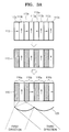
FIG. 3A illustrates a view for explaining the operation of an image formed when a first polarization switch in the multiview autostereoscopic display ofFIG. 1 is off, according to an exemplary embodiment of the present invention; -
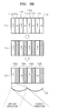
FIG. 3B illustrates a view for explaining the operation of an image formed when the first polarization switch of the multiview autostereoscopic display ofFIG. 1 is on, according to an exemplary embodiment of the present invention; -
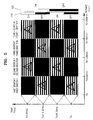
FIG. 4 illustrates a view of an image for each frame of the multiview autostereoscopic display ofFIG. 1 , according to an exemplary embodiment of the present invention; -
FIG. 5 illustrates a view of images at first through fourth viewpoints according to the switching of the first and second polarization switches of the multiview autostereoscopic display ofFIG. 1 , according to an exemplary embodiment of the present invention; -
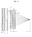
FIG. 6 illustrates a vertical-sectional view of the multiview autostereoscopic display ofFIG. 1 , according to an exemplary embodiment of the present invention; -
FIG. 7 illustrates a partially detailed view of a liquid crystal layer of an LCD panel adopted in the multiview autostereoscopic display ofFIG. 1 , according to an exemplary embodiment of the present invention; -
FIG. 8 illustrates a partially detailed view of a third anisotropic device array adopted in the multiview autostereoscopic display ofFIG. 1 , according to an exemplary embodiment of the present invention; -
FIG. 9A illustrates a view of the structure of the multiview autostereoscopic display ofFIG. 1 in which an opaque mask is formed on the third anisotropic device array, according to an exemplary embodiment of the present invention; -
FIG. 9B illustrates a view for explaining the operational relationship between the LCD panel and the third anisotropic device array ofFIG. 9A ; and -
FIG. 10 illustrates a view of a viewing zone of an image formed by the multiview autostereoscopic display ofFIG. 1 , according to an exemplary embodiment of the present invention. -
FIG. 1 illustrates a perspective view of a multiview autostereoscopic display according to an exemplary embodiment of the present invention. Referring toFIG. 1 , the multiview autostereoscopic display according to the present embodiment includes abacklight unit 100; a firstpolarized panel 105 which only transmits the portion of the light from thebacklight unit 100 which has a particular polarization direction; afirst polarization switch 110 which changes the polarization direction of an incident beam by an electric control; and a firstanisotropic device array 113. - The multiview autostereoscopic display also includes a second
polarized panel 115 which, of the light emitted from the firstanisotropic device array 113, only transmits light having a particular polarization direction; a secondanisotropic device array 120; alenticular lens array 123 which separates the incident beam into viewing zones; asecond polarization switch 125 which changes the polarization direction of the incident beam,; and a thirdanisotropic device array 130. The multiview autostereoscopic display further includes a liquid crystal display (LCD)panel 140 which forms an image by modulating the incident beam in units of pixels.Reference number 150 refers to a viewing plane. - The
backlight unit 100 that supplies light to theLCD panel 140 can include a direct type ofbacklight unit 100 by which the light is illuminated directly towards theLCD panel 140 and can include an edge light type ofbacklight unit 100 by which light is illuminated through a light guide plate from the side of thebacklight unit 100. The type ofbacklight unit 100 may be selected according to the size of theLCD panel 140. The direct type ofbacklight unit 100 is suitable for large-sized display devices while the edge type is suitable for mid- and small-sized display devices. - The first and second
polarized panels polarized panels polarized panel 105 may transmit light having a first polarization direction, for example, horizontally polarized light, and thesecond polarization panel 115 may transmit light having a second polarization direction, for example, vertically polarized light. However, the transmission characteristics of the first and secondpolarized panels LCD panel 140. - The first and second polarization switches 110 and 125 comprise electrically controlled devices that can change the polarization direction of the incident beam according to the amplitude of an applied voltage and can be switched in synchronization with the operation of the
LCD panel 140. For example, a liquid crystal retarder that is electrically controllable or a polarization rotator can be used as a polarization switch. In the present embodiment, a liquid crystal retarder having a switching speed of about 180 Hz is utilized at a relatively low cost. When the first and second polarization switches 110 and 125 are formed of liquid crystal retarders, for example, and the first and second polarization switches 110 and 125 are on, the incident beam is not delayed and when the first and second polarization switches 110 and 125 are off, the incident beam is phase-delayed by 1/2 wavelength (λ/2). - The changed angle of the polarization direction by the first and second polarization switches 110 and 125 is exemplary and can be differently designed according to the polarization directions of the polarizers of the first and second
polarized panels LCD panel 140. -
FIG. 2 illustrates a plan view of the multiview autostereoscopic display ofFIG. 1 , according to an exemplary embodiment of the present invention. Referring toFIG. 2 , the firstanisotropic device array 113, for example, can be arranged on a focal surface of thelenticular lens array 123. First through fourthanisotropic devices FIG. 3a , are sequentially and repeatedly arranged accordingly in the horizontal direction of the multiview autostereoscopic display. The first through fourthanisotropic devices anisotropic device array 113 changes the polarization direction of the incident beam such that the polarization directions of the beams passing through the first through fourthanisotropic devices - For example, each of the first through fourth
anisotropic devices anisotropic devices anisotropic devices anisotropic devices anisotropic devices anisotropic devices anisotropic devices anisotropic devices - The retarders forming the first and third
anisotropic devices anisotropic devices anisotropic devices anisotropic devices anisotropic devices anisotropic devices anisotropic devices anisotropic devices anisotropic devices anisotropic device 113a and the rotator forming the secondanisotropic device 113b are such that a difference in rotational angle of the incident light between the firstanisotropic device 113a and the secondanisotropic device 113b is 90°. For example, the firstanisotropic device 113a does not rotate the incident light while the secondanisotropic device 113b rotates the incident light by 90°, or the firstanisotropic device 113a rotates the incident light by -45° while the secondanisotropic device 113b rotates the incident light by +45°. - According to the present embodiment, the light passing through the first
polarized panel 105, thefirst polarization switch 110, and the firstanisotropic device array 113 may have one of the following polarization statuses according to the on-off switching of thefirst polarization switch 110. First, the light passing through the first and thirdanisotropic devices anisotropic devices anisotropic devices anisotropic devices - Next, the second
anisotropic device array 120 comprises fifth and sixthanisotropic devices FIG. 3A , that are alternately arranged along the horizontal direction of the multiview autostereoscopic display. The fifth and sixthanisotropic devices anisotropic device 120a can be arranged in odd columns of the secondanisotropic device array 120 while the sixthanisotropic device 120b can be arranged in even columns of the secondanisotropic device array 120. The secondanisotropic device array 120 changes the polarization direction of the incident light such that the polarization directions of the light passing through the fifth and sixthanisotropic devices anisotropic device array 120 is formed of polarized panels having polarization surfaces that are perpendicular to each other, retarders having a phase delay difference of λ/2 between the retarders, or rotators having a rotation angle difference of 90° between the rotators. Since the structure and operation of the secondanisotropic device array 120 are substantially the same as those of the firstanisotropic device array 113, a detailed description thereof will be omitted herein. - The
lenticular lens array 123 is formed of a plurality oflenticular lens devices 123a arranged in the horizontal direction of the multiview autostereoscopic display. Each of thelenticular lens devices 123a are longer in the vertical direction of the multiview autostereoscopic display and parallel to the first through fourthanisotropic devices birefringent devices anisotropic devices lenticular lens devices 123a and the fifth and sixthanisotropic devices lenticular lens devices 123a. - The
lenticular lens array 123 emits the incident light by separating the incident light into a plurality of viewpoints. The light passing through thelenticular lens array 123 is separated in different viewing zones of different viewpoints at a viewing distance according to the position where the incident light is incident on thelenticular lens array 123, and forms images. For example, the light output from the firstanisotropic device 113a can proceed in a fourth direction for a fourth viewpoint through thelenticular lens array 123; the light output from the secondanisotropic device 113b can proceed in a third direction for a third viewpoint; the light output from the thirdanisotropic device 113c can proceed in the third direction for the third viewpoint; and the light output from the fourthanisotropic device 113d can proceed in a first direction for a first viewpoint. - As is known in the related art, the interval between the neighboring viewpoints at the viewing distance may be about 65 mm. The pitch between the
lenticular lens devices 123a of thelenticular lens array 123 may be the same as the pitch of a pair of anisotropic device arrays formed of the first through fourthanisotropic devices lenticular lens device 123a may be the same as or slightly less than the sum of the widths of the first through fourthanisotropic devices lenticular lens array 123 and the firstanisotropic device array 113 may be the same as or slightly greater than the focal length of thelenticular lens devices 123a of thelenticular lens array 123. - The
second polarization switch 125 and the thirdanisotropic device array 130 are disposed after thelenticular lens array 123. However, thesecond polarization switch 125 may be disposed before thelenticular lens array 123. - The third
anisotropic device array 130 comprises seventh and eighthanisotropic devices FIG. 1 that are longer in the horizontal direction of the multiview autostereoscopic display and can be alternately arranged along the vertical direction of the multiview autostereoscopic display. The polarization directions of the light passing through the seventh and eighthanisotropic devices anisotropic device array 130 are perpendicular to each other. For example, the seventh and eighthanisotropic devices anisotropic device array 130 comprise polarized panels having polarization surfaces perpendicular to each other, retarders having a phase delay difference of λ/2 between the seventh and eighthanisotropic devices anisotropic devices anisotropic device array 130 are substantially the same as those of the first and secondanisotropic device arrays anisotropic devices anisotropic device arrays - The
LCD panel 140 includes afront polarizer 140a, arear polarizer 140c, and aliquid crystal layer 140b arranged between thefront polarizer 140a and therear polarizer 140c. Thefront polarizer 140a of theLCD panel 140 transmits light polarized in a certain direction and, as the arrangement of the liquid crystal of the liquid crystal layer is changed by an electric control, the transmissivity of the polarized light varies in units of pixels according to the arrangement of the liquid crystal of the liquid crystal layer so as to form an image. - The operation of the multiview autostereoscopic display according to the present embodiment will be described in detail. In the present embodiment, four types of frames can be formed according to the on-off status of the first and second polarization switches 110 and 125. That is, there is a first frame in which the first and second polarization switches 110 and 125 are off; a second frame in which the
first polarization switch 110 is on and thesecond polarization switch 125 is off; a third frame in which thefirst polarization switch 110 is off and thesecond polarization switch 125 is on; and a fourth frame in which the first and second polarization switches 110 and 125 are on. Referring toFIG. 3A , the first frame in which the first and second polarization switches 110 and 125 are off will be described. It is assumed that the firstpolarized panel 105 only transmits horizontally polarized light and the secondpolarized panel 115 only transmits vertically polarized light. InFIGS. 3A and3B , the directions of the arrows indicate the direction of polarization. - The light emitted from the
backlight unit 100 is polarized, for example, into horizontally polarized light by the firstpolarized panel 105 and the polarization direction of the light is changed according to the on-off status of thefirst polarization switch 110. When thefirst polarization switch 110 is off, the horizontally polarized light is changed to vertically polarized light and vertically polarized light is incident on the firstanisotropic device array 113. For example, the light passing through the first and thirdanisotropic devices anisotropic devices polarized panel 115. Thus, in the present embodiment, only the light passing through the second and fourthanisotropic devices anisotropic device array 120. When the vertically polarized light passes through the secondanisotropic device array 120, the light passing through the fifthanisotropic device 120a remains vertically polarized light and the light passing through the sixthanisotropic device 120b is changed to horizontally polarized light. - The vertically polarized light and the horizontally polarized light are separated by the
lenticular lens array 123, such that they are emitted in different directions. The vertically polarized light is directed in the third direction (the third viewpoint) and the horizontally polarized light is directed in the first direction (the first viewpoint). Next, when thesecond polarization switch 125 is off, the polarization direction is changed so that the light is incident on the thirdanisotropic device array 130. Of the vertically polarized light proceeding towards the third direction, the light passing through the seventhanisotropic device 130a is changed to horizontally-polarized light, and the light passing through the eighthanisotropic device 130b remains polarized in the vertical direction. Of the horizontally polarized light proceeding towards the first direction, the light passing through the seventhanisotropic device 130a is changed to vertically polarized light and the light passing through the eighthanisotropic device 130b remains polarized in the horizontal direction. - As a result, the light passing through the third
anisotropic device array 130 includes the horizontally polarized light of the odd lines and the vertically polarized light of the even lines, as light for the third viewpoint, and the vertically polarized light of the odd lines and the horizontally polarized beam of the even lines, as light for the first viewpoint. When thefront polarizer 140a of theLCD panel 140 is assumed to transmit horizontally polarized light, of the light passing through the thirdanisotropic device array 130, only the horizontally polarized light of the odd lines of the light for the third viewpoint passes through thefront polarizer 140a of theLCD panel 140 and only the horizontally polarized light of the even lines of the light for the first viewpoint passes through thefront polarizer 140a of theLCD panel 140. The seventhanisotropic device 130a can be arranged on the odd lines and the eighthanisotropic device 130b can be arranged on the even lines. The seventhanisotropic device 130a of the odd lines may correspond to the pixel of the odd lines of theLCD panel 140 and the eighthanisotropic device 130b of the even lines may correspond to the pixel of the even lines of theLCD panel 140. Thus, an image is displayed by an interlacing method in which an image for the first viewpoint is formed at the pixels of the even lines and an image for the third viewpoint is formed at the pixels of the odd lines. - When the
first polarization switch 110 is off and thesecond polarization switch 125 is on (the third frame), the image for the first viewpoint is formed at the pixels of the odd lines and the image for the third viewpoint is formed at the pixels of the even lines.FIG. 4 illustrates lines for each of the viewpoints for the first through fourth frames, according to an exemplary embodiment of the present invention. - Referring to
FIG. 3B , when thefirst polarization switch 110 is on and thesecond polarization switch 125 is off (the second frame), the light emitted from thebacklight unit 100 is polarized to, for example, horizontally polarized light by the first polarized panel 106. When thefirst polarization switch 110 is on, the horizontally polarized light passes through thefirst polarization switch 110 without a change in the polarization direction and is incident on the firstanisotropic device array 113. The light passing through the first and thirdanisotropic devices anisotropic devices polarized panel 115 transmits only the vertically polarized light. Thus, in the present embodiment, only the light passing through the first and thirdanisotropic devices anisotropic device array 120. When the vertically polarized light passes through the secondanisotropic device array 120, the light passing through the fifthanisotropic device 120a remains vertically polarized and the light passing through the sixthanisotropic device 120b is changed to horizontally polarized light. - The vertically polarized light and the horizontally polarized light are separated by the
lenticular lens array 123 and are emitted in different directions. The vertically polarized light proceeds in the fourth direction (the fourth viewpoint) and the horizontally polarized light proceeds in the first direction (the second viewpoint). Next, when thesecond polarization switch 125 is on, the light is incident on the thirdanisotropic device array 130 without a change in the polarization direction. Of the vertically polarized light proceeding towards the fourth direction, the light passing through the seventhanisotropic device 130a is changed to horizontally-polarized light and the light passing through the eighthanisotropic device 130b remains vertically polarized. Of the horizontally polarized light proceeding towards the second direction, the light passing through the seventhanisotropic device 130a is changed to vertically-polarized light and the light passing through the eighthanisotropic device 130b remains horizontally polarized. - As a result, the light passing through the third
anisotropic device array 130 includes the horizontally polarized light of the odd lines and the vertically polarized light of the even lines, as the light for the fourth viewpoint, and the vertically polarized light of the odd lines and the horizontally polarized light of the even lines, as light for the second viewpoint. Of the light passing through the thirdanisotropic device array 130, only the horizontally polarized light of the odd lines of the beam for the fourth viewpoint passes through thefront polarizer 140a of theLCD panel 140 and only the horizontally polarized light of the even lines of the beam for the second viewpoint passes through thefront polarizer 140a of theLCD panel 140. Thus, an image is displayed by the interlacing method in which an image for the second viewpoint is formed at the pixels of the even lines and an image for the fourth viewpoint is formed at the pixels of the odd lines. By displaying the image through the interlacing method as above, a multiview autostereoscopic image can be provided at a full resolution. - When the
first polarization switch 110 is on and thesecond polarization switch 125 is on (the fourth frame), the image for the second viewpoint is formed at the pixels of the odd lines and the image for the fourth viewpoint is formed at the pixels of the even lines.FIG. 4 illustrates lines where an image is formed for each of the viewpoints at the first through fourth frames, according to an exemplary embodiment of the present invention. -
FIG. 5 illustrates a sequential operation with respect to the first through fourth viewpoints when a refresh rate is, for example, 120 Hz, according to an exemplary embodiment of the present invention. Referring toFIG. 5 , when the first and second polarization switches 110 and 125 are off (the first frame), an image is formed at the first and third viewpoints when t=To. At this time, the image for the first viewpoint is formed at the pixels of the even lines, and the image for the third viewpoint is formed at the pixels of the odd lines. When thefirst polarization switch 110 is on and thesecond polarization switch 125 is off (the second frame), an image is formed at the second and fourth viewpoints when t=To+8.33 (ms). At this time, the image for the second viewpoint is formed at the pixels of the even lines, and the image for the fourth viewpoint is formed at the pixels of the odd lines. When thefirst polarization switch 110 is off and thesecond polarization switch 125 is on (the third frame), an image is formed at the first and third viewpoints when t=To+16.67. At this time, the image for the first viewpoint is formed at the pixels of the odd lines, and the image for the third viewpoint is formed at the pixels of the lines. When thefirst polarization switch 110 is off and thesecond polarization switch 125 is on (the third frame), an image is formed at the first and third viewpoints when t=To+16.67. At this time, the image for the first viewpoint is formed at the pixels of the odd lines, and the image for the third viewpoint is formed at the pixels of the lines. When thefirst polarization switch 110 is on and thesecond polarization switch 125 is on (the fourth frame), an image is formed at the second and fourth viewpoints when t=To+25 (ms). At this time, the image for the second viewpoint is formed at the pixels of the odd lines, and the image for the fourth viewpoint is formed at the pixels of the even lines. - According to the present embodiment, each of the seventh and eighth
anisotropic devices anisotropic device array 130 can correspond to the pixel lines of theLCD panel 140. In the present embodiment, the number of seventh and eighthanisotropic devices anisotropic device array 130 is the same as that of the pixel lines of theLCD panel 140. - Referring to
FIG. 6 , to prevent the occurrence of a Moire pattern on an image displayed on theLCD panel 140, the width P2 in the vertical direction of the seventh and eighthanisotropic devices anisotropic device array 130 is slightly greater than the pitch P1 of the pixel lines of theLCD panel 140.FIG. 6 illustrates a vertical-sectional view of the multiview autostereoscopic display ofFIG. 1 , according to an exemplary embodiment of the present invention. For convenience of explanation, other elements existing between the first and thirdanisotropic device arrays FIG. 6 . - As shown in
FIG. 6 , the seventh and eighthanisotropic devices anisotropic device array 130 are arranged in the vertical direction at the rear of theLCD panel 140 from the perspective of a viewer. Also, a plurality of pixels px are arranged in two dimensions horizontally and vertically on theLCD panel 140. InFIG. 6 , only the pixels px arranged in the vertical direction on theLCD panel 140 can be seen. The eye of a viewer is positioned at a point in front of theLCD panel 140. When an image is focused at a point in the viewing zone, for the beam passing through each of the seventh and eighthanisotropic devices anisotropic device array 130 to pass through the pixel line corresponding thereto, the seventh and eighthanisotropic devices anisotropic device array 130 corresponding to the pixel lines located at a higher or lower position than the eye of the viewer need to be arranged at a higher or lower position than the corresponding pixel lines. To this end, the pitch of the seventh and eighthanisotropic devices anisotropic device array 130 should be slightly greater than the pitch of the pixel lines of theLCD panel 140. For example, when the pitch of the pixel lines of theLCD panel 140 is about 0.265 mm, the pitch of the seventh and eighthanisotropic devices anisotropic device array 130 can be about 0.266 mm. - Crosstalk may occur where the images of neighboring viewpoints are mixed or reversed according to the height of the eye of the viewer. Thus, for the more convenient viewing of an autostereoscopic image, the range of height at which the image at the neighboring viewpoint is accurately separated may be increased. To achieve this purpose, as shown in
FIG. 7 , ablack matrix 141 existing between the pixels px of theLCD layer 140b of theLCD panel 140 is used. In general, theLCD panel 140 has theblack matrix 141 having a width of D1 in the vertical direction that is formed between the pixels px of theLCD layer 140b in order to separate the pixels px from one another. In the thirdanisotropic device array 130 according to the present embodiment, as shown inFIG. 8 . theopaque mask 131 in a stripe shape corresponding to theblack matrix 141 of theLCD panel 140 is horizontally arranged between the seventh and eighthanisotropic devices anisotropic device array 130. The width of theopaque mask 131 in the vertical direction is marked as D2. -
FIG. 9A illustrates a cross-sectional view of a state in which theopaque mask 131 and theblack mask 141 are respectively arranged in the thirdanisotropic device array 130 and theLCD panel 140, according to an exemplary embodiment of the present invention.FIG. 9B is an enlarged view showing the major parts ofFIG. 9A that explains the effect of theopaque mask 131 of the thirdanisotropic device array 130 and theblack matrix 141 of theLCD panel 140 for the range of height at which the image of the neighboring viewpoint is accurately separated. The width in the vertical direction of the seventh and eighthanisotropic devices anisotropic device array 130 is P2; the width in the vertical direction of the pixel px of theLCD panel 140 is P1; the range of height at which the image of the neighboring viewpoint is accurately separated is H2; the range of height at which the image of the neighboring viewpoint is separated or reversed is H1; the distance between the thirdanisotropic device array 130 and theliquid crystal layer 140b of theLCD panel 140 is t; and the viewing distance from theliquid crystal layer 140b of theLCD panel 140 to a viewer is L. The width in the vertical direction of theblack matrix 141 is D1, and the width in the vertical direction of theopaque mask 131 is D2. InFIG. 9B ,Equation 1 can be obtained from a triangle ABC and a triangle EFC as follows.
[Math.1]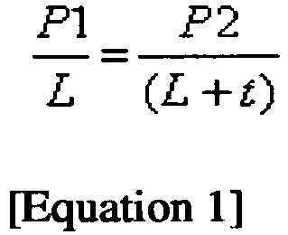
-
Equation 2 can be obtained from a trapezoid BGKC and a trapezoid FJKC.
[Math.2]
-
Equation 3 can be obtained from the trapezoid BGKC and a trapezoid BGJF.
[Math.3]
- P1 can be expressed as follows from
Equations
[Math.4]
- Equation 5 can be obtained by applying
Equation 4 toEquation 2 and expressed with respect to H2.
[Math.5]
- Here, since t « L, the term (t/L)D1 can be ignored. Thus, Equation 6 can be obtained as follows.
[Math.6]
- Referring to Equation 6, as the widths D1 and D2 of the
black matrix 141 of theLCD panel 140 and theopaque mask 131 of the thirdanisotropic device array 130 increase, the range H2 of height at which the image of the neighboring viewpoint is accurately separated can be greatly increased. Thus, according to the present embodiment, in order to increase the range H2 of height at which the viewpoint is accurately separated, the width of theopaque mask 131 is increased to its maximum without affecting the brightness of a displayed image. By doing so, the range H2 of height at which the viewpoint is accurately separated can be about 150-200 mm. -
FIG. 10 illustrates a view showing a viewing zone of an image that is autostereoscopic formed by the multiview autostereoscopic display ofFIG. 1 , according to an embodiment of the present invention. The image that is autostereoscopic and is accurately separated can be viewed in the range H2 of height. Anarea 111 where the image is not separated and anarea 112 where the image is reversed occurs in the range H1 of height. - In the meantime, the
LCD panel 140 does not display the entire image of a frame and then an image of the next frame, but sequentially displays the image of continuous frames from the top to the bottom of a screen. Thus, while the images of the two frames displayed on a screen, crosstalk may occur that images of different viewpoints are mixed and displayed. To solve this problem, the multiview autostereoscopic display according to the present embodiment, as shown inFIG. 1 , uses thebacklight unit 100 of a division type that is divided into N number ofsegments 100a. Also, the first and second polarization switches 110 and 125 are separated and switched corresponding to the segments of thebacklight unit 100. That is, thebacklight unit 100 and the first and second polarization switches 110 and 125 are separated into a plurality of horizontal segments that are sequentially switched in synchronism with the vertical scanning time of theLCD panel 140. The horizontal segments of thebacklight unit 100 and the first and second polarization switches 110 and 125 can be independently switched and are arranged in the vertical direction of the multiview autostereoscopic display. - According to the present embodiment, the number of segments of the
backlight unit 100 and the first and second polarization switches 110 and 125 can be appropriately selected according to the design. To completely remove crosstalk, one of the segments of thebacklight unit 100 and the first and second polarization switches 110 and 125 may correspond to a pixel line of theLCD panel 140. However, in the present embodiment, since the manufacturing costs are largely increased, one of the horizontal segments of each of thebacklight unit 100 and the first and second polarization switches 110 and 125 corresponds to a plurality of pixel lines of theLCD panel 140. For example, the multiview autostereoscopic display can be manufactured such that one of the segments of thebacklight unit 100 and the first and second polarization switches 110 and 125 corresponds to 100 pixel lines of theLCD panel 100. - In this structure, the segments of the
backlight unit 100 and the first and second polarization switches 110 and 125 which are corresponding to each other can be switched at the same time. Each of the horizontal segments of thebacklight unit 100 is turned on and off in synchronization with the scanning time of the pixel lines of theLCD panel 140 corresponding thereto. Thus, when different frames are simultaneously displayed on the same screen, since these frames are displayed by the beams having different polarization directions, crosstalk can be prevented.
Claims (15)
- A multiview autostereoscopic display comprising:a backlight unit (100);a first polarization panel (105) arranged to transmit light emitted from the backlight unit having a first polarization direction;a first polarization switch (110) arranged to change the polarization direction of light from the first polarization panel (105) incident thereon;a first anisotropic device array (113) comprising first, second, third, and fourth anisotropic devices (113a, 113b, 113c, 113d) which are sequentially and repeatedly arranged in a horizontal direction, arranged to receive light from the first polarization switch (110) and to transmit light such that light transmitted by an anisotropic device has a second polarization direction perpendicular to a third polarization direction of light transmitted by a neighboring anisotropic device;a second polarization panel (115) arranged to transmit light transmitted from the first anisotropic device array (113) having said second polarization direction;a second anisotropic device array (120) arranged after the second polarization panel (115), comprising fifth and sixth anisotropic devices (120a, 120b) alternately arranged in the horizontal direction, arranged to transmit light such that light transmitted by the fifth anisotropic devices (120a) has a polarization perpendicular to a polarization of light transmitted by the sixth anisotropic devices (120b);a lenticular lens array (123) comprising a plurality of lenticular lens devices (123a) which are arranged in the horizontal direction, the lenticular lens array (123) separating into different directions light transmitted from the first, second, third, and fourth anisotropic devices having been transmitted through the fifth or sixth anisotropic devices (120a, 120b);a second polarization switch (125) arranged after the second anisotropic device array (120), the second polarization switch (125) being arranged to change the polarization direction of light incident thereon;a third anisotropic device array (130) arranged after the second polarization switch (125), comprising seventh and eighth anisotropic devices (130a, 130b) which are alternately arranged in a vertical direction, arranged to transmit light such that light transmitted by the seventh anisotropic devices (130a) has a polarization perpendicular to a polarization of light transmitted by the eighth anisotropic devices (130b); anda display panel arranged to form an image by modulating incident light.
- The multiview autostereoscopic display of claim 1, wherein the first, second, third, and fourth anisotropic devices (113a, 113b, 113c, 113d) correspond to one of the lenticular lens devices (123a).
- The multiview autostereoscopic display of claim 2, wherein a pitch of the lenticular lens devices (123a) is not greater than a sum of widths in the horizontal direction of the first, second, third, and fourth anisotropic devices (113a, 113b, 113c, 113d).
- The multiview autostereoscopic display of claim 1, wherein the fifth and sixth anisotropic devices (120a, 120b) correspond to one of the lenticular lens devices (123a).
- The multiview autostereoscopic display of claim 4, wherein a pitch of the lenticular lens devices (123a) is not greater than a sum of widths in the horizontal direction of the fifth and sixth anisotropic devices (120a, 120b).
- The multiview autostereoscopic display of claim 1, wherein each of the seventh and eighth anisotropic devices (130a, 130b) corresponds to a respective one of a plurality of pixel lines of the display panel.
- The multiview autostereoscopic display of claim 6, further comprising an opaque mask having a stripe shape disposed between the seventh and eighth anisotropic devices (130a, 130b).
- The multiview autostereoscopic display of claim 7, further comprising a black matrix disposed between pixels of the display panel,
wherein a width of the black matrix in the vertical direction is D1, a width of the opaque mask in the vertical direction is D2, a distance between a pixel of the display panel and the third anisotropic device array is t, a viewing distance from the display panel is L, and a height H2 of a viewing zone where crosstalk does not occur satisfies an equation that: H2=(L/t)(D1+D2). - The multiview autostereoscopic display of claim 6, wherein a width in the vertical direction of each of the seventh and eighth anisotropic devices (130a, 130b) is not less than a pitch in the vertical direction between pixel lines of the display panel.
- The multiview autostereoscopic display of claim 1, wherein a distance between the first anisotropic device array (113) and the lenticular lens array (123) is not less than a focal length of the lenticular lens device (123a).
- The multiview autostereoscopic display of claim 1, wherein each of the first through fourth anisotropic devices (113a, 113b, 113c, 113d) comprises a polarizer having a predetermined polarization surface, wherein the polarization surfaces of neighboring anisotropic devices are perpendicular to each other.
- The multiview autostereoscopic display of claim 1, wherein each of the fifth and sixth anisotropic devices (120a, 120b) comprises a polarizer having a predetermined polarization surface, wherein the polarization surfaces of the polarizers forming the fifth and sixth anisotropic devices (120a, 120b) are perpendicular to each other.
- The multiview autostereoscopic display of claim 1, wherein each of the seventh and eighth anisotropic devices (130a, 130b) comprises a polarizer having a predetermined polarization surface, wherein the polarization surfaces of the polarizers forming the seventh and eighth anisotropic devices (130a, 130b) are perpendicular to each other.
- The multiview autostereoscopic display of claim 1, wherein each of the first through fourth anisotropic devices (113a, 113b, 113c, 113d) comprises a retarder that delays the incident beam by a predetermined phase, wherein a phase delay difference between neighboring anisotropic devices is λ/2.
- The multiview autostereoscopic display of claim 1, wherein each of the fifth and sixth anisotropic devices (120a, 120b) comprises a retarder that delays the incident beam by a predetermined phase, wherein a phase delay difference between the retarders forming the fifth and sixth anisotropic devices is λ/2.
Applications Claiming Priority (3)
| Application Number | Priority Date | Filing Date | Title |
|---|---|---|---|
| US79737206P | 2006-05-04 | 2006-05-04 | |
| KR1020060067302A KR101255210B1 (en) | 2006-05-04 | 2006-07-19 | Multiview autostereoscopic display |
| PCT/KR2007/002007 WO2007129819A1 (en) | 2006-05-04 | 2007-04-25 | Multiview autostereoscopic display |
Publications (3)
| Publication Number | Publication Date |
|---|---|
| EP2014103A1 EP2014103A1 (en) | 2009-01-14 |
| EP2014103A4 EP2014103A4 (en) | 2013-05-15 |
| EP2014103B1 true EP2014103B1 (en) | 2015-12-09 |
Family
ID=39063151
Family Applications (1)
| Application Number | Title | Priority Date | Filing Date |
|---|---|---|---|
| EP07746168.9A Ceased EP2014103B1 (en) | 2006-05-04 | 2007-04-25 | Multiview autostereoscopic display |
Country Status (5)
| Country | Link |
|---|---|
| US (1) | US7626644B2 (en) |
| EP (1) | EP2014103B1 (en) |
| KR (1) | KR101255210B1 (en) |
| CN (1) | CN101438599B (en) |
| WO (1) | WO2007129819A1 (en) |
Families Citing this family (42)
| Publication number | Priority date | Publication date | Assignee | Title |
|---|---|---|---|---|
| KR100813977B1 (en) * | 2005-07-08 | 2008-03-14 | 삼성전자주식회사 | High resolution 2D-3D switchable autostereoscopic display apparatus |
| KR100782831B1 (en) * | 2006-01-03 | 2007-12-06 | 삼성전자주식회사 | Field sequential autostereoscopic display arrangement with high resolution |
| JP5243439B2 (en) * | 2006-10-06 | 2013-07-24 | スリーエム イノベイティブ プロパティズ カンパニー | Backlight module for autostereoscopic 3D display device and scanning backlight for LCD device |
| CN101843105B (en) * | 2007-11-02 | 2013-06-12 | 皇家飞利浦电子股份有限公司 | Autostereoscopic display device |
| JP4404146B2 (en) * | 2008-01-17 | 2010-01-27 | パナソニック株式会社 | Projection type 3D image reproduction device |
| CN101946521B (en) * | 2008-02-11 | 2013-01-23 | 皇家飞利浦电子股份有限公司 | Autostereoscopic image output device |
| PL2286298T3 (en) * | 2008-06-02 | 2017-05-31 | Koninklijke Philips N.V. | An optical arrangement and an autostereoscopic display device incorporating the same |
| US20110080639A1 (en) * | 2009-08-05 | 2011-04-07 | Bradley Nelson | Method and apparatus for displaying 3-dimensional images incorporating angular correction |
| KR101279122B1 (en) * | 2009-11-24 | 2013-06-26 | 엘지디스플레이 주식회사 | Image display device |
| US9247286B2 (en) * | 2009-12-31 | 2016-01-26 | Broadcom Corporation | Frame formatting supporting mixed two and three dimensional video data communication |
| US8854531B2 (en) * | 2009-12-31 | 2014-10-07 | Broadcom Corporation | Multiple remote controllers that each simultaneously controls a different visual presentation of a 2D/3D display |
| US8964013B2 (en) * | 2009-12-31 | 2015-02-24 | Broadcom Corporation | Display with elastic light manipulator |
| US8823782B2 (en) | 2009-12-31 | 2014-09-02 | Broadcom Corporation | Remote control with integrated position, viewer identification and optical and audio test |
| KR101652405B1 (en) * | 2010-06-23 | 2016-08-30 | 삼성전자주식회사 | Three dimensional image display apparatus |
| KR101697181B1 (en) * | 2010-09-07 | 2017-01-17 | 삼성전자주식회사 | Image processing apparatus and method using eye tracking of user |
| US20130314515A1 (en) * | 2010-10-22 | 2013-11-28 | Samsung Electronics Co., Ltd. | Stereoscopic display system, glasses used for the system, and display method therefor |
| CN102056001B (en) * | 2010-11-08 | 2012-08-15 | 友达光电股份有限公司 | Stereoscopic display with multiple viewing angles |
| WO2012156816A1 (en) * | 2011-05-17 | 2012-11-22 | Setred As | Autostereoscopic display system |
| CN102314016A (en) * | 2011-08-10 | 2012-01-11 | 南京中电熊猫液晶显示科技有限公司 | Liquid crystal display panel capable of enhancing three-dimensional (3D) display effect and manufacturing method thereof |
| JP6030578B2 (en) * | 2011-12-28 | 2016-11-24 | パナソニック インテレクチュアル プロパティ コーポレーション オブ アメリカPanasonic Intellectual Property Corporation of America | Light source control device and video display device |
| TWI447436B (en) | 2012-01-11 | 2014-08-01 | Delta Electronics Inc | Multi-view autostereoscopic display |
| KR101323465B1 (en) * | 2012-05-22 | 2013-10-29 | 엘지디스플레이 주식회사 | A patterned retarder type display device having black strips |
| KR102191552B1 (en) | 2012-06-01 | 2020-12-16 | 코닌클리케 필립스 엔.브이. | Autostereoscopic display device and driving method |
| KR101370416B1 (en) * | 2012-07-02 | 2014-03-06 | 엘지디스플레이 주식회사 | Liquid Crystal Display Device and Method for Manufacturing The Same |
| JP5696107B2 (en) * | 2012-09-11 | 2015-04-08 | 株式会社東芝 | Image processing apparatus, method, program, and stereoscopic image display apparatus |
| KR101335526B1 (en) | 2012-09-12 | 2013-12-02 | 엘지디스플레이 주식회사 | Stereoscopic image display |
| CN103780893B (en) * | 2012-10-19 | 2015-09-02 | 瀚宇彩晶股份有限公司 | Stereoscopic display module and electronic device capable of displaying stereoscopic images |
| CN103841395B (en) * | 2012-11-27 | 2016-10-05 | 联想(北京)有限公司 | Composograph display packing and equipment |
| US9265458B2 (en) | 2012-12-04 | 2016-02-23 | Sync-Think, Inc. | Application of smooth pursuit cognitive testing paradigms to clinical drug development |
| US9380976B2 (en) | 2013-03-11 | 2016-07-05 | Sync-Think, Inc. | Optical neuroinformatics |
| US9552777B2 (en) * | 2013-05-10 | 2017-01-24 | Microsoft Technology Licensing, Llc | Phase control backlight |
| KR102208960B1 (en) | 2014-04-09 | 2021-01-28 | 삼성전자주식회사 | Holographic display |
| US10088689B2 (en) | 2015-03-13 | 2018-10-02 | Microsoft Technology Licensing, Llc | Light engine with lenticular microlenslet arrays |
| WO2017041072A1 (en) * | 2015-09-05 | 2017-03-09 | Leia Inc. | Multibeam diffraction grating-based display with head tracking |
| US10798371B2 (en) | 2015-09-05 | 2020-10-06 | Leia Inc. | Multiview display with head tracking |
| PT3563082T (en) | 2016-12-28 | 2021-08-10 | Leia Inc | Multiview backlighting employing fluorescent multibeam elements |
| KR102353696B1 (en) | 2016-12-28 | 2022-01-20 | 레이아 인코포레이티드 | Multi-view display with reflective support structure |
| KR102370247B1 (en) | 2017-06-16 | 2022-03-04 | 레이아 인코포레이티드 | How to use multi-view backlights, multi-view displays and offset multi-beam devices |
| CA3107775A1 (en) | 2018-08-26 | 2020-03-05 | Leia Inc. | Multiview display, system, and method with user tracking |
| NL2022312B1 (en) * | 2018-12-24 | 2020-07-21 | Zhangjiagang Kangde Xin Optronics Mat Co Ltd | Switchable autostereoscopic display with a capacitive touch location sensor |
| WO2022245040A1 (en) * | 2021-05-20 | 2022-11-24 | 삼성전자 주식회사 | Method and device for controlling luminance |
| CN114326129B (en) * | 2022-02-22 | 2024-11-15 | 亿信科技发展有限公司 | A virtual reality glasses |
Family Cites Families (19)
| Publication number | Priority date | Publication date | Assignee | Title |
|---|---|---|---|---|
| US5917562A (en) * | 1994-12-16 | 1999-06-29 | Sharp Kabushiki Kaisha | Autostereoscopic display and spatial light modulator |
| GB2317710A (en) * | 1996-09-27 | 1998-04-01 | Sharp Kk | Spatial light modulator and directional display |
| US6108064A (en) * | 1997-11-06 | 2000-08-22 | Sharp Kabushiki Kaisha | Reflective-type liquid crystal display device including a single polarizer plate |
| GB2337388A (en) * | 1998-05-12 | 1999-11-17 | Sharp Kk | Directional autereoscopic 3D display having directional illumination system |
| GB0017008D0 (en) * | 2000-07-12 | 2000-08-30 | Street Graham S B | Structured light source |
| GB0119176D0 (en) * | 2001-08-06 | 2001-09-26 | Ocuity Ltd | Optical switching apparatus |
| US7557876B2 (en) * | 2003-07-25 | 2009-07-07 | Nitto Denko Corporation | Anisotropic fluorescent thin crystal film and backlight system and liquid crystal display incorporating the same |
| GB2405519A (en) * | 2003-08-30 | 2005-03-02 | Sharp Kk | A multiple-view directional display |
| JP4027898B2 (en) * | 2004-01-29 | 2007-12-26 | 株式会社有沢製作所 | Polarized transmission screen and stereoscopic image display apparatus using the polarized transmission screen |
| JP2005215325A (en) * | 2004-01-29 | 2005-08-11 | Arisawa Mfg Co Ltd | Stereoscopic image display device |
| KR20050098629A (en) * | 2004-04-08 | 2005-10-12 | 삼성전자주식회사 | Liquid crystal display |
| JP4934975B2 (en) * | 2005-03-17 | 2012-05-23 | エプソンイメージングデバイス株式会社 | Image display device |
| JP4591150B2 (en) * | 2005-03-30 | 2010-12-01 | エプソンイメージングデバイス株式会社 | Liquid crystal display |
| KR100813977B1 (en) * | 2005-07-08 | 2008-03-14 | 삼성전자주식회사 | High resolution 2D-3D switchable autostereoscopic display apparatus |
| KR101128519B1 (en) * | 2005-08-04 | 2012-03-27 | 삼성전자주식회사 | High resolution autostereoscopic display |
| KR100782831B1 (en) * | 2006-01-03 | 2007-12-06 | 삼성전자주식회사 | Field sequential autostereoscopic display arrangement with high resolution |
| JP4650279B2 (en) * | 2006-01-19 | 2011-03-16 | エプソンイメージングデバイス株式会社 | Electro-optical device and electronic apparatus |
| JP2007212959A (en) | 2006-02-13 | 2007-08-23 | Nippon Oil Corp | Transmission type liquid crystal display device |
| KR101255209B1 (en) * | 2006-05-04 | 2013-04-23 | 삼성전자주식회사 | Hihg resolution autostereoscopic display apparatus with lnterlaced image |
-
2006
- 2006-07-19 KR KR1020060067302A patent/KR101255210B1/en not_active Expired - Fee Related
-
2007
- 2007-04-17 US US11/785,348 patent/US7626644B2/en not_active Expired - Fee Related
- 2007-04-25 EP EP07746168.9A patent/EP2014103B1/en not_active Ceased
- 2007-04-25 WO PCT/KR2007/002007 patent/WO2007129819A1/en not_active Ceased
- 2007-04-25 CN CN2007800159834A patent/CN101438599B/en not_active Expired - Fee Related
Also Published As
| Publication number | Publication date |
|---|---|
| US20070258140A1 (en) | 2007-11-08 |
| CN101438599A (en) | 2009-05-20 |
| WO2007129819A1 (en) | 2007-11-15 |
| EP2014103A1 (en) | 2009-01-14 |
| US7626644B2 (en) | 2009-12-01 |
| CN101438599B (en) | 2011-12-14 |
| KR101255210B1 (en) | 2013-04-23 |
| KR20070108046A (en) | 2007-11-08 |
| EP2014103A4 (en) | 2013-05-15 |
Similar Documents
| Publication | Publication Date | Title |
|---|---|---|
| US7626644B2 (en) | Multiview autostereoscopic display | |
| US8284241B2 (en) | High resolution autostereoscopic display apparatus with interlaced image | |
| EP2062444B1 (en) | Multi-view autostereoscopic display with improved resolution | |
| CN100430778C (en) | High resolution 2D-3D switchable autostereoscopic display device | |
| JP4925702B2 (en) | Stereoscopic video display device for 2D / 3D video compatibility using a polarizing grating screen | |
| US7830579B2 (en) | Stereoscopic-image display apparatus | |
| EP1666950B1 (en) | Parallax barrier for an autostereoscopic display | |
| EP2055110B1 (en) | Display device | |
| EP1950980B1 (en) | Autostereoscopic 2D/3D switchable display apparatus with high light efficiency, employing a lenticular screen and time-multiplexing of 3D-views | |
| US7646537B2 (en) | High-resolution field sequential autostereoscopic display | |
| EP1750459B1 (en) | High-resolution autostereoscopic display | |
| KR101555892B1 (en) | Auto-stereoscopic display device | |
| KR101086411B1 (en) | Stereoscopic image display device for 2D / 3D image compatibility | |
| CN101356832B (en) | High resolution autostereoscopic display apparatus with interlaced image | |
| KR20120052236A (en) | Multi-view autostereoscopic display device | |
| JP2003202517A (en) | 3D image display device | |
| KR20150004028A (en) | 3 dimensional stereography image displayable device |
Legal Events
| Date | Code | Title | Description |
|---|---|---|---|
| PUAI | Public reference made under article 153(3) epc to a published international application that has entered the european phase |
Free format text: ORIGINAL CODE: 0009012 |
|
| 17P | Request for examination filed |
Effective date: 20081104 |
|
| AK | Designated contracting states |
Kind code of ref document: A1 Designated state(s): AT BE BG CH CY CZ DE DK EE ES FI FR GB GR HU IE IS IT LI LT LU LV MC MT NL PL PT RO SE SI SK TR |
|
| AX | Request for extension of the european patent |
Extension state: AL BA HR MK RS |
|
| DAX | Request for extension of the european patent (deleted) | ||
| RBV | Designated contracting states (corrected) |
Designated state(s): IT NL |
|
| REG | Reference to a national code |
Ref country code: DE Ref legal event code: 8566 |
|
| RAP1 | Party data changed (applicant data changed or rights of an application transferred) |
Owner name: SAMSUNG ELECTRONICS CO., LTD. |
|
| A4 | Supplementary search report drawn up and despatched |
Effective date: 20130416 |
|
| RIC1 | Information provided on ipc code assigned before grant |
Ipc: H04N 13/04 20060101ALI20130410BHEP Ipc: H04N 13/00 20060101AFI20130410BHEP |
|
| 17Q | First examination report despatched |
Effective date: 20130429 |
|
| GRAP | Despatch of communication of intention to grant a patent |
Free format text: ORIGINAL CODE: EPIDOSNIGR1 |
|
| INTG | Intention to grant announced |
Effective date: 20150611 |
|
| GRAS | Grant fee paid |
Free format text: ORIGINAL CODE: EPIDOSNIGR3 |
|
| GRAA | (expected) grant |
Free format text: ORIGINAL CODE: 0009210 |
|
| AK | Designated contracting states |
Kind code of ref document: B1 Designated state(s): IT NL |
|
| REG | Reference to a national code |
Ref country code: NL Ref legal event code: FP |
|
| PG25 | Lapsed in a contracting state [announced via postgrant information from national office to epo] |
Ref country code: IT Free format text: LAPSE BECAUSE OF FAILURE TO SUBMIT A TRANSLATION OF THE DESCRIPTION OR TO PAY THE FEE WITHIN THE PRESCRIBED TIME-LIMIT Effective date: 20151209 |
|
| PLBE | No opposition filed within time limit |
Free format text: ORIGINAL CODE: 0009261 |
|
| STAA | Information on the status of an ep patent application or granted ep patent |
Free format text: STATUS: NO OPPOSITION FILED WITHIN TIME LIMIT |
|
| 26N | No opposition filed |
Effective date: 20160912 |
|
| PGFP | Annual fee paid to national office [announced via postgrant information from national office to epo] |
Ref country code: NL Payment date: 20190321 Year of fee payment: 13 |
|
| REG | Reference to a national code |
Ref country code: NL Ref legal event code: MM Effective date: 20200501 |
|
| PG25 | Lapsed in a contracting state [announced via postgrant information from national office to epo] |
Ref country code: NL Free format text: LAPSE BECAUSE OF NON-PAYMENT OF DUE FEES Effective date: 20200501 |