EP2014147B1 - Verteilungsgerät mit einem verbesserten Behälter - Google Patents
Verteilungsgerät mit einem verbesserten Behälter Download PDFInfo
- Publication number
- EP2014147B1 EP2014147B1 EP08104658A EP08104658A EP2014147B1 EP 2014147 B1 EP2014147 B1 EP 2014147B1 EP 08104658 A EP08104658 A EP 08104658A EP 08104658 A EP08104658 A EP 08104658A EP 2014147 B1 EP2014147 B1 EP 2014147B1
- Authority
- EP
- European Patent Office
- Prior art keywords
- storage tank
- cover
- lid
- articulation
- upper edge
- Prior art date
- Legal status (The legal status is an assumption and is not a legal conclusion. Google has not performed a legal analysis and makes no representation as to the accuracy of the status listed.)
- Active
Links
Images


Classifications
-
- A—HUMAN NECESSITIES
- A01—AGRICULTURE; FORESTRY; ANIMAL HUSBANDRY; HUNTING; TRAPPING; FISHING
- A01C—PLANTING; SOWING; FERTILISING
- A01C15/00—Fertiliser distributors
- A01C15/005—Undercarriages, tanks, hoppers, stirrers specially adapted for seeders or fertiliser distributors
- A01C15/006—Hoppers
Definitions
- the present invention relates to a dispensing apparatus comprising a storage tank with an upper portion and a cover for covering said upper portion, said upper portion having an upper edge. It relates to the general technical field of agricultural machinery and more particularly for devices for dispensing seed or material in granules and / or powder.
- This known seed drill comprises a hopper having an upper portion having a large opening for seed supply.
- the upper part has an upper edge.
- a large lid is provided to cover this opening.
- the lid is retracted by tilting towards the front of the seeder, taking into account the direction of advance.
- the cover is articulated on the edge opposite the upper edge by means of articulations arranged substantially horizontally and perpendicular to the direction of advance.
- the cover In the open position, the cover is therefore in a substantially vertical position at the front of the hopper. A supply from the front, considering the direction in advance, is not possible.
- the vertical position of the lid and the large distance between the wall comprising the upper edge and the wall with the opposite edge of the hopper makes closing the lid particularly difficult. Because of the large size of the lid, the area exposed to the wind is important. This is why closing the cover by tilting from the vertical position to the horizontal position is difficult.
- the cover and the joints must be dimensioned accordingly.
- the document DE91 11 816U describes a hopper for a seeder.
- the opening in the upper part of the hopper is covered by a cover.
- the lid is hinged on each side on the upper part by means of a respective rod. The position and orientation of the joints cause painful handling as the lid opens towards the user. Moreover with only one pair of connecting rods, the lid is not stable.
- the document US 4,502,610 refers to a lid for a hopper, the upper part of the hopper is covered by a lid made in two parts.
- the hopper has means for disengaging the half-lids in a plane parallel to the upper edge of the hopper. These means allow a sliding of a half-cover relative to the other to move closer or further in a longitudinal direction.
- each half-cover comprises two guide rails intended to receive rollers mounted free to rotate on the opposite walls of the hopper.
- These means must be completed by stops limiting the sliding of the half-covers in both directions.
- This solution requires the use of a large number of parts. Such a solution entails a further technical difficulty with respect to the seal.
- the joint plane between the two half-covers must be waterproof and dust-proof, which makes this solution expensive.
- the present invention aims to provide a dispensing apparatus with a storage tank to overcome the disadvantages of the state of the art and in particular by providing a storage tank with a cover that is easy to handle and whose exposed surface the wind is reduced.
- an important feature of the invention consists in that said means consist of at least one pair of links articulated between said storage tank and said cover and that said connecting rods are arranged to form substantially a deformable quadrilateral .
- the manipulation of the lid is relatively simple and practical.
- the surface of the lid exposed to the wind is greatly reduced.
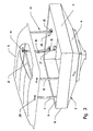
- the dispensing apparatus (1) shown on the figure 1 comprises a storage tank (2) with an upper part (3) with a substantially rectangular outline and a lower part (4) in the approximate shape of an inverted pyramid.
- the upper portion (3) substantially rectangular contour serves as an opening for supplying the storage tank (2).
- the upper portion (3) has an upper edge (6).
- the walls of the storage tank (2) converge towards the lower part (4).
- the storage tank (2) is equipped with a riser (9).
- the extension (9) increases the capacity of the storage tank (2).
- its upper part (3) is protected by a cover (5).
- the lid (5) rests at least substantially on the upper edge (6) of the upper part (3) when closed.
- This apparatus (1) can dispense seeds or materials in the form of granules and / or powder.
- the dispensing apparatus (1) comprises in a known manner elements (7) for dispensing seeds or other substances.
- a dosing member (8) which provides the amount of seeds or other substances for all the elements (7).
- the elements (7) are for example coulters, nozzles ...
- the dispensing apparatus (1) of the figure 1 is a planter for planting seeds or seed in the soil.
- the storage tank (2) is commonly called hopper and the elements (7) are seed coulters.
- the Figures 2 to 4 represent the storage tank (2) with the cover (5) of the invention in different positions.
- the figure 2 illustrates the storage tank (2) during work or for winter storage, the lid (5) is closed.
- the cover (5) is in an intermediate position.
- the figure 4 illustrates the lid in an open or unobstructed position. This position allows the supply of the storage tank (2) during the sowing. It is necessary to clear the upper part (3) to fill the storage tank with seeds.
- the intermediate position is a position of the cover (5) between the open position and the closed position and vice versa.
- the lid (5) is movable between a closed working position and an open filling position.
- the storage tank (2) has means (10) for disengaging the lid (5) in a plane substantially parallel to the plane containing the upper edge (6) of the upper part (3). ).
- the clearance in a substantially horizontal plane considerably reduces the surface of the cover (5) exposed to the wind. The handling of this lid (5) is thus rather simple and practical.
- the means (10) allowing the cover (5) to disengage are at least one pair of connecting rods (11, 12).
- the connecting rods (11, 12) are connected on the one hand to the storage tank (2) and on the other hand to the lid (5). They are arranged to substantially form a deformable quadrilateral. This deformable quadrilateral is preferably a parallelogram.
- the first connecting rod (11) is connected to the storage tank (2) by means of a first articulation (13) and is connected to the cover (5) by means of a second articulation (14).
- the second connecting rod (12) is connected to the storage tank (2) by means of a third articulation (15) and is connected to the cover (5) by means of a fourth articulation (16).
- the joints (13, 15) are arranged substantially on the same substantially horizontal line. This line is substantially parallel to the upper edge (6) of the storage tank (2).
- the length of the first connecting rod (11) is equal to the length of the second connecting rod (12) and the second connecting rod (12) is substantially parallel to the first connecting rod (11).
- these rods (11, 12) advantageously form a parallelogram. Thanks to the kinematics of a parallelogram, the cover (5) maintains a position substantially parallel to the plane containing the upper edge (6) irrespective of its position relative to the storage tank (2). The surface of the cover (5) exposed to the wind is reduced. The lid (5) is moved in a combined rotational and translational movement with respect to the first hinge (13) and the third hinge (15).
- Big bags are large bags containing about 500 kg of seeds or substances.
- the opening of the lid (5) at the level of the upper part (3) must be sufficiently big.
- the cover (5) is released by more than half of the upper part (3).
- the seeds form a dome approximately in the center of the storage tank (2).
- the dome usually extends above the upper edge (6) of the storage tank (2).
- the cover (5) Due to the position on the same horizontal line of the joints (13, 15) and connecting rods (11, 12) forming a parallelogram, the cover (5) will cover the opening of the storage tank (2) without interfering with the dome during of its closure. Thanks to the rods (11, 12), the lid (5) is lifted from a height relative to the upper part (3) of the storage tank (2) during closing as when opening. This raised position is illustrated by the figure 3 . It is noted that the cover (5) disengages in height and laterally while remaining in a plane substantially parallel to the upper edge (6) when it is released ( figure 4 ).
- the conformation of the connecting rods (11, 12) and the relative position of the joints (13, 14, 15, 16) can be optimized so that the cover (5) is disengaged at the maximum from the upper part (3).
- the means (10) are integrated in said storage tank (2).
- the connecting rods (11, 12) arranged inside the storage tank (2) are thus protected. There is no interference between the means (10) and the equipment of the dispensing apparatus (1).
- the equipment is, for example, the lines for conveying seeds to the coulters.
- the length of the connecting rods (11, 12) is limited by the size of the opening.
- each of the connecting rods (11, 12) has a maximum length substantially equal to the half-length of a wall of the storage tank (2).
- the cover (5) is operated by means of two handles (20). It is noted that a handle (20) is disposed in the vicinity of the second articulation (14) and that the second handle (20) is disposed in the vicinity of the fourth articulation (16).
- the means (10) comprise a jack (17).
- the cylinder (17) is connected on the one hand to the storage tank (2) by means of a fifth articulation (18) and on the other hand to the cover (5) by means of a sixth articulation (19).
- the fifth articulation (18) is disposed substantially below the first articulation (13).
- the fifth articulation (18) is disposed substantially vertically of the first articulation (13).
- the sixth articulation (19) is, for its part, advantageously placed on the first connecting rod (11) approximately between the first and the second articulations (13, 14).
- the first connecting rod (11) has a curved shape. This curved shape has the advantage of increasing the lever arm of the cylinder (17).
- the cylinder (17) is for example a gas cylinder for assistance only opening.
- the cylinder (17) can also be an electric cylinder.
- the storage tank (2) therefore comprises a partition for isolating the connecting rods (11, 12) and the cylinder (17) of the seeds.
- the pair of rods (11, 12) is disposed centrally, substantially in a median vertical plane of the storage tank (2).
- This median vertical plane may be parallel or perpendicular to the direction of advance (A), in the direction of disengagement of the cover (5).
- the cover (5) is connected to the storage tank (2) via two pairs of connecting rods (11, 12).
- a pair of connecting rods (11, 12) is arranged on the wall of the upper edge (6) of the storage tank (2) and the other pair of connecting rods (11, 12) is arranged on the opposite wall.
- the connection of the lid (5) to the storage tank (2) via two pairs of rods (11, 12) allows stable guidance. Due to the large opening of the upper part (3) with a substantially rectangular contour, the cover (5) has a corresponding surface. The cover (5) must cover correctly and protect the upper part (3) of the storage tank (2) especially in case of rain. Maneuvers opening and closing the lid (5) are also facilitated by the use of two pairs of rods (11, 12).
- the rods (11) on both sides the cover (5) they are connected by a structure (21) substantially horizontal and parallel to the working direction (A).
- the dispensing apparatus (1) has a bridge (22) and a step (23) to facilitate access to the storage tank (2) for loading. Note that on the dispensing apparatus (1) shown in FIG. figure 1 , the storage tank (2) is disposed above the unit comprising the tillage tools, so its position is relatively high. The filling opening and the upper edge (6) are then also in a raised position.
- the bridge (22) is arranged at the front of the storage tank (2) taking into account the direction of advance (A). Thanks to the bridge (22), access to the lid (5) including the handles (20) is facilitated.
- the handles (20) are provided on the front face of the lid (5).
- a pair of connecting rods (11, 12) is connected on one side to the front wall comprising the upper edge (6) of the storage tank (2) and the other pair of connecting rods (11, 12) is arranged on the rear opposite wall.
- the joints (13, 15) are located at the front and rear walls in view of the direction of advance (A) of the storage tank (2).
- the joints (14, 16) are, for their part, located on the front and rear faces of the cover (5) relative to the direction of advance (A).
- the joints (13, 14, 15, 16) each have a substantially horizontal axis and substantially parallel to the direction of advance (A).
- the release of the cover (5) is laterally in a plane substantially parallel to the plane containing the upper edge (6). In this way, the seed delivery lines to the coulters arranged at the rear of the storage tank (2) are not likely to be damaged during filling.
- said first and fourth joints (13, 16) are arranged in the vicinity of one of the corners of the storage tank (2) respectively of the cover (5) and that said second and third articulations (14, 15) are arranged at the near the median vertical plane of the storage tank (2) respectively of the median vertical plane of the lid (5).
- the first articulation (13) is advantageously arranged on the wall front or rear near the corner with the left wall of the upper part (3).
- the fourth articulation (16) is advantageously arranged on the front face in the vicinity of the angle with the right face of the cover (5).
- the second articulation (14) and the third articulation (15) are arranged in the vicinity of the median vertical plane of the storage tank (2) respectively of the lid (5).
- the storage tank (2) has at least one locking device (25).
- the lid (5) is locked in its open position by means of the locking device (25). In this position, the storage tank (2) can be supplied with seeds. Even if the cover (5) is more exposed to the wind in its open position, the latter will retain its unobstructed position thanks to the locking device (25).
- the locking device (25) consists of a pivoting latch which locks the second connecting rod (12). In the open position, the second connecting rod (12) bears against an abutment (26). This stop (26) allows the cover (5) to remain at a distance from the upper edge (6) of the storage tank (2).
- a locking device for the closed position is also provided for the cover (5).
- the cover (5) is made of plastic.
- the lid (5) is entirely metallic or made of a composite material.
- the cover (5) consists of a tarpaulin fixed on a frame.
- the shape of the lid (5) shown in the figures is curved but a more or less flat lid is also suitable.
- the means (10), that is to say the two pairs of rods (11, 12), are provided on the right and left walls of the storage tank (2). ).
- the release of the lid (5) is made for example upwardly and rearwardly of the storage tank (2), while remaining substantially horizontal with respect to the upper edge (6).
- the joints (13, 14, 15, 16) are arranged substantially horizontally and perpendicular to the feed direction (A) of the dispensing apparatus (1).
- the means (10) are provided outside the storage tank (2).
- the length of the rods (11, 12) is not limited and the release of the lid (5) can be greater and completely clear the opening of the upper part (3).
- the use of a double-acting jack allows assistance for opening and closing the lid (5).
- the actuation of the means (10) for disengaging the lid (5) is done automatically. It can be provided that the user can, from the tractor cab, control the opening and closing of the storage tank (2). For this purpose there is provided for example a double-acting cylinder or an electric motor that will actuate the connecting rods (11, 12). In this case, the locking of the cover (5) in the open position and in the closed position is also automatic.
Landscapes
- Life Sciences & Earth Sciences (AREA)
- Soil Sciences (AREA)
- Environmental Sciences (AREA)
- Fertilizing (AREA)
- Details Of Rigid Or Semi-Rigid Containers (AREA)
- Warehouses Or Storage Devices (AREA)
- Packages (AREA)
- Catching Or Destruction (AREA)
- Control Of El Displays (AREA)
- Electrical Discharge Machining, Electrochemical Machining, And Combined Machining (AREA)
- Filling Or Discharging Of Gas Storage Vessels (AREA)
Claims (9)
- Verteilungsgerät (1) mit einem Speicherbehälter (2) mit einem oberen Teil (3) und einem Deckel (5), der es ermöglicht, den oberen Teil (3) abzudecken, wobei der obere Teil (3) einen oberen Rand (6) aufweist, wobei der Speicherbehälter (2) Mittel (10) aufweist, die eine Freigabe des Deckels (5) in einer Ebene im Wesentlichen parallel zu der den oberen Rand (6) des oberen Teils (3) enthaltenden Ebene ermöglicht, dadurch gekennzeichnet, dass die Mittel (10) von mindestens einem Paar Stangen (11, 12) gebildet sind, die zwischen dem Speicherbehälter (2) und dem Deckel (5) angelenkt sind, und dass die Stangen (11, 12) derart angeordnet sind, dass sie im Wesentlichen ein verformbares Viereck bilden.
- Gerät nach Anspruch 1, dadurch gekennzeichnet, dass die Mittel (10) eine Freigabe von mehr als der Hälfte des oberen Teils (3) des Speicherbehälters (2) ermöglichen.
- Gerät nach Anspruch 1 oder 2, dadurch gekennzeichnet, dass die Mittel (10) ein Anheben und eine Translation in einer Ebene im Wesentlichen parallel zu der den oberen Rand (6) enthaltenden Ebene ermöglichen, um den Deckel (5) freizugeben.
- Gerät nach Anspruch 1, dadurch gekennzeichnet, dass die Stangen (11, 12) mit dem Speicherbehälter (2) über ein erstes Gelenk (13) bzw. ein drittes Gelenk (15) und mit dem Deckel (5) über ein zweites Gelenk (14) bzw. ein viertes Gelenk (16) verbunden sind.
- Gerät nach Anspruch 4, dadurch gekennzeichnet, dass die Gelenke (13, 14, 15, 16) gemeinsam ein Parallelogramm bilden, wobei sie jeweils eine im Wesentlichen horizontale Achse aufweisen.
- Gerät nach Anspruch 4 oder 5, dadurch gekennzeichnet, dass das erste und vierte Gelenk (13, 16) in der Nähe einer der Ecken des Speicherbehälters (2) bzw. des Deckels (5) angeordnet sind, und dass das zweite und dritte Gelenk (14, 15) in der Nähe der vertikalen Mittelebene des Speicherbehälters (2) bzw. der vertikalen Mittelebene des Deckels (5) angeordnet sind.
- Gerät nach irgend einem der Ansprüche 1 bis 6, dadurch gekennzeichnet, dass die Mittel (10) zusätzlich einen Zylinder (17) umfassen, wobei der Zylinder (17) mit dem Speicherbehälter (2) und der ersten Stange (11) mittels eines jeweiligen Gelenks (18, 19) verbunden ist.
- Gerät nach irgend einem der Ansprüche 1 bis 7, dadurch gekennzeichnet, dass die Mittel (10) in den Speicherbehälter (2) integriert sind.
- Gerät nach irgend einem der Ansprüche 1 bis 8, dadurch gekennzeichnet, dass der Speicherbehälter (2) eine Verriegelungsvorrichtung (25) für die offene Position des Deckels (5) umfasst.
Priority Applications (1)
| Application Number | Priority Date | Filing Date | Title |
|---|---|---|---|
| PL08104658T PL2014147T3 (pl) | 2007-07-12 | 2008-07-07 | Urządzenie rozprowadzające wyposażone w udoskonalony zbiornik magazynujący |
Applications Claiming Priority (1)
| Application Number | Priority Date | Filing Date | Title |
|---|---|---|---|
| FR0756439A FR2918651A1 (fr) | 2007-07-12 | 2007-07-12 | Appareil de distribution comprenant un reservoir de stockage perfectionne. |
Publications (2)
| Publication Number | Publication Date |
|---|---|
| EP2014147A1 EP2014147A1 (de) | 2009-01-14 |
| EP2014147B1 true EP2014147B1 (de) | 2010-12-22 |
Family
ID=39144474
Family Applications (1)
| Application Number | Title | Priority Date | Filing Date |
|---|---|---|---|
| EP08104658A Active EP2014147B1 (de) | 2007-07-12 | 2008-07-07 | Verteilungsgerät mit einem verbesserten Behälter |
Country Status (7)
| Country | Link |
|---|---|
| EP (1) | EP2014147B1 (de) |
| AT (1) | ATE492152T1 (de) |
| DE (1) | DE602008004017D1 (de) |
| DK (1) | DK2014147T3 (de) |
| ES (1) | ES2356401T3 (de) |
| FR (1) | FR2918651A1 (de) |
| PL (1) | PL2014147T3 (de) |
Families Citing this family (6)
| Publication number | Priority date | Publication date | Assignee | Title |
|---|---|---|---|---|
| DE102009026331A1 (de) * | 2009-08-05 | 2011-02-24 | Amazonen-Werke H. Dreyer Gmbh & Co. Kg | Vorratsbehälter einer pneumatischen Verteilmaschine |
| DE202013009703U1 (de) * | 2013-11-04 | 2014-11-05 | Rauch Landmaschinenfabrik Gmbh | Verteilmaschine mit einem Behälter und einer diesem zugeordneten, schwenkbaren Abdeckung |
| CN107251692B (zh) * | 2014-04-17 | 2020-04-14 | 株式会社久保田 | 插秧机 |
| CN104871694B (zh) * | 2015-06-01 | 2016-09-21 | 黑龙江省农业机械工程科学研究院 | 播种机肥箱盖开启闭合机构 |
| CN110199630A (zh) * | 2018-02-28 | 2019-09-06 | 株式会社久保田 | 乘坐型作业机 |
| CN113712458A (zh) * | 2021-09-03 | 2021-11-30 | 哈工大机器人(合肥)国际创新研究院 | 一种方便固定垃圾袋的坐便器 |
Family Cites Families (3)
| Publication number | Priority date | Publication date | Assignee | Title |
|---|---|---|---|---|
| US4502610A (en) * | 1984-01-23 | 1985-03-05 | Bert Moore Sales, Inc. | Hopper cover |
| US5072676A (en) * | 1990-11-16 | 1991-12-17 | Allied Products Corporation | Hoppers for planters |
| DE9111810U1 (de) * | 1991-09-21 | 1991-12-05 | Rabewerk GmbH + Co, 4515 Bad Essen | Vorratsbehälter für Drillmaschinen |
-
2007
- 2007-07-12 FR FR0756439A patent/FR2918651A1/fr active Pending
-
2008
- 2008-07-07 DK DK08104658.3T patent/DK2014147T3/da active
- 2008-07-07 AT AT08104658T patent/ATE492152T1/de not_active IP Right Cessation
- 2008-07-07 EP EP08104658A patent/EP2014147B1/de active Active
- 2008-07-07 ES ES08104658T patent/ES2356401T3/es active Active
- 2008-07-07 DE DE602008004017T patent/DE602008004017D1/de active Active
- 2008-07-07 PL PL08104658T patent/PL2014147T3/pl unknown
Also Published As
| Publication number | Publication date |
|---|---|
| EP2014147A1 (de) | 2009-01-14 |
| ATE492152T1 (de) | 2011-01-15 |
| ES2356401T3 (es) | 2011-04-07 |
| FR2918651A1 (fr) | 2009-01-16 |
| DE602008004017D1 (de) | 2011-02-03 |
| DK2014147T3 (da) | 2011-03-28 |
| PL2014147T3 (pl) | 2011-05-31 |
Similar Documents
| Publication | Publication Date | Title |
|---|---|---|
| EP2014147B1 (de) | Verteilungsgerät mit einem verbesserten Behälter | |
| FR2817828A1 (fr) | Appareil de largage de liquide pour un helicoptere | |
| WO2014016513A1 (fr) | Paravent en matériau radioprotecteur pour la protection d'un opérateur à l'encontre des rayonnements ionisants | |
| FR3111873A1 (fr) | Dispositif de lutte contre les incendies | |
| EP2050324B1 (de) | Landwirtschaftliches Gerät mit einer einziehbaren Zugangsvorrichtung | |
| EP3763186B1 (de) | Säelement und sämaschine | |
| FR3105191A1 (fr) | Arrangement de porte comprenant une goulotte de transfert a deux axes de rotation | |
| FR2755431A1 (fr) | Distributeur-doseur de produit granulaire ou pulverulent | |
| EP4494171B1 (de) | Abschirmbehälter zum transport eines radioaktive produkte enthaltenden behälters | |
| FR2915183A1 (fr) | Contenant de type coffre, malle ou cantine a couvercle articule muni d'un dispositif de maintien du couvercle en position ouverte. | |
| EP3771333B1 (de) | Maschine zum mischen von einem oder mehreren produkten, insbesondere einem oder mehreren produkten, die der ernährung von tieren dienen, sowie verteilung dieser mischung aus einem oder mehreren solchen produkten | |
| EP4355682B1 (de) | Steuerkonsole für eine personenhebemaschine und personenhebemaschine mit solch einer steuerkonsole | |
| FR2971393A1 (fr) | Dispositif d'abreuvoir a ouverture automatiquement refermee | |
| WO2007093329A1 (fr) | Godet de distribution de produit en vrac | |
| FR2931641A1 (fr) | Contenant definissant interieurement au moins un compartiment de reception d'un article cosmetique. | |
| FR3106470A1 (fr) | Pulvérisateur pour l’épandage de produit(s) | |
| EP1790780B1 (de) | Baggerlöffel zum Be- und Entladen | |
| EP4289315A1 (de) | Spender und schüttgutaufbewahrungssystem mit einer öffnungsvorrichtung für einen verpackungsbeutel | |
| WO2023062290A1 (fr) | Dispositif de lutte contre les incendies | |
| FR3032660A1 (fr) | Module de distribution d'une benne et benne equipee d'un tel module | |
| EP1201120A2 (de) | Transport- und Verteilschubkarre | |
| FR3136455A1 (fr) | Distributeur et système de stockage de produits en vrac équipé d’un dispositif d’ouverture d’un sac de conditionnement | |
| FR2796051A1 (fr) | Tremie de distributeur de produits granulaires et distributeur muni d'une telle tremie | |
| FR2653721A1 (fr) | Dispositif autochargeur pour benne. | |
| FR3068949A1 (fr) | Benne a porte de retenue |
Legal Events
| Date | Code | Title | Description |
|---|---|---|---|
| PUAI | Public reference made under article 153(3) epc to a published international application that has entered the european phase |
Free format text: ORIGINAL CODE: 0009012 |
|
| AK | Designated contracting states |
Kind code of ref document: A1 Designated state(s): AT BE BG CH CY CZ DE DK EE ES FI FR GB GR HR HU IE IS IT LI LT LU LV MC MT NL NO PL PT RO SE SI SK TR |
|
| AX | Request for extension of the european patent |
Extension state: AL BA MK RS |
|
| 17P | Request for examination filed |
Effective date: 20090714 |
|
| 17Q | First examination report despatched |
Effective date: 20090818 |
|
| AKX | Designation fees paid |
Designated state(s): AT BE BG CH CY CZ DE DK EE ES FI FR GB GR HR HU IE IS IT LI LT LU LV MC MT NL NO PL PT RO SE SI SK TR |
|
| GRAP | Despatch of communication of intention to grant a patent |
Free format text: ORIGINAL CODE: EPIDOSNIGR1 |
|
| GRAS | Grant fee paid |
Free format text: ORIGINAL CODE: EPIDOSNIGR3 |
|
| GRAA | (expected) grant |
Free format text: ORIGINAL CODE: 0009210 |
|
| AK | Designated contracting states |
Kind code of ref document: B1 Designated state(s): AT BE BG CH CY CZ DE DK EE ES FI FR GB GR HR HU IE IS IT LI LT LU LV MC MT NL NO PL PT RO SE SI SK TR |
|
| REG | Reference to a national code |
Ref country code: GB Ref legal event code: FG4D Free format text: NOT ENGLISH |
|
| REG | Reference to a national code |
Ref country code: CH Ref legal event code: EP |
|
| REG | Reference to a national code |
Ref country code: IE Ref legal event code: FG4D |
|
| REF | Corresponds to: |
Ref document number: 602008004017 Country of ref document: DE Date of ref document: 20110203 Kind code of ref document: P |
|
| REG | Reference to a national code |
Ref country code: DE Ref legal event code: R096 Ref document number: 602008004017 Country of ref document: DE Effective date: 20110203 |
|
| REG | Reference to a national code |
Ref country code: DK Ref legal event code: T3 |
|
| REG | Reference to a national code |
Ref country code: SE Ref legal event code: TRGR |
|
| REG | Reference to a national code |
Ref country code: ES Ref legal event code: FG2A Ref document number: 2356401 Country of ref document: ES Kind code of ref document: T3 Effective date: 20110407 |
|
| REG | Reference to a national code |
Ref country code: NL Ref legal event code: VDEP Effective date: 20101222 |
|
| PG25 | Lapsed in a contracting state [announced via postgrant information from national office to epo] |
Ref country code: LT Free format text: LAPSE BECAUSE OF FAILURE TO SUBMIT A TRANSLATION OF THE DESCRIPTION OR TO PAY THE FEE WITHIN THE PRESCRIBED TIME-LIMIT Effective date: 20101222 |
|
| LTIE | Lt: invalidation of european patent or patent extension |
Effective date: 20101222 |
|
| PG25 | Lapsed in a contracting state [announced via postgrant information from national office to epo] |
Ref country code: AT Free format text: LAPSE BECAUSE OF FAILURE TO SUBMIT A TRANSLATION OF THE DESCRIPTION OR TO PAY THE FEE WITHIN THE PRESCRIBED TIME-LIMIT Effective date: 20101222 Ref country code: SI Free format text: LAPSE BECAUSE OF FAILURE TO SUBMIT A TRANSLATION OF THE DESCRIPTION OR TO PAY THE FEE WITHIN THE PRESCRIBED TIME-LIMIT Effective date: 20101222 Ref country code: LV Free format text: LAPSE BECAUSE OF FAILURE TO SUBMIT A TRANSLATION OF THE DESCRIPTION OR TO PAY THE FEE WITHIN THE PRESCRIBED TIME-LIMIT Effective date: 20101222 Ref country code: CY Free format text: LAPSE BECAUSE OF FAILURE TO SUBMIT A TRANSLATION OF THE DESCRIPTION OR TO PAY THE FEE WITHIN THE PRESCRIBED TIME-LIMIT Effective date: 20101222 Ref country code: FI Free format text: LAPSE BECAUSE OF FAILURE TO SUBMIT A TRANSLATION OF THE DESCRIPTION OR TO PAY THE FEE WITHIN THE PRESCRIBED TIME-LIMIT Effective date: 20101222 Ref country code: HR Free format text: LAPSE BECAUSE OF FAILURE TO SUBMIT A TRANSLATION OF THE DESCRIPTION OR TO PAY THE FEE WITHIN THE PRESCRIBED TIME-LIMIT Effective date: 20101222 Ref country code: BG Free format text: LAPSE BECAUSE OF FAILURE TO SUBMIT A TRANSLATION OF THE DESCRIPTION OR TO PAY THE FEE WITHIN THE PRESCRIBED TIME-LIMIT Effective date: 20110322 |
|
| REG | Reference to a national code |
Ref country code: PL Ref legal event code: T3 |
|
| REG | Reference to a national code |
Ref country code: IE Ref legal event code: FD4D |
|
| PG25 | Lapsed in a contracting state [announced via postgrant information from national office to epo] |
Ref country code: NO Free format text: LAPSE BECAUSE OF FAILURE TO SUBMIT A TRANSLATION OF THE DESCRIPTION OR TO PAY THE FEE WITHIN THE PRESCRIBED TIME-LIMIT Effective date: 20110322 Ref country code: GR Free format text: LAPSE BECAUSE OF FAILURE TO SUBMIT A TRANSLATION OF THE DESCRIPTION OR TO PAY THE FEE WITHIN THE PRESCRIBED TIME-LIMIT Effective date: 20110323 Ref country code: IS Free format text: LAPSE BECAUSE OF FAILURE TO SUBMIT A TRANSLATION OF THE DESCRIPTION OR TO PAY THE FEE WITHIN THE PRESCRIBED TIME-LIMIT Effective date: 20110422 Ref country code: PT Free format text: LAPSE BECAUSE OF FAILURE TO SUBMIT A TRANSLATION OF THE DESCRIPTION OR TO PAY THE FEE WITHIN THE PRESCRIBED TIME-LIMIT Effective date: 20110422 Ref country code: EE Free format text: LAPSE BECAUSE OF FAILURE TO SUBMIT A TRANSLATION OF THE DESCRIPTION OR TO PAY THE FEE WITHIN THE PRESCRIBED TIME-LIMIT Effective date: 20101222 Ref country code: CZ Free format text: LAPSE BECAUSE OF FAILURE TO SUBMIT A TRANSLATION OF THE DESCRIPTION OR TO PAY THE FEE WITHIN THE PRESCRIBED TIME-LIMIT Effective date: 20101222 |
|
| PG25 | Lapsed in a contracting state [announced via postgrant information from national office to epo] |
Ref country code: NL Free format text: LAPSE BECAUSE OF FAILURE TO SUBMIT A TRANSLATION OF THE DESCRIPTION OR TO PAY THE FEE WITHIN THE PRESCRIBED TIME-LIMIT Effective date: 20101222 Ref country code: SK Free format text: LAPSE BECAUSE OF FAILURE TO SUBMIT A TRANSLATION OF THE DESCRIPTION OR TO PAY THE FEE WITHIN THE PRESCRIBED TIME-LIMIT Effective date: 20101222 Ref country code: RO Free format text: LAPSE BECAUSE OF FAILURE TO SUBMIT A TRANSLATION OF THE DESCRIPTION OR TO PAY THE FEE WITHIN THE PRESCRIBED TIME-LIMIT Effective date: 20101222 |
|
| PLBE | No opposition filed within time limit |
Free format text: ORIGINAL CODE: 0009261 |
|
| STAA | Information on the status of an ep patent application or granted ep patent |
Free format text: STATUS: NO OPPOSITION FILED WITHIN TIME LIMIT |
|
| PG25 | Lapsed in a contracting state [announced via postgrant information from national office to epo] |
Ref country code: IE Free format text: LAPSE BECAUSE OF FAILURE TO SUBMIT A TRANSLATION OF THE DESCRIPTION OR TO PAY THE FEE WITHIN THE PRESCRIBED TIME-LIMIT Effective date: 20101222 |
|
| 26N | No opposition filed |
Effective date: 20110923 |
|
| PG25 | Lapsed in a contracting state [announced via postgrant information from national office to epo] |
Ref country code: MT Free format text: LAPSE BECAUSE OF FAILURE TO SUBMIT A TRANSLATION OF THE DESCRIPTION OR TO PAY THE FEE WITHIN THE PRESCRIBED TIME-LIMIT Effective date: 20101222 |
|
| REG | Reference to a national code |
Ref country code: DE Ref legal event code: R097 Ref document number: 602008004017 Country of ref document: DE Effective date: 20110923 |
|
| BERE | Be: lapsed |
Owner name: KUHN-HUARD S.A. Effective date: 20110731 |
|
| PG25 | Lapsed in a contracting state [announced via postgrant information from national office to epo] |
Ref country code: MC Free format text: LAPSE BECAUSE OF NON-PAYMENT OF DUE FEES Effective date: 20110731 |
|
| PG25 | Lapsed in a contracting state [announced via postgrant information from national office to epo] |
Ref country code: BE Free format text: LAPSE BECAUSE OF NON-PAYMENT OF DUE FEES Effective date: 20110731 |
|
| REG | Reference to a national code |
Ref country code: CH Ref legal event code: PL |
|
| PG25 | Lapsed in a contracting state [announced via postgrant information from national office to epo] |
Ref country code: LI Free format text: LAPSE BECAUSE OF NON-PAYMENT OF DUE FEES Effective date: 20120731 Ref country code: CH Free format text: LAPSE BECAUSE OF NON-PAYMENT OF DUE FEES Effective date: 20120731 |
|
| PG25 | Lapsed in a contracting state [announced via postgrant information from national office to epo] |
Ref country code: LU Free format text: LAPSE BECAUSE OF NON-PAYMENT OF DUE FEES Effective date: 20110707 |
|
| PG25 | Lapsed in a contracting state [announced via postgrant information from national office to epo] |
Ref country code: TR Free format text: LAPSE BECAUSE OF FAILURE TO SUBMIT A TRANSLATION OF THE DESCRIPTION OR TO PAY THE FEE WITHIN THE PRESCRIBED TIME-LIMIT Effective date: 20101222 |
|
| PG25 | Lapsed in a contracting state [announced via postgrant information from national office to epo] |
Ref country code: HU Free format text: LAPSE BECAUSE OF FAILURE TO SUBMIT A TRANSLATION OF THE DESCRIPTION OR TO PAY THE FEE WITHIN THE PRESCRIBED TIME-LIMIT Effective date: 20101222 |
|
| REG | Reference to a national code |
Ref country code: FR Ref legal event code: PLFP Year of fee payment: 9 |
|
| REG | Reference to a national code |
Ref country code: FR Ref legal event code: PLFP Year of fee payment: 10 |
|
| REG | Reference to a national code |
Ref country code: FR Ref legal event code: PLFP Year of fee payment: 11 |
|
| PGFP | Annual fee paid to national office [announced via postgrant information from national office to epo] |
Ref country code: PL Payment date: 20200618 Year of fee payment: 13 |
|
| PGFP | Annual fee paid to national office [announced via postgrant information from national office to epo] |
Ref country code: GB Payment date: 20200727 Year of fee payment: 13 Ref country code: ES Payment date: 20200803 Year of fee payment: 13 Ref country code: DK Payment date: 20200729 Year of fee payment: 13 |
|
| PGFP | Annual fee paid to national office [announced via postgrant information from national office to epo] |
Ref country code: IT Payment date: 20200724 Year of fee payment: 13 Ref country code: SE Payment date: 20200729 Year of fee payment: 13 |
|
| REG | Reference to a national code |
Ref country code: DK Ref legal event code: EBP Effective date: 20210731 |
|
| GBPC | Gb: european patent ceased through non-payment of renewal fee |
Effective date: 20210707 |
|
| PG25 | Lapsed in a contracting state [announced via postgrant information from national office to epo] |
Ref country code: GB Free format text: LAPSE BECAUSE OF NON-PAYMENT OF DUE FEES Effective date: 20210707 |
|
| PG25 | Lapsed in a contracting state [announced via postgrant information from national office to epo] |
Ref country code: SE Free format text: LAPSE BECAUSE OF NON-PAYMENT OF DUE FEES Effective date: 20210708 |
|
| PG25 | Lapsed in a contracting state [announced via postgrant information from national office to epo] |
Ref country code: IT Free format text: LAPSE BECAUSE OF NON-PAYMENT OF DUE FEES Effective date: 20210707 Ref country code: DK Free format text: LAPSE BECAUSE OF NON-PAYMENT OF DUE FEES Effective date: 20210731 |
|
| REG | Reference to a national code |
Ref country code: ES Ref legal event code: FD2A Effective date: 20220902 |
|
| PG25 | Lapsed in a contracting state [announced via postgrant information from national office to epo] |
Ref country code: ES Free format text: LAPSE BECAUSE OF NON-PAYMENT OF DUE FEES Effective date: 20210708 |
|
| PG25 | Lapsed in a contracting state [announced via postgrant information from national office to epo] |
Ref country code: PL Free format text: LAPSE BECAUSE OF NON-PAYMENT OF DUE FEES Effective date: 20210707 |
|
| PGFP | Annual fee paid to national office [announced via postgrant information from national office to epo] |
Ref country code: DE Payment date: 20250729 Year of fee payment: 18 |
|
| PGFP | Annual fee paid to national office [announced via postgrant information from national office to epo] |
Ref country code: FR Payment date: 20250725 Year of fee payment: 18 |