EP2014330A2 - Système de gonflage/dégonflage pour cathéter - Google Patents
Système de gonflage/dégonflage pour cathéter Download PDFInfo
- Publication number
- EP2014330A2 EP2014330A2 EP08103195A EP08103195A EP2014330A2 EP 2014330 A2 EP2014330 A2 EP 2014330A2 EP 08103195 A EP08103195 A EP 08103195A EP 08103195 A EP08103195 A EP 08103195A EP 2014330 A2 EP2014330 A2 EP 2014330A2
- Authority
- EP
- European Patent Office
- Prior art keywords
- receptacle
- inflation
- fluid
- pressure
- balloon
- Prior art date
- Legal status (The legal status is an assumption and is not a legal conclusion. Google has not performed a legal analysis and makes no representation as to the accuracy of the status listed.)
- Withdrawn
Links
- 239000012530 fluid Substances 0.000 claims abstract description 120
- 238000000034 method Methods 0.000 claims abstract description 22
- 238000006073 displacement reaction Methods 0.000 claims abstract description 21
- 230000008569 process Effects 0.000 claims abstract description 19
- 238000012545 processing Methods 0.000 claims abstract description 11
- 238000004891 communication Methods 0.000 claims description 30
- 238000003860 storage Methods 0.000 claims description 26
- 210000004204 blood vessel Anatomy 0.000 claims description 20
- 239000007788 liquid Substances 0.000 claims description 12
- 238000009826 distribution Methods 0.000 claims description 8
- 230000007246 mechanism Effects 0.000 claims description 7
- 238000005259 measurement Methods 0.000 claims description 5
- 238000007789 sealing Methods 0.000 claims description 5
- 238000009530 blood pressure measurement Methods 0.000 claims description 2
- 238000000926 separation method Methods 0.000 claims description 2
- 239000000203 mixture Substances 0.000 description 5
- 238000002360 preparation method Methods 0.000 description 4
- 230000003213 activating effect Effects 0.000 description 3
- 230000008859 change Effects 0.000 description 3
- 238000007865 diluting Methods 0.000 description 3
- 238000003825 pressing Methods 0.000 description 3
- 238000002399 angioplasty Methods 0.000 description 2
- 238000003780 insertion Methods 0.000 description 2
- 230000037431 insertion Effects 0.000 description 2
- 230000007257 malfunction Effects 0.000 description 2
- 229910000831 Steel Inorganic materials 0.000 description 1
- 230000009286 beneficial effect Effects 0.000 description 1
- 230000008901 benefit Effects 0.000 description 1
- 238000007887 coronary angioplasty Methods 0.000 description 1
- 238000013461 design Methods 0.000 description 1
- 230000000916 dilatatory effect Effects 0.000 description 1
- 238000007599 discharging Methods 0.000 description 1
- 230000000694 effects Effects 0.000 description 1
- 238000012986 modification Methods 0.000 description 1
- 230000004048 modification Effects 0.000 description 1
- 230000035945 sensitivity Effects 0.000 description 1
- 239000010959 steel Substances 0.000 description 1
- 238000012546 transfer Methods 0.000 description 1
- 230000000007 visual effect Effects 0.000 description 1
Images


Classifications
-
- A—HUMAN NECESSITIES
- A61—MEDICAL OR VETERINARY SCIENCE; HYGIENE
- A61M—DEVICES FOR INTRODUCING MEDIA INTO, OR ONTO, THE BODY; DEVICES FOR TRANSDUCING BODY MEDIA OR FOR TAKING MEDIA FROM THE BODY; DEVICES FOR PRODUCING OR ENDING SLEEP OR STUPOR
- A61M25/00—Catheters; Hollow probes
- A61M25/10—Balloon catheters
- A61M25/1018—Balloon inflating or inflation-control devices
- A61M25/10184—Means for controlling or monitoring inflation or deflation
- A61M25/10187—Indicators for the level of inflation or deflation
-
- A—HUMAN NECESSITIES
- A61—MEDICAL OR VETERINARY SCIENCE; HYGIENE
- A61M—DEVICES FOR INTRODUCING MEDIA INTO, OR ONTO, THE BODY; DEVICES FOR TRANSDUCING BODY MEDIA OR FOR TAKING MEDIA FROM THE BODY; DEVICES FOR PRODUCING OR ENDING SLEEP OR STUPOR
- A61M25/00—Catheters; Hollow probes
- A61M25/10—Balloon catheters
- A61M25/1018—Balloon inflating or inflation-control devices
-
- A—HUMAN NECESSITIES
- A61—MEDICAL OR VETERINARY SCIENCE; HYGIENE
- A61M—DEVICES FOR INTRODUCING MEDIA INTO, OR ONTO, THE BODY; DEVICES FOR TRANSDUCING BODY MEDIA OR FOR TAKING MEDIA FROM THE BODY; DEVICES FOR PRODUCING OR ENDING SLEEP OR STUPOR
- A61M25/00—Catheters; Hollow probes
- A61M25/10—Balloon catheters
- A61M25/1018—Balloon inflating or inflation-control devices
- A61M25/10184—Means for controlling or monitoring inflation or deflation
- A61M25/10187—Indicators for the level of inflation or deflation
- A61M25/10188—Inflation or deflation data displays
-
- A—HUMAN NECESSITIES
- A61—MEDICAL OR VETERINARY SCIENCE; HYGIENE
- A61M—DEVICES FOR INTRODUCING MEDIA INTO, OR ONTO, THE BODY; DEVICES FOR TRANSDUCING BODY MEDIA OR FOR TAKING MEDIA FROM THE BODY; DEVICES FOR PRODUCING OR ENDING SLEEP OR STUPOR
- A61M25/00—Catheters; Hollow probes
- A61M25/10—Balloon catheters
- A61M25/1025—Connections between catheter tubes and inflation tubes
-
- A—HUMAN NECESSITIES
- A61—MEDICAL OR VETERINARY SCIENCE; HYGIENE
- A61M—DEVICES FOR INTRODUCING MEDIA INTO, OR ONTO, THE BODY; DEVICES FOR TRANSDUCING BODY MEDIA OR FOR TAKING MEDIA FROM THE BODY; DEVICES FOR PRODUCING OR ENDING SLEEP OR STUPOR
- A61M25/00—Catheters; Hollow probes
- A61M25/10—Balloon catheters
- A61M25/104—Balloon catheters used for angioplasty
-
- A—HUMAN NECESSITIES
- A61—MEDICAL OR VETERINARY SCIENCE; HYGIENE
- A61M—DEVICES FOR INTRODUCING MEDIA INTO, OR ONTO, THE BODY; DEVICES FOR TRANSDUCING BODY MEDIA OR FOR TAKING MEDIA FROM THE BODY; DEVICES FOR PRODUCING OR ENDING SLEEP OR STUPOR
- A61M25/00—Catheters; Hollow probes
- A61M25/10—Balloon catheters
- A61M25/1018—Balloon inflating or inflation-control devices
- A61M25/10181—Means for forcing inflation fluid into the balloon
Definitions
- This invention relates to angioplasty systems, in particular to catheter balloon inflation/deflation systems controlled to perform a balloon inflation/deflation process according to predetermined parameters.
- Dilatation balloons and systems for their dilatation are known in the art in the field of angioplasty, where the balloons are usually used to dilate a blood vessel by inserting the balloon into the blood vessel and inflating it by introducing inflation liquid into the balloon.
- Such systems and processes are also commonly referred to respectively as catheter balloon and catheterization.
- US 5,273,537 discloses an inflation apparatus which is economically returnable to a sterile state after use, and which provides easy, accurate control over pressure within the dilatation balloon.
- the inflation apparatus for inflating a dilatation balloon includes a frame having a first receiver supporting the barrel of a syringe. An operator has a second receiver supporting the plunger of the syringe.
- the syringe includes a fluid port for connecting the syringe chamber to the lumen of the catheter.
- a motor is supported by the frame and operatively connected to the operator to move the piston to change fluid pressure within said syringe chamber.
- a release device permits quick release of the pressure in the balloon catheter without the use of the motor.
- a pressure sensor is mounted to the frame to measure the pressure in the chamber through a diaphragm on the syringe. The pressure sensor operates a microprocessor-controlled display, which provides display of inflation and duration information and calculates other information.
- a circuit selectively operates the motor. An inflation control connected to the circuit permits operation of the motor at selected rates of inflation/deflation or to selected specific inflation pressures.
- a motor controller for providing a constant rate of pressure change during inflation and deflation of an expandable member of a catheter for use in a body lumen by an automated inflation system.
- the system conforms the rate of change of pressure to a set point value by means of a feedback loop controller, and makes possible consistent inflations and deflations using an automated system regardless of variations in catheter volume and compliance characteristics.
- Safety features such as maximum pressure and balloon rupture alarms are also disclosed.
- an inflation/deflation system for a dilatation balloon comprising
- the first sensor of the sensing system which is associated with the pressure member and adapted to measure its axial displacement, provides data allowing calculation of the volume V of fluid exiting the receptacle and consequently introduced into the balloon.
- the second sensor of the sensing system may be attached to the receptacle and adapted to measure the pressure of the fluid therein in a non-contact manner.
- the receptacle may have a pressure sensitive surface, e.g. a resilient end wall, and the second sensor may be in the form of a load cell attached to this wall to sense the load exerted on the resilient wall by the fluid within the receptacle via the deformation of the resilient wall. The load measurement may then be used in calculating the pressure within the receptacle.
- the sensing system may further comprise an additional sensor, also in the form of a load cell, adapted to measure the load on the pressure member. The additional sensor may be used for tuning of the pressure measurement by the sensing system by comparing its measurement and the measurement of said second sensor.
- Real-time data as described above may provide important information to the operator of the inflation/deflation system.
- the P-V display may indicate breakage of plaque along the blood vessel being dilated, possible rupture of the dilatation balloon, a minor puncture therein, or leakage in any other part of the system.
- this might indicate a hole in the dilatation balloon.
- the plaque is essentially a layer accumulating on the inside wall of a blood vessel. In the course of a dilatation process, this layer may break. This effect causes the blood vessel to become very sensitive and less resistant to pressure due to the plaque layer being broken and having sharp edges pressing against the wall of the blood vessel.
- the P-V curve may demonstrate a slight temporary slope drop and subsequent rise thereafter. This may alert the operator of the process to take heed and, for example, slow down the dilatation process in order to reduce damage the now sensitive inner wall of the blood vessel.
- the system may further comprise a control unit associated on one hand with the data processing and display unit and adapted to receive processed data therefrom, and on the other hand with the motor in order to control it.
- a pre-programmed operation of the inflation/deflation system according to a desired P-T curve may be established.
- the system may be programmed to reach a predetermined pressure within a predetermined amount of time.
- the inflation/deflation system may be adapted to work in predetermined cycles according to preset time and pressure parameters.
- a major advantage of the system to perform the above described operations is that it may allow a technician, i.e. a person not skilled in the medical arts, to prepare the system for a doctor or a member of a medical staff, including its tuning, wherein said doctor or staff member may only be required to select the proper balloon and perform the insertion of the dilatation balloon and inflation thereof.
- the system may comprise a base, which may be a multi-use part, and a disposable part, said base containing an actuation section comprising an actuator for moving said pressure member, said actuation section being disposed within a housing.
- Said base further comprises at least said sensing system, and said disposable part comprises the receptacle and the pressure member.
- the base of said inflation/deflation system may further comprise a motor associated with said actuator and disposed within said housing.
- the motor may also be adapted to be connected to the first sensor of said sensing system in order to indirectly provide data about axial displacement of the pressure member, and subsequently allowing calculation of volume of inflation fluid discharged during the dilatation process.
- base may be made of at least a first and a second, such that when said disposable part is attached to said base, the receptacle thereof is attached to the first part and the pressure member is attached to the second part.
- the base may further comprise a quick release mechanism allowing the manual separation of the pressure member from the receptacle without the use of a motor, in order to reduce the balloon pressure.
- the quick release mechanism may be in the form of a handle attached to said disposable part and adapted to manually pull back the pressure member, for example, by separating said first part of the base attached to the receptacle from said second part of the base attached to the pressure member.
- motors and sensors of the system are all part of the base whereby no contact between the inflation fluid and the base of the system is provided, thus eliminating the need to sterilize the base after each use of the system.
- the receptacle may be in the form of a syringe barrel and said pressure member may be in the form of a syringe piston positioned therein, the barrel being adapted to receive an inflation fluid directly through said outlet port and contain said inflation fluid therein.
- the disposable part may further comprise a disposable four-way valve, comprising main channel having at least a first, a second and a third port, a switch shaft adapted to axially displace therein to alternately open/close said ports.
- Said storage chamber may be fluid communication with said channel through one of said ports.
- the storage chamber may be adapted for removal of air from the inflation liquid, and may be in fluid communication with barrel of the receptacle via said channel.
- Said storage chamber may further comprise at least one additional port adapted to allow discharge of air from the inflation fluid to the outside environment.
- the valve may be integrally formed with the receptacle to form said disposable part.
- the four way valve may be adapted to allow at least four positions as follows:
- the switch-shaft may be adapted to be displaced within the channel, for example by a driving member such as a motor, which may be disposed in the housing of the actuation section of the base, allowing the valve to assume its various positions.
- a driving member such as a motor
- the disposable part may be in the form of a 'ready to use' kit wherein the receptacle already contains the inflation fluid. In this case, no preparation is necessary other than connecting the disposable part to the base part, and performing tuning.
- a disposable kit for use with a base of an inflation/deflation system adapted for inflation of a dilatation balloon comprising:
- a multi-use base for use in an inflation/deflation system for inflation of a dilatation balloon, with a disposable part comprising:
- a liquid distribution valve comprising a cylindrical body having a first end and a second end, at least two outlets disposed along said body, and a switch shaft adapted to be displaced within said body so as to alternately provide/shut off fluid communication between said at least two outlets, said valve further comprising a sealing element associated with said switch-shaft and adapted to prevent leakage of said liquid from said first end, and wherein said sealing element is adapted to be partially removed from said cylindrical body so as to allow fluid communication between said first end at least one of said two outlets.
- Fig. 1 shows an inflation/deflation system generally designated 10 comprising a base 20 including an actuation section 20a and a support section 20b, and a disposable part 30 detachably mounted on the base along their common central axis X.
- the disposable part 30 has a proximal end 30a detachably supported by the actuation section 20a, a distal end 30b detachably supported by the support section 20b, and a port 49 formed therein adjacent to the distal end 30b adapted for mounting thereon an inlet/outlet tube 60 as shown, for introducing inflation fluid into the disposable part and discharging the inflation fluid therefrom into a dilatation balloon (not shown).
- the disposable part 30 comprises a receptacle section 40 with respective distal and proximal portions 40a and 40b, and an optional valve assembly 50 integrally formed with the receptacle adjacent its distal portion 40a.
- the receptacle section 40 and the base 20 will be described first and the optional valve assembly 50 will be described thereafter.
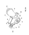
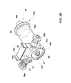
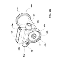
- the receptacle section 40 is in the form of a hollow barrel 42 with a pressure application end 42a at the proximal portion 40a of the receptacle and a discharge end 42b at the distal portion 40b of the receptacle.
- the pressure end 42a of the housing is open and is adapted to receive therethrough a pressure member in the form of a piston 44 ( Fig. 2B ).
- the piston 44 is formed of a substantially cylindrical portion 44a and an actuator interface 44b ( Fig. 2B ).
- the cylindrical portion 44a is formed with a groove adapted to receive therein an O-ring 45 adapted to prevent leakage of inflation fluid between the inner walls of the barrel 42 and the piston 44.
- the actuator interface 44b is adapted to be attached to an actuator (not shown in Figs. 2A to 2C ) for multi-use part the displacement of the piston 44 within the barrel 42 as will be explained in detail further on.
- the discharge end 42b of the barrel 42 is formed with a resilient diaphragm 46 having an attachment port 47, adapted for attachment thereto of a sensor (shown Fig. 3 ) for measuring the deformation of the diaphragm 46, which is mounted in the support section 20a of the base 20, as will be described in more detail below.
- the actuation section 22 has a housing 22 and disposed therein an actuator 70 shown Fig. 3 , a motor 21 and a controller (not shown) connectable to a computer and a visual display.
- the actuator 70 has one end (not seen) at which it is attached to the motor 21 and the other end 70a is formed with a ball socket 74 for detachably receiving therein the actuator interface 44b of the piston 44.
- the actuator 70 is adapted to be axially displaced within the housing 22 along the central axis X between a fully retracted position and a fully extended position in which the member 72 protrudes from the housing 22 through a hole 23 formed therein into the proximal portion 40a of the receptacle 40, thereby providing support for the proximal end 30a of the disposable part 30.
- the support section 24 extends along and is disposed below the level of the axis X, and has its one end portion 24a attached to or integrally formed with the actuation section 20a and the other end portion 24b formed with a vertically projecting support arm 25.
- the support arm 25 is formed with a tube 26 aligned with the central axis X and adapted to receive therein the distal portion 40b of the receptacle 40 with its diaphragm 46, thereby providing support for the distal end of the disposable part 30.
- the base 20 further comprises a sensing system 80 including a first load cell 82 and a second load cell 84, both adapted to measure pressure applied to inflation liquid when filling the hollow barrel 42.
- the first load cell 82 is associated with the actuator 70 to measure pressure exerted thereby on the piston 44, 70
- the second load cell 84 is positioned within the tube 26 and is adapted to be attached to the attachment port 47 of the resilient diaphragm 46 at the distal end of the receptacle 40 to measure deformation of the resilient diaphragm when pressure is applied to the inflation liquid
- Both load cells are adapted to transfer data measured thereby to the controller disposed inside the actuating section 20a of the system.
- the sensing system 80 further comprises a movement sensor (not shown) associated with the actuator 70 allowing the sensing system 80 to acquire information regarding the axial displacement of the piston 44 within the barrel 42.
- a data processing unit (not shown) positioned within the base 20 is adapted to calculate the volume V of the fluid which is transferred through the discharge end 42b of the barrel 42. It should also be noted that the volume V may be calculated in a variety of ways using data derived from a variety of sensors, for example, by measuring RPM of the motor 21 or by a sterile consumption sensor.
- the sensing system 80 as described above allows measuring pressure within the barrel 42 and volume of inflation fluid introduced into the dilatation balloon in a completely non-contact manner, wherein the inflation fluid may remain sterile.
- the support section 24 may optionally be made of a first and a second part (not shown) whereby the first part is attached to the barrel 42 and the second part is attached to the piston 44.
- the base 20 further comprises an emergency release mechanism 28 for quick release of the dilatation balloon from the blood vessel in case of a malfunction such as rupture of the balloon, rupture of the blood vessel or even in the event of a power cut.
- the release mechanism 28 operates in a completely mechanical manner and does not rely on a power supply to perform the release.
- the release mechanism 28 is manually pulled back, displacing the piston 44 and consequently draining the inflation fluid from the dilatation balloon. This may be achieved by separating the first part of the support section from the second part, thereby separating the piston 44 from the barrel 42.
- valve assembly 50 of the disposable part 30 is formed integrally with the receptacle 40 thereof.
- the valve assembly 50 comprises a storage chamber 52 with a lid 58, a channel 54 having a first end 54a and a second end 54b, and three outlets being disposed therealong 53a, 53b and 53c leading to the inlet/outlet port 49, barrel 42 and storage chamber 52 respectively.
- a switch-shaft 56 is inserted in the channel 54 and comprising a first distribution member 56a at one end thereof associated with the first end 54a of the channel 54 and a second distribution member 56b at the other end thereof associated with the second end 54b of the channel 54.
- the distribution members 56a, 56b are adapted to be attached to each other after insertion into the fluid channel 54 by a screwing engagement, and may be axially displaced along the channel 54 so as to switch from one position to another.
- the switch-shaft 56 is stepped, i.e. tubular steel shaft which tapers in a series of steps, and is fitted with four O-rings 55a to 55d respectively, adapted to prevent leakage of liquid outside the disposable part.
- the valve assembly 50 further comprises a biasing spring 57 mounted on the switch-shaft 56 between the first distribution member 56a and the side wall of the storage chamber 52 so as to bias the switch-shaft 56.
- the switch-shaft 56 is displaceable along the channel 54 by a motor (not shown) to be connected to the first distribution member 56a.
- the barrel 42 and valve 50 are integrally formed so that the outlet 53a is in fluid communication with the inlet/inlet/outlet port 49, the outlet 53b is in fluid communication with the barrel 42, and the outlet 53c is fluid communication with the storage chamber 52.
- valve assembly 50 is adapted to take several positions depending on the position of the switch-shaft 56 relative to the inlets of the channel 54 as specified below:
- Position 'd' is achieved when the switch-shaft 56 is pushed inwards, i.e. the spring 57 compresses, to such an extent that the O-rings 55c and 55d are displaced outside the channel 54, thus no longer sealing the valve assembly 50 and allowing leakage of fluid from the channel 54 to the outside environment.
- the switch-shaft 56 allows the fluid to be discharged from the barrel 42, storage chamber 52 and dilatation balloon through the second end of the channel 54b.
- the disposable part 30 is mounted on the base 20 such that the ball 44b of the piston 44 is received in the socket 74 of actuator 70, the distribution member 56a of the switch-shaft 56 is connected to another motor of the actuation section 20a and the distal end 40b of the receptacle section 40 is received within the tube 26 of the support section 20b so that the attachment port 47 becomes attached to the sensor 82.
- the supply line 60 is attached at its first end 62 to the inlet/inlet/outlet port 49 of the disposable part 40, and at its second end 64 to a supply of a contrast fluid.
- the position of the valve assembly 50 is then switched to an 'inflation/withdrawal' position and the piston 44 is displaced by the actuator 70, allowing the contrast fluid to flow into the barrel 42.
- the position of the valve assembly 50 is switched to an 'air removal' position. In this position the piston 44 is pushed forward pressuring the contrast fluid into the storage chamber 52 of the valve assembly 50 allowing excess air bubbles to be discharged from the contrast fluid to the outside environment.
- the second end 64 of the supply line 60 is attached to a supply of a diluting liquid and the position of the valve assembly 50 is again switched to the 'inflation/withdrawal' position and the diluting fluid is introduced into the barrel 42.
- the valve assembly 50 is then switched back into an 'air removal' position and the piston 44 is again pushed into the barrel 42 pressuring both fluids into the storage chamber 52. This allows the removal of air bubbles from the fluids as well as mixture of the contrast and diluting fluid to form a uniform mix.
- the uniform mix is returned into the barrel 42 by displacing the piston 44 such that the mix is entirely within the barrel 42.
- air is simultaneously withdrawn from the balloon, causing it to shrink and allowing it to assume a dimension small enough to be inserted into the desired blood vessel.
- the valve assembly 50 In order to tune the system 10 the valve assembly 50 is switched into a 'tuning' position in which fluid communication of the inlet/outlet port 49 and storage chamber 52 with the barrel 42 is blocked. The piston 44 is then displaced back and forth repeatedly, allowing the sensing system to receive data from the sensors and tune the system 10.
- a dilatation balloon (not shown) may be attached to the inlet/outlet tube 60 mounted on the inlet/outlet port 49 of the receptacle section 40.
- the valve assembly 50 may then be switched into an 'inflation/withdrawal' position and the piston 44 is pulled backwards facilitating removal of air from the dilatation balloon by withdrawing it into the barrel 42.
- the withdrawn air may be discharged through the storage chamber 52 in the 'air removal' position.
- the system 10 is ready for the inflation stage, wherein the inflation fluid is introduced into the dilatation balloon.
- the motor operates the actuator 70 such that the piston 44 is displaced along the barrel 42, thus pressing the inflation fluid into the balloon. Since the actuator 70 is both attached to the piston 44 and associated with the sensing system 80, real-time data regarding the time of inflation and the volume of the inflation fluid introduced into the balloon, and pressure within the barrel may be derived.
- the controller of the system may be programmed to automatically react to changes in pressure according to data derived from the sensing system 80. For example, a predetermined maximum pressure value may be set wherein, in case the controller receives information from the sensing system that the pressure reaches the maximum pressure, it may slow down the motor or stop it completely in order not to exceed the predetermined value.
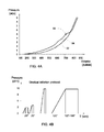
- the first P vs. V scheme 92 is a scheme produced during a standard catheterization process. It may be observed that the pressure within the balloon increases as a function of inflation fluid leaving the barrel 42. In this essence it should be noted that the sensing system receives a reading indicating the amount of fluid promoted by the piston 44 and calculating the amount of fluid within the dilatation balloon.
- the second P vs. V scheme 94 is produced during a similar catheterization system in which the blood vessel has its inner walls covered by a layer of plaque (not shown). As more inflation fluid is introduced into the balloon, the balloon exerts more and more pressure on the inner walls of blood vessel by direct contact with the plaque layer.
- the balloon may further dilate allowing more inflation fluid to pour therein, facilitating a pressure drop. This phenomenon may be clearly noticeable from the temporary slope drop in the P vs. V line 94 after point 96. Thus, when such a phenomenon is noticed the inflation rate may be automatically changed so as not to damage the blood vessel.
Landscapes
- Health & Medical Sciences (AREA)
- Life Sciences & Earth Sciences (AREA)
- Heart & Thoracic Surgery (AREA)
- Biomedical Technology (AREA)
- Biophysics (AREA)
- Pulmonology (AREA)
- Engineering & Computer Science (AREA)
- Anesthesiology (AREA)
- Child & Adolescent Psychology (AREA)
- Hematology (AREA)
- Animal Behavior & Ethology (AREA)
- General Health & Medical Sciences (AREA)
- Public Health (AREA)
- Veterinary Medicine (AREA)
- Vascular Medicine (AREA)
- Media Introduction/Drainage Providing Device (AREA)
Applications Claiming Priority (1)
| Application Number | Priority Date | Filing Date | Title |
|---|---|---|---|
| US92966707P | 2007-07-09 | 2007-07-09 |
Publications (2)
| Publication Number | Publication Date |
|---|---|
| EP2014330A2 true EP2014330A2 (fr) | 2009-01-14 |
| EP2014330A3 EP2014330A3 (fr) | 2009-03-04 |
Family
ID=39869722
Family Applications (1)
| Application Number | Title | Priority Date | Filing Date |
|---|---|---|---|
| EP08103195A Withdrawn EP2014330A3 (fr) | 2007-07-09 | 2008-03-31 | Système de gonflage/dégonflage pour cathéter |
Country Status (2)
| Country | Link |
|---|---|
| US (1) | US7981078B2 (fr) |
| EP (1) | EP2014330A3 (fr) |
Cited By (2)
| Publication number | Priority date | Publication date | Assignee | Title |
|---|---|---|---|---|
| WO2009125380A1 (fr) * | 2008-04-09 | 2009-10-15 | Flip Technologies Limited | Système et procédé pour gonfler un élément gonflable avec un milieu de gonflage liquide et cathéter à ballonnet gonflé par le système et le procédé |
| EP2598197A4 (fr) * | 2010-07-28 | 2017-02-08 | Medtronic Cryocath LP | Ballonnet cryogénique pour ablation endoluminale et procédé associé |
Families Citing this family (4)
| Publication number | Priority date | Publication date | Assignee | Title |
|---|---|---|---|---|
| US20100004595A1 (en) * | 2008-07-01 | 2010-01-07 | Ethicon, Inc. | Balloon catheter systems for treating uterine disorders having fluid line de-gassing assemblies and methods therefor |
| WO2019200201A1 (fr) | 2018-04-12 | 2019-10-17 | The Regents Of The University Of Michigan | Système pour effectuer et commander une pression oscillatoire à l'intérieur de cathéters à ballonnet pour fracture de fatigue de calculs |
| EP4288136A4 (fr) | 2021-02-04 | 2024-08-07 | Amplitude Vascular Systems, Inc. | Systèmes de cathéter à ballonnet pulsatile et leurs procédés d'utilisation |
| WO2025165434A1 (fr) * | 2024-01-30 | 2025-08-07 | St. Jude Medical, Cardiology Division, Inc. | Valvule et systèmes de délivrance pour implantation transcathéter valvule-dans-valvule |
Citations (3)
| Publication number | Priority date | Publication date | Assignee | Title |
|---|---|---|---|---|
| US5273537A (en) | 1992-03-06 | 1993-12-28 | Scimed Life Systems, Inc. | Power-assisted inflation apparatus |
| US5599301A (en) | 1993-11-22 | 1997-02-04 | Advanced Cardiovascular Systems, Inc. | Motor control system for an automatic catheter inflation system |
| US5891089A (en) | 1994-05-17 | 1999-04-06 | Hadasit Medical Research Services & Development | System and method for coronary angioplasty |
Family Cites Families (17)
| Publication number | Priority date | Publication date | Assignee | Title |
|---|---|---|---|---|
| US4651738A (en) | 1985-08-02 | 1987-03-24 | Baylor College Of Medicine | Method and device for performing transluminal angioplasty |
| US4781192A (en) | 1986-12-22 | 1988-11-01 | Baylor College Of Medicine | Balloon dilation apparatus |
| US5284480A (en) | 1990-11-09 | 1994-02-08 | Medtronic, Inc. | Inflation/deflation syringe with threaded plunger |
| FR2692791B1 (fr) | 1992-06-26 | 1998-07-24 | Aguettant Lab | Systeme de connexion sterile. |
| US5342298A (en) * | 1992-07-31 | 1994-08-30 | Advanced Cardiovascular Systems, Inc. | Automated fluid pressure control system |
| DE19602140A1 (de) * | 1995-01-30 | 1996-08-01 | Minnesota Mining & Mfg | Antegrad/retrograd-Schalter für Kardioplegiekanülen |
| IL121214A0 (en) | 1997-06-17 | 1998-01-04 | Medicard Ltd | Angioplasty pressure/volume control system |
| US6299592B1 (en) * | 1998-03-31 | 2001-10-09 | Northgate Technologies Inc. | Laparoscopic insufflator |
| DE19909654C2 (de) | 1999-01-02 | 2001-02-01 | Rolf Holthaus | Ventilanordnung zur Flußsteuerung von medizinischen Fluiden |
| US6139523A (en) | 1999-02-01 | 2000-10-31 | Merit Medical Systems, Inc. | Isolation system for pressure gauges for permitting repeated use without sterilization |
| ES2205956B1 (es) | 2000-10-16 | 2005-04-01 | Probitas Pharma S.A. | Aparato para inflado y desinflado de cateteres con balon y procedimiento de utilizacion del mismo. |
| US20020143294A1 (en) | 2001-02-14 | 2002-10-03 | Duchon Douglas J. | Catheter fluid control system |
| US6918893B2 (en) * | 2001-10-04 | 2005-07-19 | Scimed Life Systems, Inc. | Multiple port fluid control valves |
| US7497843B1 (en) * | 2004-03-12 | 2009-03-03 | Medrad, Inc. | Syringe interfaces, syringe adapters and injector systems |
| WO2007002154A2 (fr) | 2005-06-21 | 2007-01-04 | Medrad, Inc. | Systeme medical d'injection de fluide et de gonflage |
| WO2007076463A2 (fr) | 2005-12-27 | 2007-07-05 | Acist Medical Systems, Inc. | Dispositif de gonflement de ballonnet |
| WO2008042347A2 (fr) | 2006-10-02 | 2008-04-10 | President And Fellows Of Harvard College | Cathéter à ballonnet intelligent |
-
2008
- 2008-03-06 US US12/073,496 patent/US7981078B2/en not_active Expired - Fee Related
- 2008-03-31 EP EP08103195A patent/EP2014330A3/fr not_active Withdrawn
Patent Citations (3)
| Publication number | Priority date | Publication date | Assignee | Title |
|---|---|---|---|---|
| US5273537A (en) | 1992-03-06 | 1993-12-28 | Scimed Life Systems, Inc. | Power-assisted inflation apparatus |
| US5599301A (en) | 1993-11-22 | 1997-02-04 | Advanced Cardiovascular Systems, Inc. | Motor control system for an automatic catheter inflation system |
| US5891089A (en) | 1994-05-17 | 1999-04-06 | Hadasit Medical Research Services & Development | System and method for coronary angioplasty |
Cited By (3)
| Publication number | Priority date | Publication date | Assignee | Title |
|---|---|---|---|---|
| WO2009125380A1 (fr) * | 2008-04-09 | 2009-10-15 | Flip Technologies Limited | Système et procédé pour gonfler un élément gonflable avec un milieu de gonflage liquide et cathéter à ballonnet gonflé par le système et le procédé |
| US8486011B2 (en) | 2008-04-09 | 2013-07-16 | Flip Technologies Limited | System and a method for inflating an inflatable element with a liquid inflating medium and a balloon catheter inflated by the system and method |
| EP2598197A4 (fr) * | 2010-07-28 | 2017-02-08 | Medtronic Cryocath LP | Ballonnet cryogénique pour ablation endoluminale et procédé associé |
Also Published As
| Publication number | Publication date |
|---|---|
| US7981078B2 (en) | 2011-07-19 |
| EP2014330A3 (fr) | 2009-03-04 |
| US20090018499A1 (en) | 2009-01-15 |
Similar Documents
| Publication | Publication Date | Title |
|---|---|---|
| US8758294B2 (en) | Balloon inflation device | |
| US8262610B2 (en) | Catheter fluid control system | |
| US5562614A (en) | Programmable manifold system for automatic fluid delivery | |
| US7981078B2 (en) | Inflation/deflation system for a catheter | |
| US4721123A (en) | Catheter reprocessing system | |
| US5460609A (en) | Electromechanical inflation/deflation system | |
| EP2358423B1 (fr) | Système et procédé pour affichage de seringue de gonflage et ensemble de composants modularisés | |
| US5599301A (en) | Motor control system for an automatic catheter inflation system | |
| EP1199083A1 (fr) | Dispositif et procede permettant de gonfler et de degonfler cathéters à ballon | |
| US8192397B2 (en) | Medical fluid injection and inflation system | |
| EP1941914B1 (fr) | Machine à laver et à désinfecter les endoscopes et procédé pour contrôler l'administration de l'agent de nettoyage et de désinfection utlilizé dans ladite machine | |
| US5284480A (en) | Inflation/deflation syringe with threaded plunger | |
| US5009662A (en) | Medical pressure sensing and display system | |
| US5459700A (en) | Manual timer control for inflation device | |
| EP2288404B1 (fr) | Système pour une seringue de gonflage à affichage amélioré | |
| US7641668B2 (en) | Fluid delivery system and related methods of use | |
| US6179815B1 (en) | Low compliance inflation/deflation system | |
| US6254569B1 (en) | Automatic engagement and pressure checking system for an inflation control system | |
| US20090076439A1 (en) | Inflation System for Balloon Catheter | |
| JP2023519191A5 (fr) | ||
| US20240075259A1 (en) | Balloon Angioplasty Inflation Device and Method of Preparing a Balloon for Angioplasty | |
| US7052481B2 (en) | Balloon catheter inflation | |
| US20030014071A1 (en) | Inflation device and methods of use | |
| CN203724611U (zh) | 充气/放气系统 | |
| US20170043139A1 (en) | Fluid delivery or removal system |
Legal Events
| Date | Code | Title | Description |
|---|---|---|---|
| PUAI | Public reference made under article 153(3) epc to a published international application that has entered the european phase |
Free format text: ORIGINAL CODE: 0009012 |
|
| AK | Designated contracting states |
Kind code of ref document: A2 Designated state(s): AT BE BG CH CY CZ DE DK EE ES FI FR GB GR HR HU IE IS IT LI LT LU LV MC MT NL NO PL PT RO SE SI SK TR |
|
| AX | Request for extension of the european patent |
Extension state: AL BA MK RS |
|
| PUAL | Search report despatched |
Free format text: ORIGINAL CODE: 0009013 |
|
| AK | Designated contracting states |
Kind code of ref document: A3 Designated state(s): AT BE BG CH CY CZ DE DK EE ES FI FR GB GR HR HU IE IS IT LI LT LU LV MC MT NL NO PL PT RO SE SI SK TR |
|
| AX | Request for extension of the european patent |
Extension state: AL BA MK RS |
|
| 17Q | First examination report despatched |
Effective date: 20091001 |
|
| 17P | Request for examination filed |
Effective date: 20090903 |
|
| AKX | Designation fees paid |
Designated state(s): AT BE BG CH CY CZ DE DK EE ES FI FR GB GR HR HU IE IS IT LI LT LU LV MC MT NL NO PL PT RO SE SI SK TR |
|
| STAA | Information on the status of an ep patent application or granted ep patent |
Free format text: STATUS: THE APPLICATION IS DEEMED TO BE WITHDRAWN |
|
| 18D | Application deemed to be withdrawn |
Effective date: 20121002 |