EP2014338A1 - Structure d'appareil de jeu de lancer de ballon - Google Patents
Structure d'appareil de jeu de lancer de ballon Download PDFInfo
- Publication number
- EP2014338A1 EP2014338A1 EP07013559A EP07013559A EP2014338A1 EP 2014338 A1 EP2014338 A1 EP 2014338A1 EP 07013559 A EP07013559 A EP 07013559A EP 07013559 A EP07013559 A EP 07013559A EP 2014338 A1 EP2014338 A1 EP 2014338A1
- Authority
- EP
- European Patent Office
- Prior art keywords
- rim
- movable
- game device
- ball
- ball throw
- Prior art date
- Legal status (The legal status is an assumption and is not a legal conclusion. Google has not performed a legal analysis and makes no representation as to the accuracy of the status listed.)
- Withdrawn
Links
- NIXOWILDQLNWCW-UHFFFAOYSA-N acrylic acid group Chemical group C(C=C)(=O)O NIXOWILDQLNWCW-UHFFFAOYSA-N 0.000 claims description 2
- 230000013011 mating Effects 0.000 claims 3
- 238000001514 detection method Methods 0.000 description 17
- 238000000034 method Methods 0.000 description 6
- 230000008569 process Effects 0.000 description 3
- 238000003780 insertion Methods 0.000 description 2
- 230000037431 insertion Effects 0.000 description 2
- 238000012986 modification Methods 0.000 description 2
- 230000004048 modification Effects 0.000 description 2
- 230000004913 activation Effects 0.000 description 1
- 230000000903 blocking effect Effects 0.000 description 1
- 238000010276 construction Methods 0.000 description 1
- 230000008878 coupling Effects 0.000 description 1
- 238000010168 coupling process Methods 0.000 description 1
- 238000005859 coupling reaction Methods 0.000 description 1
- 230000000694 effects Effects 0.000 description 1
- 230000002708 enhancing effect Effects 0.000 description 1
- 230000004044 response Effects 0.000 description 1
- 238000004088 simulation Methods 0.000 description 1
- 238000006467 substitution reaction Methods 0.000 description 1
- 230000000007 visual effect Effects 0.000 description 1
Images




Classifications
-
- A—HUMAN NECESSITIES
- A63—SPORTS; GAMES; AMUSEMENTS
- A63B—APPARATUS FOR PHYSICAL TRAINING, GYMNASTICS, SWIMMING, CLIMBING, OR FENCING; BALL GAMES; TRAINING EQUIPMENT
- A63B67/00—Sporting games or accessories therefor, not provided for in groups A63B1/00 - A63B65/00
- A63B67/06—Ring or disc tossing games, e.g. quoits; Throwing or tossing games, e.g. using balls; Games for manually rolling balls, e.g. marbles
-
- A—HUMAN NECESSITIES
- A63—SPORTS; GAMES; AMUSEMENTS
- A63B—APPARATUS FOR PHYSICAL TRAINING, GYMNASTICS, SWIMMING, CLIMBING, OR FENCING; BALL GAMES; TRAINING EQUIPMENT
- A63B63/00—Targets or goals for ball games
- A63B63/06—Revolving targets ; Moving targets, e.g. moving or revolving on impact
-
- A—HUMAN NECESSITIES
- A63—SPORTS; GAMES; AMUSEMENTS
- A63B—APPARATUS FOR PHYSICAL TRAINING, GYMNASTICS, SWIMMING, CLIMBING, OR FENCING; BALL GAMES; TRAINING EQUIPMENT
- A63B63/00—Targets or goals for ball games
- A63B63/08—Targets or goals for ball games with substantially horizontal opening for ball, e.g. for basketball
- A63B63/083—Targets or goals for ball games with substantially horizontal opening for ball, e.g. for basketball for basketball
-
- A—HUMAN NECESSITIES
- A63—SPORTS; GAMES; AMUSEMENTS
- A63B—APPARATUS FOR PHYSICAL TRAINING, GYMNASTICS, SWIMMING, CLIMBING, OR FENCING; BALL GAMES; TRAINING EQUIPMENT
- A63B69/00—Training appliances or apparatus for special sports
- A63B69/0071—Training appliances or apparatus for special sports for basketball
-
- A—HUMAN NECESSITIES
- A63—SPORTS; GAMES; AMUSEMENTS
- A63B—APPARATUS FOR PHYSICAL TRAINING, GYMNASTICS, SWIMMING, CLIMBING, OR FENCING; BALL GAMES; TRAINING EQUIPMENT
- A63B63/00—Targets or goals for ball games
- A63B2063/001—Targets or goals with ball-returning means
-
- A—HUMAN NECESSITIES
- A63—SPORTS; GAMES; AMUSEMENTS
- A63B—APPARATUS FOR PHYSICAL TRAINING, GYMNASTICS, SWIMMING, CLIMBING, OR FENCING; BALL GAMES; TRAINING EQUIPMENT
- A63B2225/00—Miscellaneous features of sport apparatus, devices or equipment
- A63B2225/70—Coin-operated
Definitions
- the present invention relates to a ball throw game device, and in particular to a ball throw game device having a back stop that is movable in front-rear direction, left-right direction, and up-down direction.
- a ball throw game device is commonly seen in a playground or an entertainment court.
- a conventional ball throw game device as shown in Figure 1 of the attached drawings, generally designated at 1, comprises a chassis 10 in which electronic control circuits (not shown) are provide; an inclined ball supply chute 11 formed in the chassis 10; a backboard 12 that constitutes in part a back stop structure and arranged upright at an internal end of the chute 11; a rim hoop ring 13, with a net attached thereto, mounted to a front face of the backboard 12; a score display 14 that is located in front of the rim hoop ring 13 and above the chute 11 for display of the score won by a player; a ball blockade (not shown) arranged in the chute 11 and controlled by the electronic control circuit to close/open the chute 11 for selectively blocking a plurality of balls 15, such as basketballs, that are fed through the chute 11 until the chute 11 is opened; and a coil slot 16 for receiving coins that activate the operation of the ball throw device.
- the rim hoop ring 13 is provided with a sensor (not shown) that is electrically connected to the electronic control circuit for detecting a ball passing through the rim hoop ring 13.
- the electronic control circuit is operated under the control of a time delay device (not shown), which maintain the activation of the electronic control circuit unit a preset time period determined by the time delay device is used up, when the ball throw game device is de-activated and a cycle of ball throw process is completed. To start another cycle of ball throw, new coins are needed to deposit into the coil slot 16 to re-activate the game device.
- a user may stand in front of the game device 1 and deposit a sufficient number of coins into the coin slot 16, and then the electronic control circuit inside the chassis 10 is activated to open the ball blockade within the chute 11, thereby releasing the balls 15 that are originally confined behind the ball blockade, so that balls 15 roll to the user.
- the electronic control circuit activates and resets the display 14 to a ready-to-count condition.
- the user may start to pickup and throw the ball 15 to the rim hoop ring 13.
- the sensor mounted on the rim hoop ring 13 sends out a signal to the electronic control circuit, which, in response to the signal, shows up a score on the display 14.
- the conventional ball throw device 1 is constructed with a fixed rim hoop ring 13, which is maintained at a fixed altitude with respect to the chassis 11 and is also kept stationary.
- a fixed rim hoop ring 13 which is maintained at a fixed altitude with respect to the chassis 11 and is also kept stationary.
- an industrious player after several times of practicing, may soon get familiar with ball throw trajectories that lead the ball to pass through the rim hoop ring 13 due to the fixed altitude and distance of the rim hoop ring 13. Consequently, the shot rate can be significantly improved and score gained can be increased quickly. This makes the game no long challengeable to the players and the fun of playing the ball throw game is lessened.
- the present invention is aimed to provide a ball throw game device that overcomes the drawbacks of the conventional ball throw game devices.
- the primary purpose of the present invention is to provide a ball throw game device that overcomes the drawback of the conventional game device that rim hoop rings for ball shot are fixed, thereby lacking challenge and entertainment effect.
- a ball throw game device comprises containments walls arranged on opposite sides and at a front side and an inclined board is arranged between the containment walls to form a ball collection zone.
- An inclined top is provided above the ball collection zone and supports a data display and a game stage display to provide indication or display of data to a player so that the player may get aware of the score that he or she gains and the types or modes of game that is being carried out.
- a coin slot is formed below the ball collection zone.
- a ball throw game device comprises a chassis, a movable rack, a first rim set, a second rim set, and a third rim set.
- the movable rack has a power unit that drives the movable rack to move in front-rear direction.
- the first rim set is movable in front-rear direction by being driven by a power unit.
- the second rim set is movable in left-right direction by being driven by a power unit.
- the third rim set is movable in up-down direction by being driven by a power unit.
- ball shot skill of a player can be enhanced by the movements of rim hoop rings carried by the first, second, and third rim sets in the front-rear, left-right, and up-down direction.
- practicing of ball shot and entertainment of the game can be significantly enhanced.
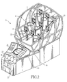
- the ball throw game device 2 comprises containment walls 21 on opposite sides and a front side.
- the containment walls 21 can be made of transparent or light-transmitting boards.
- an interior space is formed and is further delimited by an inclined board 22 that guides ball B toward a ball collection zone 23.
- An inclined top 24 is arranged above the ball collection zone 23 and a data display 25 and a game stage display 25 are arranged on the top 24 to indicate the score gained by a player and the operation status to the player.
- a coin slot 27 is provided below the ball collection zone 23
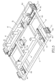
- inside structure of the ball throw game device 2 comprises at least a chassis 3, a movable rack 4, a first rim set 5, a second rim set 6, and a third rim set 7.
- the chassis 3 is constructed as a framework.
- a first slide track set 31 comprises two first slide tracks provided on opposite sides and arranged symmetrically. In the embodiment illustrated, the first slide tracks 31 may comprises linear rails.
- a power unit 32 is provided on the framework of the chassis 3 and is in operative coupling with the movable rack 4.
- the movable rack 4 comprises two side bars 41 that are arranged between the first slide tracks 31.
- Each side bar 41 is provided with a fixing plate 4111, to which a first slide block 311 of each first slide track 31 and a padding board 312 are mounted.
- a second slide track set 42 which may comprise two second slide tracks, is mounted on the movable rack 4.
- a detection plate 43 which is detectable by a detection device 33 mounted to the chassis 3, is mounted to the movable rack 4.
- the detection device 43 comprises sensors 331,332.
- the power unit 32 moves the movable rack 4 in a frontward direction
- the power unit 33 moves the movable rack 4 in a rearward direction and thus the movable rack 4 is reciprocally movable in the frontward and rearward directions in this way.
- the movable rack 4 is also provided with a third slide track set 44, a crossbar 45, and a power unit 46.
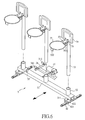
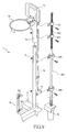
- the first rim set 5 comprises a movable base 51, which forms on an underside thereof at locations close to opposite ends fixing plates 511 respectively, each secured to slide blocks 421 and padding plates 422 of each second slide track 42.
- a number of cylindrical sleeves 52 are formed on the movable base 51 for each receiving insertion of a support stalk 53.
- Each support stalk 53 supports a backboard 54, a rim hoop ring 55, and a bracket 56, as shown in Figure 6 .
- the backboard 54 is secured to the bracket 56 by threaded fasteners.
- the rim hoop ring 55 forms an extension plate 551 that is secured to the bracket 56.
- the bracket 56 itself is fixed to an upper end of the stalk 53.
- a mirror-surfaced reflection detector 561 is mounted below the bracket 56 and a tab 552 is mounted to the rim hoop ring 55 at a location exactly opposite to the mirror-surfaced reflection detector 561.
- a reflective pad 553 is mounted to the tab 552.
- the movable base 51 of the first rim set 5 is operatively coupled to the power unit 46 so that the power unit 46 drives the movable base 51 to reciprocates along the second slide tracks 42 in the front-rear direction.
- the fixing plate 511 is provided with a detection plate 57 that is detectable by sensors 341, 342 of a detection device 34 mounted on the chassis 3.
- the second rim set 6 comprises a movable bar 61 that is movably mounted on a third slide track set 44 of the movable rack 4.
- the movable bar 61 forms on an underside thereof at locations close to opposite ends fixing plates 611 that are secured to slide blocks 441 and padding plates 442 of the third slide track set 44.
- a plurality of cylindrical sleeves 62 is formed on the movable bar 61 for each receiving insertion of a support stalk 63.
- the movable rack 4 is further provided with a power unit 47 that is operatively coupled to the movable bar 61 so that the power unit 46 drives the movable bar 61 to move in rightward/leftward direction along the third slide track set 44.
- the movable bar 61 is provided with a detection plate 64 that is detectable by sensors 351, 352, 353 of a detection device 35 mounted on the chassis 3.
- the cylindrical sleeves 62 of the movable bar 61 receive and support the support stalks 63 and each support stalk 63 supports a backboard 65, a rim hoop ring 66, and a bracket 67.
- the backboard 65, the rim hoop ring 66, and the bracket 67 are respectively of the same structures as those of the backboard 54, the rim hoop ring 55, and the bracket 56 of the first rim set 5 so that no further details are needed herein.
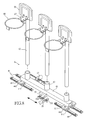
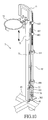
- the third rim set 7 comprises a plurality of third support stalks 71 mounted to the crossbar 45 of the movable rack 4.
- An upper end of each support stalk 71 is movably fit into a movable sleeve 72 and the sleeve 72 supports a backboard 73, a rim hoop ring 74, and a bracket 75.
- the backboard 73, the rim hoop ring 74, and the bracket 75 are respectively of the same structures as those of the backboard 54, the rim hoop ring 55, and bracket 56 of the first rim set 5 so that no further details are needed herein.
- the third rim set 7 further comprises a power unit 48 mounted to the crossbar 45.
- the power unit 48 is operatively coupled to a shaft 481 having an upper end portion forming a threaded rod 482.
- a plurality of nut members 483 is fit over and threadingly engages the threaded rod 482 and is fixed to the sleeve 72.
- a plurality of bearings 484 are mounted to the shaft 481 and are fixed to support stalk 71.
- the sleeve 72 is provided with a long rod 76 having a lower end to which a detection plate 77 is mounted. The detection plate 77 is detectable by sensors 361, 362 of a detection device 36.
- a player puts a sufficient number of coins into the coin slot 27 and the electronic control circuit of the game device 2 is activated, which starts the data display 25 in a reset condition for being ready to count.
- the game thus starts and according to previous settings of the electronic control circuit, with the detection plate 57 of the movable base 51 of the first rim set 5 being detectable by the sensors 341, 342 of the detection device 34, the movable base 51 is driven by the power unit 46 to move reciprocally along the second slide tracks 42 in the front-rear direction.
- the second rim set 6 When ball shot for the first rim set 5 is completed, the second rim set 6, with the movable bar 61 being detectable by the sensors 351, 352, 353 of the detection device 35 that is mounted to the chassis 3, is driven by the power unit 47 to move reciprocally along the slide tracks 44 in the left-right direction.
- the power unit 48 of the third rim set 7 is activated and the shafts 481 and the threaded rods 482 are driven to rotate, whereby the threaded rods 482 cause the sleeves 72 to move reciprocally in the up-down direction.
- the first rim set 5, the second rim set 6, and the third rim set 7 are together moved with the movable rack 4 to enhance the difficult of ball shot and the challengeability and amusement of the game.
- the backboards 54, 65, 73 of the game device 2 of the present invention can be made of clear or transparent or light-transmitting material, such as clear acrylic board, or can be made of a light guide board cooperating with a lighting source, such as cold-cathode tube or fluorescent cold cathode lamp, to generate different lighting visual effect.
- the lighting source can be electrically connected to and controlled by the electronic control circuit so that lighting of the backboards is controlled in a desired fashion to for example indicate a player to proceed with the game and thus enhancing interesting of the game.
- the effectiveness of the game device 2 of the present invention resides in that a plurality of rim sets is included, among which the first rim set 5 is made movable in the front-rear direction in a controlled manner, the second rim set 6 is movable in the left-right direction similarly in a controlled manner, and the third rim set 7 is made movable in the up-down direction also in a controlled manner, and all the rim sets 5, 6, 7 may be moved together with the movable rack 4 in the front-rear direction, and in addition, indication of ball shot can be arbitrarily provided to a player, whereby simulation of ball shot at different angles, different altitudes, and different distances can be done to enhance the difficult of ball shot and entertainment for ball shot.
Landscapes
- Health & Medical Sciences (AREA)
- General Health & Medical Sciences (AREA)
- Physical Education & Sports Medicine (AREA)
- Pinball Game Machines (AREA)
Priority Applications (1)
| Application Number | Priority Date | Filing Date | Title |
|---|---|---|---|
| EP07013559A EP2014338A1 (fr) | 2007-07-11 | 2007-07-11 | Structure d'appareil de jeu de lancer de ballon |
Applications Claiming Priority (1)
| Application Number | Priority Date | Filing Date | Title |
|---|---|---|---|
| EP07013559A EP2014338A1 (fr) | 2007-07-11 | 2007-07-11 | Structure d'appareil de jeu de lancer de ballon |
Publications (1)
| Publication Number | Publication Date |
|---|---|
| EP2014338A1 true EP2014338A1 (fr) | 2009-01-14 |
Family
ID=38739939
Family Applications (1)
| Application Number | Title | Priority Date | Filing Date |
|---|---|---|---|
| EP07013559A Withdrawn EP2014338A1 (fr) | 2007-07-11 | 2007-07-11 | Structure d'appareil de jeu de lancer de ballon |
Country Status (1)
| Country | Link |
|---|---|
| EP (1) | EP2014338A1 (fr) |
Cited By (2)
| Publication number | Priority date | Publication date | Assignee | Title |
|---|---|---|---|---|
| WO2011096184A1 (fr) * | 2010-02-04 | 2011-08-11 | ビーエルデーオリエンタル株式会社 | Dispositif de basketball |
| CN108543289A (zh) * | 2018-04-09 | 2018-09-18 | 程可航 | 一种多功能投篮机 |
Citations (4)
| Publication number | Priority date | Publication date | Assignee | Title |
|---|---|---|---|---|
| US4266763A (en) * | 1977-09-01 | 1981-05-12 | Collins Andrew P | Recreational basketball apparatus with moving backboards |
| US5842699A (en) * | 1996-09-12 | 1998-12-01 | Coastal Amusements, Inc. | Basketball game apparatus |
| US6536770B1 (en) * | 2000-08-31 | 2003-03-25 | P & P Idea Co., Ltd. | Intelligent basketball game assembly |
| US6780129B1 (en) * | 2000-06-27 | 2004-08-24 | Yugen Kaisha Digital Nine | Basketball game system |
-
2007
- 2007-07-11 EP EP07013559A patent/EP2014338A1/fr not_active Withdrawn
Patent Citations (4)
| Publication number | Priority date | Publication date | Assignee | Title |
|---|---|---|---|---|
| US4266763A (en) * | 1977-09-01 | 1981-05-12 | Collins Andrew P | Recreational basketball apparatus with moving backboards |
| US5842699A (en) * | 1996-09-12 | 1998-12-01 | Coastal Amusements, Inc. | Basketball game apparatus |
| US6780129B1 (en) * | 2000-06-27 | 2004-08-24 | Yugen Kaisha Digital Nine | Basketball game system |
| US6536770B1 (en) * | 2000-08-31 | 2003-03-25 | P & P Idea Co., Ltd. | Intelligent basketball game assembly |
Cited By (3)
| Publication number | Priority date | Publication date | Assignee | Title |
|---|---|---|---|---|
| WO2011096184A1 (fr) * | 2010-02-04 | 2011-08-11 | ビーエルデーオリエンタル株式会社 | Dispositif de basketball |
| CN108543289A (zh) * | 2018-04-09 | 2018-09-18 | 程可航 | 一种多功能投篮机 |
| CN108543289B (zh) * | 2018-04-09 | 2019-10-22 | 程可航 | 一种多功能投篮机 |
Similar Documents
| Publication | Publication Date | Title |
|---|---|---|
| TW309438B (fr) | ||
| US7361104B2 (en) | Automated ball game training and playing system | |
| JP5312573B2 (ja) | ゴルフゲーム装置 | |
| CN104274970B (zh) | 游戏机 | |
| US20090069123A1 (en) | Sports apparatus | |
| US20090163261A1 (en) | Shooting game | |
| US11276269B2 (en) | Amusement game machine and method of play having a transmissive electronic display panel overlying play field | |
| US20140300054A1 (en) | Amusement game with rotating target | |
| AU2022201361A1 (en) | Sporting or amusement apparatus | |
| US3784207A (en) | Golf game | |
| EP2014338A1 (fr) | Structure d'appareil de jeu de lancer de ballon | |
| CN201410272Y (zh) | 新型篮球架 | |
| JP5746743B2 (ja) | メダルゲーム機 | |
| US20240185666A1 (en) | Virtual attendant game machine | |
| KR20080005724U (ko) | 볼 투척 게임 장치의 구조 | |
| JP5813348B2 (ja) | ゲーム用媒体、およびこのゲーム用媒体を用いて構成されたゲーム機 | |
| JP5512777B2 (ja) | メダルゲーム機 | |
| JP3136891U (ja) | バスケットボール機構造 | |
| JP5732269B2 (ja) | ゲーム装置 | |
| CN201020249Y (zh) | 九宫篮球机 | |
| US12525091B2 (en) | Virtual attendant game machine | |
| EP1866040A1 (fr) | Appareil de sport | |
| JP5563040B2 (ja) | メダルゲーム機 | |
| CN218516108U (zh) | 一种布艺玩具投球机 | |
| CN210813800U (zh) | 一种新型投篮机 |
Legal Events
| Date | Code | Title | Description |
|---|---|---|---|
| PUAI | Public reference made under article 153(3) epc to a published international application that has entered the european phase |
Free format text: ORIGINAL CODE: 0009012 |
|
| AK | Designated contracting states |
Kind code of ref document: A1 Designated state(s): AT BE BG CH CY CZ DE DK EE ES FI FR GB GR HU IE IS IT LI LT LU LV MC MT NL PL PT RO SE SI SK TR |
|
| AX | Request for extension of the european patent |
Extension state: AL BA HR MK RS |
|
| AKX | Designation fees paid | ||
| STAA | Information on the status of an ep patent application or granted ep patent |
Free format text: STATUS: THE APPLICATION IS DEEMED TO BE WITHDRAWN |
|
| 18D | Application deemed to be withdrawn |
Effective date: 20090715 |
|
| REG | Reference to a national code |
Ref country code: DE Ref legal event code: 8566 |