EP2014370B1 - Hache - Google Patents
Hache Download PDFInfo
- Publication number
- EP2014370B1 EP2014370B1 EP07013649.4A EP07013649A EP2014370B1 EP 2014370 B1 EP2014370 B1 EP 2014370B1 EP 07013649 A EP07013649 A EP 07013649A EP 2014370 B1 EP2014370 B1 EP 2014370B1
- Authority
- EP
- European Patent Office
- Prior art keywords
- axis
- rotation
- feed pipe
- shredding device
- shredder
- Prior art date
- Legal status (The legal status is an assumption and is not a legal conclusion. Google has not performed a legal analysis and makes no representation as to the accuracy of the status listed.)
- Not-in-force
Links
Images
Classifications
-
- B—PERFORMING OPERATIONS; TRANSPORTING
- B02—CRUSHING, PULVERISING, OR DISINTEGRATING; PREPARATORY TREATMENT OF GRAIN FOR MILLING
- B02C—CRUSHING, PULVERISING, OR DISINTEGRATING IN GENERAL; MILLING GRAIN
- B02C18/00—Disintegrating by knives or other cutting or tearing members which chop material into fragments
- B02C18/06—Disintegrating by knives or other cutting or tearing members which chop material into fragments with rotating knives
- B02C18/08—Disintegrating by knives or other cutting or tearing members which chop material into fragments with rotating knives within vertical containers
- B02C18/12—Disintegrating by knives or other cutting or tearing members which chop material into fragments with rotating knives within vertical containers with drive arranged below container
-
- B—PERFORMING OPERATIONS; TRANSPORTING
- B02—CRUSHING, PULVERISING, OR DISINTEGRATING; PREPARATORY TREATMENT OF GRAIN FOR MILLING
- B02C—CRUSHING, PULVERISING, OR DISINTEGRATING IN GENERAL; MILLING GRAIN
- B02C18/00—Disintegrating by knives or other cutting or tearing members which chop material into fragments
- B02C18/06—Disintegrating by knives or other cutting or tearing members which chop material into fragments with rotating knives
- B02C18/16—Details
- B02C18/22—Feed or discharge means
- B02C18/2225—Feed means
- B02C18/2291—Feed chute arrangements
-
- B—PERFORMING OPERATIONS; TRANSPORTING
- B02—CRUSHING, PULVERISING, OR DISINTEGRATING; PREPARATORY TREATMENT OF GRAIN FOR MILLING
- B02C—CRUSHING, PULVERISING, OR DISINTEGRATING IN GENERAL; MILLING GRAIN
- B02C2201/00—Codes relating to disintegrating devices adapted for specific materials
- B02C2201/06—Codes relating to disintegrating devices adapted for specific materials for garbage, waste or sewage
- B02C2201/066—Codes relating to disintegrating devices adapted for specific materials for garbage, waste or sewage for garden waste
Definitions
- the invention relates to a shredder specified in the preamble of claim 1 genus.
- a garden shredder which has a comminution device driven about an approximately perpendicular axis of rotation, namely a cutting tool and a precutting tool.
- the shredder has a vertical feed pipe for the supply of shredded material.
- another oblique feed pipe is provided.
- the design of the chopper with two feed tubes is relatively expensive. If the operator guides branches or the like over the vertical feed pipe, no optimal chopping result is achieved. It can come to kickback effects.
- the DE 31 39 788 A1 shows a shredder for waste with a crushing area in which several cutting tools are arranged.
- the crushing area designed as a pipe feed opens in an inclined position.
- the crushing area is in a vertical pipe section formed, which adjoins the inlet.
- Shredded material that enters the shredding area through the inlet hits the cutting tools at an angle due to the inclined position of the pipe.
- Another embodiment provides a vertically arranged inlet, which opens off-center into the crushing chamber. About this inlet is only a vertical feeding of waste on the crushing tools possible.
- the invention has for its object to provide a shredder of the generic type, which is simple and with which a good crushing result can be achieved.
- shredded material such as leaves or the like should reach the shredding device almost vertically.
- An oblique impact of the cuttings on the shredding device is advantageous.
- kickback effects can be avoided.
- the lower, parallel to the axis of rotation of the crushing device section causes shredded material passes approximately perpendicular to the shredding device.
- the inclined portion leads branches or the like obliquely to the crushing device.
- the lower section is crossed by branches or the like obliquely.
- the lower portion of the feed tube is fixed to a housing of the chopper, and the inclined portion connects to the lower portion. It is provided that the lower portion of the feed tube has a length which is at least 20%, in particular at least 25% of the diameter of the feed tube. With a length of the lower portion of the feed tube of at least 20% of the diameter of the feed tube, an approximately vertical impingement of shredded material can be achieved on the feeder, even if the shredded material was passed through an inclined portion of the feed tube prior to entering the lower portion.
- the inclined portion is inclined at an angle to the rotational axis of the crusher, which is from 20 ° to 70 °, in particular from 30 ° to 60 °.
- this angle of the inclined section advantageously corresponds approximately to the angle at which branches or the like to be shredded are to be fed to the comminuting device in order to achieve a good comminution result.
- the angle of the inclined. Section specifies the angle at which branches or the like impinge on the crusher. It is provided that the inclined portion has a length which is at least 120%, in particular at least 175% of the diameter of the feed tube.
- the large length of the inclined portion relative to the diameter ensures that branches or the like are fed to the shredding device substantially parallel to the longitudinal central axis of the feed pipe. This ensures a good crushing result.
- the large length of the inclined portion prevents user intervention in the crusher.
- the length of the inclined portion and the lower portion are measured in each case at the shortest point of each section, with a bent Tube so to the inside of the bend. Depending on the inclination of the inclined portion, the outer sides of the pipe sections are correspondingly longer.
- a feed hopper is arranged on the feed tube, the upper edge is advantageously substantially flat.
- the upper edge of the hopper is approximately perpendicular to the axis of rotation of the crushing device.
- the hopper simplifies the filling of shredded material into the feed pipe. Characterized in that the upper edge is approximately perpendicular to the axis of rotation of the crushing device, that is approximately perpendicular to the effective direction of gravity, the hopper can be filled well. Shredded material filled in the hopper remains in the hopper and can not escape from the hopper at a lower position as in the case of an inclined hopper.
- the upper edge of the hopper is provided with an uneven contour or at least partially formed obliquely.
- the hopper is fixed to the inclined portion of the feed tube.
- the upper connection point of the inclined portion with the hopper is particularly seen in the effective direction of gravity outside the lower portion of the feed tube.
- the shredding device is a knife disc. It is envisaged that the imaginary extension of the lower longitudinal line of the inclined portion of the feed tube occurs at an impact point on the cutter disc which is less than two-thirds, in particular less than half the radius of the cutter disc from the axis of rotation of the cutter disc. This configuration allows most of the branches fed over the inclined section to impact the knife wheel and not abut a wall of the lower section. As a result, branches or the like can be fed well to the cutter disk despite the approximately vertical lower portion.
- the axis of rotation of the comminution device is approximately parallel to the effective direction of gravity.
- an arrangement is designated in which shredded material falls over the lower portion substantially perpendicular to the shredding device.
- the angle between the axis of rotation and effective direction of gravity is advantageously less than 10 °, in particular less than 5 °.
- the design of the feed tube from a lower, approximately vertical section and an upper inclined section thus combines the advantages of an inclined feed tube with the advantages of a vertical feed tube. Both shredded material and material to be shredded can be supplied via a common feed tube.
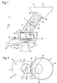
- the in Fig. 1 shown chopper 1 is designed as a garden shredder. It has a housing 2, in which a drive motor 7 is arranged.
- the drive motor 7 is in particular an electric motor.
- the drive motor 7 may also be an internal combustion engine, for example a two-stroke engine or a four-stroke engine.
- the drive motor 7 has a drive shaft 8, on which a cutter disk 10 is fixed against rotation. Instead of the cutter disk 10 may also be provided another shredding device. Also several shredders may be advantageous.
- the drive shaft 8 rotates with the cutter disk 10 about an axis of rotation 9.
- the axis of rotation 9 is approximately parallel to the effective direction 20 of gravity.
- the axis of rotation 9 with respect to the effective direction 20 of gravity may also be slightly inclined.
- the axis of rotation 9 In normal working position of the chopper 1 when set up on level ground shredder 1, the axis of rotation 9 is approximately parallel to the effective direction 20 of gravity. In this case, an angle of a few degrees between the axis of rotation 9 and the effective direction 20 of gravity can be provided.
- the advantage is the Angle between the axis of rotation 9 and the direction of action 20 less than 10 °, in particular less than 5 °.
- the cutting blades 11 are approximately in the plane of the cutter disk 10 and are arranged adjacent to the circumference of the cutter disk 10.
- the cutting blades 11 are provided for shredding branches or the like.
- the razor 12 are arranged in the center of the cutter disk 10.
- the razor 12 stand out of the plane of the knife disc 10 upwards and are provided for chopping shredded material such as leaves or the like.
- the housing 2 has an ejection 22, via the shredded material leaves the housing 2 of the chopper 1.
- a feed pipe 3 On the housing 2 of the chopper 1, a feed pipe 3 is fixed.
- the feed tube 3 has a lower portion 4, whose longitudinal central axis 13 is approximately parallel to the axis of rotation 9 of the cutter disc 10.
- the axis of rotation 9 and the longitudinal central axis 13 coincide.
- At the lower portion 4 is followed by an inclined portion 5 on the opposite side of the housing 2.
- the longitudinal center axis 14 of the inclined portion 5 includes with the axis of rotation 9 of the cutter disc 10 an angle ⁇ , which is advantageously from 20 ° to 70 °.
- the angle ⁇ is from 30 ° to 60 °.
- an angle ⁇ of about 35 ° is provided.
- a hopper 6 is arranged at the upper end 25 of the inclined portion 5.
- the hopper 6 has an upper edge 21 which is flat.
- the upper edge 21 is in particular circular. However, it can also be a deviating form, for example, an oval design, be advantageous.
- the upper edge 21 is approximately parallel to the plane of the cutter disk 10 and approximately perpendicular to the axis of rotation 9 of the cutter disk 10th
- the feed tube 3 has a diameter d which is approximately equal for the lower portion 4 and the inclined portion 5.
- the diameter d is advantageously slightly larger than the diameter of the cutter disk 10.
- the diameter of the cutter disk 10 corresponds to the double in Fig. 2 shown radius r of the cutter disk 10th
- the lower portion 4 of the feed tube 3 has a lower edge 15 which is fixed to the housing 2.
- the lower section 4 has a length a measured parallel to the longitudinal central axis 13, which is advantageously at least 20% and in particular at least 25% of the diameter d of the feed tube 3. In the exemplary embodiment, the length a is about 30% of the diameter d.
- the upper edge 26 of the lower portion 4 of the feed tube 3 is inclined relative to the lower edge 15, by an angle which corresponds to approximately half the angle ⁇ . At the upper edge 26, the inclined section 5 connects.
- the length a is measured in the region of the lower portion 4 which has the smallest length. The length a corresponds to the distance of the lower edge 15 to a lower connection point 17 between the lower portion 4 and the inclined portion 5.
- the lower connection point is the lowest lying at a vertical lower portion 4 connection point of the two sections 4, 5.
- the distance b between the lower edge 15 and an upper connection point 16 between the lower portion 4 and the inclined portion 5 is considerably larger than the length a.
- the distance b may be, for example, about 60% of the diameter d of the feed tube 3.
- the inclined portion 5 has a length f measured parallel to the longitudinal center axis 14, which is measured between the lower connection point 17 and an upper end 25 of the inclined portion 5 and which is advantageously at least 120% and in particular at least 175% of the diameter d of the feed tube 3.
- the length f is more than twice the diameter d of the feed tube 3.
- the diameter of the lower portion 4 advantageously corresponds to the diameter d of the inclined portion 5. However, it may also be provided that the lower portion 4 has a larger diameter than the inclined portion 5. Also deviating from the circular shape, for example an oval cross-section can be beneficial. In this case, the advantageous details for the length ratios and distances relate to an average diameter.
- the length f of the inclined portion 5 is considerably larger than the length a of the lower portion 4. In the embodiment, the length f is more than 6 times the length a.
- the upper connection point 19 of the inclined portion 5 with the hopper 6 has to the lower connection point 17 of the lower portion 4 with the inclined portion 5 a lateral offset c.
- Fig. 2 shows, lies the Upper connection point 19 in the effective direction 20 of gravity, ie approximately parallel to the axis of rotation 9 of the blade 10 seen outside the lower portion 4 of the feed tube 3. This is a penetration of branches or the like.
- the inclination of the inclined portion 5 is chosen so that an imaginary extension of a lower longitudinal line 18 of the inclined portion 5 impinges on the cutter disk 10.
- the point of impact 24 of the imaginary extension of the longitudinal line 18 has a distance e from the axis of rotation 9 of the cutting disc 10, which is smaller than two thirds of the radius r of the cutting disc 10 ( Fig. 2 ).
- the distance e is in particular less than half the radius r.
- the lower longitudinal line 18 is the line connecting the lower connection point 17 parallel to the longitudinal central axis 14 of the inclined portion 5 with the upper end 25 of the inclined portion 5.
- the housing 2 has two locking buttons 23, with which the housing 2 is opened and an upper portion of the housing 2 can be pivoted together with the feed tube 3 and the hopper 6 to the outside.
- the pivoting movement takes place about a pivot axis 27. After the pivoting away of the feed tube 3, the cutter disk 10 is easily accessible, for example, for cleaning purposes.
Landscapes
- Engineering & Computer Science (AREA)
- Food Science & Technology (AREA)
- Crushing And Pulverization Processes (AREA)
Claims (9)
- Broyeur avec un moteur d'entraînement (7) qui entraîne en rotation sur un axe de rotation (9) un dispositif de désintégration, le broyeur (1) comportant un tube d'amenée (3) pour amener dans le dispositif de désintégration un produit à broyer,
caractérisé en ce que le tube d'amenée (3) comporte une section inférieure (4) dont l'axe longitudinal médian (13) est disposé à peu près parallèlement à l'axe de rotation (9) du dispositif de désintégration, de sorte que le produit à broyer arrive à peu près à la verticale sur le dispositif de désintégration, et en ce que le tube d'amenée comporte une section inclinée (5) dont l'axe longitudinal médian (14) est incliné par rapport à l'axe de rotation (9) du dispositif de désintégration, une trémie de chargement (6) étant disposée sur la section inclinée (5), et le point de liaison supérieur (19) de la section inclinée (5) avec la trémie de chargement (6), vu dans le sens d'action (20) de la gravité, se trouvant en dehors de la section inférieure (4) du tube d'amenée (3). - Broyeur selon la revendication 1,
caractérisé en ce que la section inférieure (4) du tube d'amenée (3) est fixée à un carter (2) du broyeur (1), et en ce que la section inclinée (5) fait suite à ladite section inférieure (4). - Broyeur selon la revendication 1 ou 2,
caractérisé en ce que la section inférieure (4) du tube d'amenée (3) a une longueur (a) qui représente au moins 20%, en particulier au moins 25% du diamètre (d) du tube d'amenée (3). - Broyeur selon l'une des revendications 1 à 3,
caractérisé en ce que la section inclinée (5) est inclinée par rapport à l'axe de rotation (9) du dispositif de désintégration suivant un angle (α) qui est de 20° à 70°, en particulier de 30° à 60°. - Broyeur selon l'une des revendications 1 à 4,
caractérisé en ce que la section inclinée (5) a une longueur (f) qui représente au moins 120%, en particulier au moins 175% du diamètre (d) du tube d'amenée (3). - Broyeur selon l'une des revendications 1 à 5,
caractérisé en ce que le bord supérieur (21) de la trémie de chargement (6) est globalement plan et est en particulier à peu près perpendiculaire à l'axe de rotation (9) du dispositif de désintégration. - Broyeur selon l'une des revendications 1 à 6,
caractérisé en ce que le dispositif de désintégration est un disque à lames (10). - Broyeur selon la revendication 7,
caractérisé en ce que le prolongement imaginaire de l'axe longitudinal inférieur (18) de la section inclinée (5) du tube d'amenée (3) arrive sur le disque à lames (10) au niveau d'un point de rencontre (24) qui se trouve à une distance de l'axe de rotation (9) du disque à lames (10) inférieure à deux tiers, en particulier inférieure à la moitié du rayon (r) du disque à lames (10). - Broyeur selon l'une des revendications 1 à 8,
caractérisé en ce que l'axe de rotation (9) du dispositif de désintégration est à peu près parallèle au sens d'action (20) de la gravité.
Priority Applications (1)
| Application Number | Priority Date | Filing Date | Title |
|---|---|---|---|
| EP07013649.4A EP2014370B1 (fr) | 2007-07-12 | 2007-07-12 | Hache |
Applications Claiming Priority (1)
| Application Number | Priority Date | Filing Date | Title |
|---|---|---|---|
| EP07013649.4A EP2014370B1 (fr) | 2007-07-12 | 2007-07-12 | Hache |
Publications (2)
| Publication Number | Publication Date |
|---|---|
| EP2014370A1 EP2014370A1 (fr) | 2009-01-14 |
| EP2014370B1 true EP2014370B1 (fr) | 2018-11-14 |
Family
ID=38792232
Family Applications (1)
| Application Number | Title | Priority Date | Filing Date |
|---|---|---|---|
| EP07013649.4A Not-in-force EP2014370B1 (fr) | 2007-07-12 | 2007-07-12 | Hache |
Country Status (1)
| Country | Link |
|---|---|
| EP (1) | EP2014370B1 (fr) |
Family Cites Families (3)
| Publication number | Priority date | Publication date | Assignee | Title |
|---|---|---|---|---|
| DE3139788A1 (de) * | 1981-10-07 | 1983-04-21 | Karl Pühler jr. KG (GmbH & Co), 5275 Bergneustadt | Zerkleinerungsgeraet fuer garten- und kuechenabfaelle |
| DE8618942U1 (de) * | 1986-07-15 | 1986-10-02 | Alois Kober KG, 8871 Kötz | Zerkleinerungsgerät für Pflanzenreste |
| US5323927A (en) * | 1993-08-18 | 1994-06-28 | Viking-Umwelttechnik Gmbh | Receptacle means |
-
2007
- 2007-07-12 EP EP07013649.4A patent/EP2014370B1/fr not_active Not-in-force
Non-Patent Citations (1)
| Title |
|---|
| None * |
Also Published As
| Publication number | Publication date |
|---|---|
| EP2014370A1 (fr) | 2009-01-14 |
Similar Documents
| Publication | Publication Date | Title |
|---|---|---|
| EP2669035B1 (fr) | Appareil de travail avec capot pour roue d'entraînement | |
| EP2593233B1 (fr) | Porte-couteau pour dispositifs de broyage | |
| DE2158778A1 (de) | Zerkleinerungsvorrichtung fur Holz und Laub und dergleichen Materialien | |
| EP0416315A1 (fr) | Broyeur pour déchiqueter des débris de jardin, avec un dispositif de coupe | |
| DE3212178A1 (de) | Maehbalken mit scheiben | |
| DE102019106758A1 (de) | Schneidvorrichtung; Separierer; Verfahren zum Separieren von Lebensmittelbestandteilen mittels eines Separierers | |
| CH678022A5 (fr) | ||
| EP3127416B1 (fr) | Distributeur a vis sans fin | |
| EP2394743A1 (fr) | Broyeur | |
| WO2021209250A1 (fr) | Broyeur | |
| EP2564930B1 (fr) | Hache | |
| DE102005049716B4 (de) | Mähhacker für Pflanzen | |
| EP2014370A1 (fr) | Hache | |
| WO1987004895A2 (fr) | Ramasseuse-hacheuse | |
| EP1547459A1 (fr) | Disque de coupe avec dents déchirantes pour un broyeur | |
| DE3842981C2 (fr) | ||
| EP0175313B1 (fr) | Dispositif pour le broyage de déchets | |
| EP0089571B1 (fr) | Désintégrateur du bois | |
| DE3245373A1 (de) | Vorrichtung zum zerkleinern von abfallholz, insbesondere stubben, zu holzschnitzeln | |
| EP1782680B1 (fr) | Dispositif pour le broyage de produits végétaux dans la forme de masse verte ou de jeunes buissons | |
| EP3384753B1 (fr) | Machine de hachage, de collecte et de transport pour produit à hacher | |
| DE8224914U1 (de) | Häcksler zum Zerkleinern von Gartenabfällen | |
| DE10135656B4 (de) | Mäh- und Mulchsystem für Rasenmäher | |
| DE29809831U1 (de) | Zerkleinerungsvorrichtung für organische Stoffe | |
| DE3105104A1 (de) | "zerkleinerungsvorrichtung" |
Legal Events
| Date | Code | Title | Description |
|---|---|---|---|
| PUAI | Public reference made under article 153(3) epc to a published international application that has entered the european phase |
Free format text: ORIGINAL CODE: 0009012 |
|
| AK | Designated contracting states |
Kind code of ref document: A1 Designated state(s): AT BE BG CH CY CZ DE DK EE ES FI FR GB GR HU IE IS IT LI LT LU LV MC MT NL PL PT RO SE SI SK TR |
|
| AX | Request for extension of the european patent |
Extension state: AL BA HR MK RS |
|
| 17P | Request for examination filed |
Effective date: 20090617 |
|
| AKX | Designation fees paid |
Designated state(s): AT BE DE ES FR GB |
|
| 17Q | First examination report despatched |
Effective date: 20121219 |
|
| GRAP | Despatch of communication of intention to grant a patent |
Free format text: ORIGINAL CODE: EPIDOSNIGR1 |
|
| INTG | Intention to grant announced |
Effective date: 20180621 |
|
| GRAS | Grant fee paid |
Free format text: ORIGINAL CODE: EPIDOSNIGR3 |
|
| GRAA | (expected) grant |
Free format text: ORIGINAL CODE: 0009210 |
|
| RAP1 | Party data changed (applicant data changed or rights of an application transferred) |
Owner name: ANDREAS STIHL AG & CO. KG |
|
| AK | Designated contracting states |
Kind code of ref document: B1 Designated state(s): AT BE DE ES FR GB |
|
| REG | Reference to a national code |
Ref country code: GB Ref legal event code: FG4D Free format text: NOT ENGLISH |
|
| REG | Reference to a national code |
Ref country code: AT Ref legal event code: REF Ref document number: 1064189 Country of ref document: AT Kind code of ref document: T Effective date: 20181115 |
|
| REG | Reference to a national code |
Ref country code: DE Ref legal event code: R096 Ref document number: 502007016487 Country of ref document: DE |
|
| PG25 | Lapsed in a contracting state [announced via postgrant information from national office to epo] |
Ref country code: ES Free format text: LAPSE BECAUSE OF FAILURE TO SUBMIT A TRANSLATION OF THE DESCRIPTION OR TO PAY THE FEE WITHIN THE PRESCRIBED TIME-LIMIT Effective date: 20181114 |
|
| REG | Reference to a national code |
Ref country code: DE Ref legal event code: R097 Ref document number: 502007016487 Country of ref document: DE |
|
| PLBE | No opposition filed within time limit |
Free format text: ORIGINAL CODE: 0009261 |
|
| STAA | Information on the status of an ep patent application or granted ep patent |
Free format text: STATUS: NO OPPOSITION FILED WITHIN TIME LIMIT |
|
| 26N | No opposition filed |
Effective date: 20190815 |
|
| PGFP | Annual fee paid to national office [announced via postgrant information from national office to epo] |
Ref country code: GB Payment date: 20230725 Year of fee payment: 17 Ref country code: AT Payment date: 20230718 Year of fee payment: 17 |
|
| PGFP | Annual fee paid to national office [announced via postgrant information from national office to epo] |
Ref country code: DE Payment date: 20240730 Year of fee payment: 18 |
|
| PGFP | Annual fee paid to national office [announced via postgrant information from national office to epo] |
Ref country code: BE Payment date: 20240725 Year of fee payment: 18 |
|
| PGFP | Annual fee paid to national office [announced via postgrant information from national office to epo] |
Ref country code: FR Payment date: 20240725 Year of fee payment: 18 |
|
| REG | Reference to a national code |
Ref country code: AT Ref legal event code: MM01 Ref document number: 1064189 Country of ref document: AT Kind code of ref document: T Effective date: 20240712 |
|
| GBPC | Gb: european patent ceased through non-payment of renewal fee |
Effective date: 20240712 |
|
| PG25 | Lapsed in a contracting state [announced via postgrant information from national office to epo] |
Ref country code: AT Free format text: LAPSE BECAUSE OF NON-PAYMENT OF DUE FEES Effective date: 20240712 |
|
| PG25 | Lapsed in a contracting state [announced via postgrant information from national office to epo] |
Ref country code: GB Free format text: LAPSE BECAUSE OF NON-PAYMENT OF DUE FEES Effective date: 20240712 |
|
| REG | Reference to a national code |
Ref country code: DE Ref legal event code: R119 Ref document number: 502007016487 Country of ref document: DE |
|
| REG | Reference to a national code |
Ref country code: BE Ref legal event code: MM Effective date: 20250731 |
|
| PG25 | Lapsed in a contracting state [announced via postgrant information from national office to epo] |
Ref country code: DE Free format text: LAPSE BECAUSE OF NON-PAYMENT OF DUE FEES Effective date: 20260203 |
|
| PG25 | Lapsed in a contracting state [announced via postgrant information from national office to epo] |
Ref country code: BE Free format text: LAPSE BECAUSE OF NON-PAYMENT OF DUE FEES Effective date: 20250731 |
|
| PG25 | Lapsed in a contracting state [announced via postgrant information from national office to epo] |
Ref country code: FR Free format text: LAPSE BECAUSE OF NON-PAYMENT OF DUE FEES Effective date: 20250731 |