EP2014377B1 - Fixation pour palettes de turbines - Google Patents
Fixation pour palettes de turbines Download PDFInfo
- Publication number
- EP2014377B1 EP2014377B1 EP20070013720 EP07013720A EP2014377B1 EP 2014377 B1 EP2014377 B1 EP 2014377B1 EP 20070013720 EP20070013720 EP 20070013720 EP 07013720 A EP07013720 A EP 07013720A EP 2014377 B1 EP2014377 B1 EP 2014377B1
- Authority
- EP
- European Patent Office
- Prior art keywords
- blade
- mounting
- linkage
- turbine blades
- holder
- Prior art date
- Legal status (The legal status is an assumption and is not a legal conclusion. Google has not performed a legal analysis and makes no representation as to the accuracy of the status listed.)
- Not-in-force
Links
- 238000000576 coating method Methods 0.000 claims description 20
- 239000011248 coating agent Substances 0.000 claims description 16
- 230000000873 masking effect Effects 0.000 claims description 11
- 239000000463 material Substances 0.000 description 4
- 238000005240 physical vapour deposition Methods 0.000 description 2
- 239000002318 adhesion promoter Substances 0.000 description 1
- 239000000919 ceramic Substances 0.000 description 1
- 238000005260 corrosion Methods 0.000 description 1
- 230000007797 corrosion Effects 0.000 description 1
- 238000003780 insertion Methods 0.000 description 1
- 230000037431 insertion Effects 0.000 description 1
Images

Classifications
-
- C—CHEMISTRY; METALLURGY
- C23—COATING METALLIC MATERIAL; COATING MATERIAL WITH METALLIC MATERIAL; CHEMICAL SURFACE TREATMENT; DIFFUSION TREATMENT OF METALLIC MATERIAL; COATING BY VACUUM EVAPORATION, BY SPUTTERING, BY ION IMPLANTATION OR BY CHEMICAL VAPOUR DEPOSITION, IN GENERAL; INHIBITING CORROSION OF METALLIC MATERIAL OR INCRUSTATION IN GENERAL
- C23C—COATING METALLIC MATERIAL; COATING MATERIAL WITH METALLIC MATERIAL; SURFACE TREATMENT OF METALLIC MATERIAL BY DIFFUSION INTO THE SURFACE, BY CHEMICAL CONVERSION OR SUBSTITUTION; COATING BY VACUUM EVAPORATION, BY SPUTTERING, BY ION IMPLANTATION OR BY CHEMICAL VAPOUR DEPOSITION, IN GENERAL
- C23C14/00—Coating by vacuum evaporation, by sputtering or by ion implantation of the coating forming material
- C23C14/22—Coating by vacuum evaporation, by sputtering or by ion implantation of the coating forming material characterised by the process of coating
- C23C14/50—Substrate holders
- C23C14/505—Substrate holders for rotation of the substrates
-
- C—CHEMISTRY; METALLURGY
- C23—COATING METALLIC MATERIAL; COATING MATERIAL WITH METALLIC MATERIAL; CHEMICAL SURFACE TREATMENT; DIFFUSION TREATMENT OF METALLIC MATERIAL; COATING BY VACUUM EVAPORATION, BY SPUTTERING, BY ION IMPLANTATION OR BY CHEMICAL VAPOUR DEPOSITION, IN GENERAL; INHIBITING CORROSION OF METALLIC MATERIAL OR INCRUSTATION IN GENERAL
- C23C—COATING METALLIC MATERIAL; COATING MATERIAL WITH METALLIC MATERIAL; SURFACE TREATMENT OF METALLIC MATERIAL BY DIFFUSION INTO THE SURFACE, BY CHEMICAL CONVERSION OR SUBSTITUTION; COATING BY VACUUM EVAPORATION, BY SPUTTERING, BY ION IMPLANTATION OR BY CHEMICAL VAPOUR DEPOSITION, IN GENERAL
- C23C14/00—Coating by vacuum evaporation, by sputtering or by ion implantation of the coating forming material
- C23C14/04—Coating on selected surface areas, e.g. using masks
- C23C14/042—Coating on selected surface areas, e.g. using masks using masks
Definitions
- the invention relates to a holder for at least two turbine blades for use in a coating device, which has a clamping device for fixing the blade root and blade for each turbine blade, wherein at least two clamping devices are mounted one above the other on a rod of the holder.
- Turbine blades are provided with coatings to increase their heat and corrosion resistance.
- an MCrAlY adhesion promoter layer and a ceramic layer thereon are applied by PVD (Physical Vapor Deposition).
- PVD Physical Vapor Deposition
- brackets are known to fix a plurality of turbine blades simultaneously, which can then be arranged as a whole in a coating chamber. The use of such holders makes it possible to coat a plurality of turbine blades in one pass.
- a holder of the type mentioned is, for example, in the EP 0 975 435 B1 described.
- This holder comprises a central element on which clamping devices for turbine blades are formed on several levels one above the other.
- the clamping devices are designed in each case to fix a turbine blade to its blade root and to its blade leaf. Furthermore, in each case two clamping devices are arranged in superimposed planes mirror images of each other.
- the clamping devices are each provided with a masking element, which encloses the blade root in the clamped state.
- This masking element may be, for example, box-shaped and have open upper and lower sides.
- the turbine blade can then be guided with its blade root through the open top. Subsequently, the underside of the masking element is closed, so that the blade root of the turbine blade is completely surrounded by the masking element.
- Advantages of this embodiment are that it can be prevented in a simple manner that coating material reaches the surface of the blade root.
- clamping devices each have a shading element for the trailing edge of the airfoil. This will ensure that no coating material impinges on the trailing edge of the blade during the coating process.
- the linkage has a central element over which the holder is rotatable as a whole. This design makes it possible to rotate the coating device during the coating process so that the clamped turbine blades are uniformly coated from all sides.
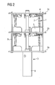
- FIG. 1 a holder for six turbine blades according to the invention is shown in a perspective view, which is designed for use in a coating apparatus.
- the holder has six clamping devices 1, wherein in each case three clamping devices are mounted on a plane via star-shaped holding elements 2 on a linkage 3 of the holder. In each case two clamping devices 1 of the various levels are arranged one above the other with the same orientation in alignment.
- the clamping devices 1 each have a lower, not shown in the drawing clamping element for fixing a blade root and an upper clamping element 4 for fixing a blade of a turbine blade, which are each attached to two superposed holding elements 2. Furthermore, the clamping devices 1 are each provided with a box-shaped masking element 5 for the blade root of the turbine blade.
- the masking element 5 has an open top 6 and an open bottom, wherein the top 6 is formed to enclose a performed airfoil. At the open bottom, a closure flap, not shown in the drawing, can be attached, which closes the masking element 5 after insertion of the turbine blade, so that the blade root of the turbine blade is completely enclosed by the masking element 5.
- the linkage 3 of the holder is formed by a column-shaped central element 8, the holding elements 2 and stiffening rods 9, which connect the superposed holding elements 2 together.
- the central element 8 of the linkage 3 is designed so that it can be rotated automatically about its own axis, for example, after connection with a suitable motor.
- the entire rod 3 is designed to be dismantled.
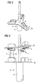
- the middle holding element 2b is pushed onto the central element 8 of the holder until the upper clamping elements 4 formed on the underside of the holding element 2b surround the tips of the blades of the turbine blade 10.
- the shutdown elements 7 cover the trailing edges of the blades.
- the blades are fixed by means of the upper clamping elements 4.
- the holder is shown in this state, but only a turbine blade 10 is fixed.
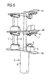
- FIG. 5 shows the holder with an inserted turbine blade 10 with all three retaining elements 2a, 2b, 2c, but without the stiffening rods.
- the bracket may be used with the turbine blade 10 in a coating apparatus.
Landscapes
- Chemical & Material Sciences (AREA)
- Chemical Kinetics & Catalysis (AREA)
- Engineering & Computer Science (AREA)
- Materials Engineering (AREA)
- Mechanical Engineering (AREA)
- Metallurgy (AREA)
- Organic Chemistry (AREA)
- Turbine Rotor Nozzle Sealing (AREA)
Claims (6)
- Fixation pour au moins deux aubes ( 10 ) de turbine à utiliser dans un dispositif de revêtement, qui a, pour chaque aube ( 10 ) de turbine, un dispositif ( 1 ) de blocage pour immobiliser l'emplanture de l'aube et la lame de l'aube, dans lequel au moins deux dispositifs ( 1 ) de blocage sont mis l'un au-dessus de l'autre sur une tringlerie ( 3 ) de la fixation,
caractérisée en ce que
les dispositifs ( 1 ) de blocage ont respectivement un élément inférieur de blocage pour immobiliser une emplanture d'aube et un élément ( 4 ) supérieur de blocage pour immobiliser une lame d'aube d'une aube de turbine,
dans laquelle ceux-ci sont fixés respectivement à deux éléments ( 2 ) de maintien superposés sur la tringlerie ( 3 ), et
dans laquelle respectivement deux dispositifs ( 1 ) de blocage superposés sont superposés en alignement et en ayant la même orientation. - Fixation suivant la revendication 1,
caractérisée en ce que
les dispositifs ( 1 ) de blocage sont munis respectivement d'un élément ( 6 ) de masquage qui entoure l'emplanture de l'aube à l'état bloqué. - Fixation suivant l'une des revendications précédentes,
caractérisée en ce que
les dispositifs ( 1 ) de blocage ont respectivement un élément ( 7 ) de protection pour les bords de fuite de la lame de l'aube. - Fixation suivant l'une des revendications précédentes,
caractérisée en ce que
la tringlerie ( 3 ) a un élément ( 8 ) central par lequel la fixation peut tourner en son entier. - Fixation suivant l'unes des revendications précédentes,
caractérisée en ce que
respectivement trois dispositifs ( 1 ) de blocage sont mis sur la tringlerie ( 3 ) dans deux plans en étant superposés, notamment en étoile. - Fixation suivant l'une des revendications précédentes,
caractérisée en ce que
la tringlerie ( 3 ) peut être désassemblée.
Priority Applications (2)
| Application Number | Priority Date | Filing Date | Title |
|---|---|---|---|
| EP20070013720 EP2014377B1 (fr) | 2007-07-12 | 2007-07-12 | Fixation pour palettes de turbines |
| DE200750003308 DE502007003308D1 (de) | 2007-07-12 | 2007-07-12 | Halterung für Turbinenschaufeln |
Applications Claiming Priority (1)
| Application Number | Priority Date | Filing Date | Title |
|---|---|---|---|
| EP20070013720 EP2014377B1 (fr) | 2007-07-12 | 2007-07-12 | Fixation pour palettes de turbines |
Publications (2)
| Publication Number | Publication Date |
|---|---|
| EP2014377A1 EP2014377A1 (fr) | 2009-01-14 |
| EP2014377B1 true EP2014377B1 (fr) | 2010-03-31 |
Family
ID=38611057
Family Applications (1)
| Application Number | Title | Priority Date | Filing Date |
|---|---|---|---|
| EP20070013720 Not-in-force EP2014377B1 (fr) | 2007-07-12 | 2007-07-12 | Fixation pour palettes de turbines |
Country Status (2)
| Country | Link |
|---|---|
| EP (1) | EP2014377B1 (fr) |
| DE (1) | DE502007003308D1 (fr) |
Cited By (1)
| Publication number | Priority date | Publication date | Assignee | Title |
|---|---|---|---|---|
| CN109397143A (zh) * | 2018-12-13 | 2019-03-01 | 株洲市超宇实业有限责任公司 | 槽刀片涂层夹具 |
Families Citing this family (3)
| Publication number | Priority date | Publication date | Assignee | Title |
|---|---|---|---|---|
| WO2013086286A2 (fr) * | 2011-12-08 | 2013-06-13 | Prexair S. T. Technology, Inc. | Ensemble accessoire d'usinage pour une opération de revêtement |
| DE102014205426A1 (de) * | 2014-03-24 | 2015-09-24 | Siemens Aktiengesellschaft | Gestell zur Halterung von Bauteilen |
| CN116180021A (zh) * | 2022-11-16 | 2023-05-30 | 国营川西机器厂 | 用于航空发动机叶片真空电弧离子镀膜的支撑保护装置 |
Family Cites Families (7)
| Publication number | Priority date | Publication date | Assignee | Title |
|---|---|---|---|---|
| US2645611A (en) * | 1948-09-20 | 1953-07-14 | Shwayder Bros Inc | Method of and bath for electrolytic polishing |
| US3783007A (en) * | 1971-10-01 | 1974-01-01 | Texas Instruments Inc | Metal carbonitrile coatings |
| US4271005A (en) * | 1979-12-03 | 1981-06-02 | United Technologies Corporation | Workpiece support apparatus for use with cathode sputtering devices |
| US5264245A (en) * | 1991-12-04 | 1993-11-23 | Howmet Corporation | CVD method for forming uniform coatings |
| US5803971A (en) * | 1997-01-13 | 1998-09-08 | United Technologies Corporation | Modular coating fixture |
| US6083322A (en) * | 1997-03-06 | 2000-07-04 | United Technologies Corporation | Modular coating fixture |
| DE10258560A1 (de) * | 2002-12-14 | 2004-07-08 | Mtu Aero Engines Gmbh | Verfahren und Vorrichtung zum CVD-Beschichten von Werkstücken |
-
2007
- 2007-07-12 DE DE200750003308 patent/DE502007003308D1/de active Active
- 2007-07-12 EP EP20070013720 patent/EP2014377B1/fr not_active Not-in-force
Cited By (1)
| Publication number | Priority date | Publication date | Assignee | Title |
|---|---|---|---|---|
| CN109397143A (zh) * | 2018-12-13 | 2019-03-01 | 株洲市超宇实业有限责任公司 | 槽刀片涂层夹具 |
Also Published As
| Publication number | Publication date |
|---|---|
| EP2014377A1 (fr) | 2009-01-14 |
| DE502007003308D1 (de) | 2010-05-12 |
Similar Documents
| Publication | Publication Date | Title |
|---|---|---|
| EP2180180B1 (fr) | Aube d'une éolienne avec des trous débouchants de manutention | |
| DE69737037T2 (de) | Modulare befestigung für zu beschichtende werkstücke | |
| EP2014377B1 (fr) | Fixation pour palettes de turbines | |
| DE3110318C2 (fr) | ||
| DE69311676T2 (de) | Verfahren zum Schweissen von beschaufelte Rotorscheiben mit einem Energiestrahl hoher Leistungsdichte | |
| DE1500949B1 (de) | Einbauvorrichtung fuer Duebel in Leichtbau-Schichtverbundplatten | |
| DE112018005864T5 (de) | Vorrichtung und verfahren zur herstellung von zahnprothesen | |
| EP2878812B1 (fr) | Pale de rotor d'éolienne pour un rotor avec cône | |
| EP2268902A1 (fr) | Entretoise pour carter intermédiaire de turbine, carter intermédiaire de turbine, et procédé de production d'un carter intermédiaire de turbine | |
| EP1762303A1 (fr) | Procédé pour préparer des aubes de turbine en vue de leur revêtement par pulvérisation et support pour fixer de telles aubes | |
| EP2659023B1 (fr) | Support pour l'application de revêtements sur des pointes de forets | |
| DE102013211702A1 (de) | Vorrichtung zur Positionierung mehrerer Funktionselemente | |
| DE1905494C3 (de) | Verfahren und Vorrichtung zur Her Stellung einer Unruhspiralfeder | |
| EP1396645A1 (fr) | Dispositif d'assemblage sous un angle de rails de montage | |
| DE102007056690A1 (de) | Anlage zur Herstellung einer Leichtbaustruktur | |
| DE202010000513U1 (de) | Haarersatz mit integrierter Sicherungseinrichtung | |
| DE69200590T2 (de) | Einzelner wendbarer Halter zur Behandlung eines Substrats, insbesondere eines Brillenglases, sowie Anlage zur Anwendung eines solchen Halters. | |
| DE1940722A1 (de) | Rotor fuer Duennschichtbehandlungsapparat | |
| DE2300104C3 (de) | Maschendrahtzaun | |
| DE2643923C2 (de) | Halterung für die Antriebseinheit eines Rolladens | |
| DE202013009757U1 (de) | Insektenschutzdrehtür | |
| DE2307405C3 (de) | Gasheizgerät | |
| DE102019132106B4 (de) | Verschraubungsvorrichtung zur mechanischen Verbindung einer vorderen Trommel und einer hinteren Trommel eines Verdichters eines Gasturbinentriebwerks | |
| DE102018004738A1 (de) | Vorrichtung zum Spannen eines zweiteiligen Nockenwellenrades | |
| DE8901940U1 (de) | Flugkörper mit Leitwerksflossen |
Legal Events
| Date | Code | Title | Description |
|---|---|---|---|
| PUAI | Public reference made under article 153(3) epc to a published international application that has entered the european phase |
Free format text: ORIGINAL CODE: 0009012 |
|
| AK | Designated contracting states |
Kind code of ref document: A1 Designated state(s): AT BE BG CH CY CZ DE DK EE ES FI FR GB GR HU IE IS IT LI LT LU LV MC MT NL PL PT RO SE SI SK TR |
|
| AX | Request for extension of the european patent |
Extension state: AL BA HR MK RS |
|
| 17P | Request for examination filed |
Effective date: 20090223 |
|
| 17Q | First examination report despatched |
Effective date: 20090401 |
|
| AKX | Designation fees paid |
Designated state(s): CH DE FR GB IT LI NL |
|
| GRAP | Despatch of communication of intention to grant a patent |
Free format text: ORIGINAL CODE: EPIDOSNIGR1 |
|
| GRAS | Grant fee paid |
Free format text: ORIGINAL CODE: EPIDOSNIGR3 |
|
| GRAA | (expected) grant |
Free format text: ORIGINAL CODE: 0009210 |
|
| AK | Designated contracting states |
Kind code of ref document: B1 Designated state(s): CH DE FR GB IT LI NL |
|
| REG | Reference to a national code |
Ref country code: CH Ref legal event code: EP Ref country code: GB Ref legal event code: FG4D Free format text: NOT ENGLISH |
|
| REG | Reference to a national code |
Ref country code: CH Ref legal event code: NV Representative=s name: SIEMENS SCHWEIZ AG |
|
| REF | Corresponds to: |
Ref document number: 502007003308 Country of ref document: DE Date of ref document: 20100512 Kind code of ref document: P |
|
| REG | Reference to a national code |
Ref country code: NL Ref legal event code: VDEP Effective date: 20100331 |
|
| PG25 | Lapsed in a contracting state [announced via postgrant information from national office to epo] |
Ref country code: NL Free format text: LAPSE BECAUSE OF FAILURE TO SUBMIT A TRANSLATION OF THE DESCRIPTION OR TO PAY THE FEE WITHIN THE PRESCRIBED TIME-LIMIT Effective date: 20100331 |
|
| PLBE | No opposition filed within time limit |
Free format text: ORIGINAL CODE: 0009261 |
|
| STAA | Information on the status of an ep patent application or granted ep patent |
Free format text: STATUS: NO OPPOSITION FILED WITHIN TIME LIMIT |
|
| 26N | No opposition filed |
Effective date: 20110104 |
|
| PG25 | Lapsed in a contracting state [announced via postgrant information from national office to epo] |
Ref country code: IT Free format text: LAPSE BECAUSE OF FAILURE TO SUBMIT A TRANSLATION OF THE DESCRIPTION OR TO PAY THE FEE WITHIN THE PRESCRIBED TIME-LIMIT Effective date: 20100331 |
|
| REG | Reference to a national code |
Ref country code: FR Ref legal event code: ST Effective date: 20110331 |
|
| PG25 | Lapsed in a contracting state [announced via postgrant information from national office to epo] |
Ref country code: FR Free format text: LAPSE BECAUSE OF NON-PAYMENT OF DUE FEES Effective date: 20100802 |
|
| PGFP | Annual fee paid to national office [announced via postgrant information from national office to epo] |
Ref country code: GB Payment date: 20120709 Year of fee payment: 6 |
|
| PGFP | Annual fee paid to national office [announced via postgrant information from national office to epo] |
Ref country code: DE Payment date: 20120906 Year of fee payment: 6 |
|
| PGFP | Annual fee paid to national office [announced via postgrant information from national office to epo] |
Ref country code: CH Payment date: 20121011 Year of fee payment: 6 |
|
| REG | Reference to a national code |
Ref country code: CH Ref legal event code: PL |
|
| GBPC | Gb: european patent ceased through non-payment of renewal fee |
Effective date: 20130712 |
|
| REG | Reference to a national code |
Ref country code: DE Ref legal event code: R119 Ref document number: 502007003308 Country of ref document: DE Effective date: 20140201 |
|
| PG25 | Lapsed in a contracting state [announced via postgrant information from national office to epo] |
Ref country code: CH Free format text: LAPSE BECAUSE OF NON-PAYMENT OF DUE FEES Effective date: 20130731 Ref country code: DE Free format text: LAPSE BECAUSE OF NON-PAYMENT OF DUE FEES Effective date: 20140201 Ref country code: GB Free format text: LAPSE BECAUSE OF NON-PAYMENT OF DUE FEES Effective date: 20130712 Ref country code: LI Free format text: LAPSE BECAUSE OF NON-PAYMENT OF DUE FEES Effective date: 20130731 |