EP2014477B1 - Thermischer Drucker - Google Patents
Thermischer Drucker Download PDFInfo
- Publication number
- EP2014477B1 EP2014477B1 EP08075801A EP08075801A EP2014477B1 EP 2014477 B1 EP2014477 B1 EP 2014477B1 EP 08075801 A EP08075801 A EP 08075801A EP 08075801 A EP08075801 A EP 08075801A EP 2014477 B1 EP2014477 B1 EP 2014477B1
- Authority
- EP
- European Patent Office
- Prior art keywords
- platen
- lock
- thermal activation
- platen roller
- sheet material
- Prior art date
- Legal status (The legal status is an assumption and is not a legal conclusion. Google has not performed a legal analysis and makes no representation as to the accuracy of the status listed.)
- Expired - Lifetime
Links
- 238000007725 thermal activation Methods 0.000 claims description 73
- 239000000463 material Substances 0.000 claims description 64
- 238000007639 printing Methods 0.000 claims description 33
- 238000010438 heat treatment Methods 0.000 claims description 20
- 230000006835 compression Effects 0.000 claims description 16
- 238000007906 compression Methods 0.000 claims description 16
- 239000012790 adhesive layer Substances 0.000 claims description 15
- 230000008878 coupling Effects 0.000 claims description 7
- 238000010168 coupling process Methods 0.000 claims description 7
- 238000005859 coupling reaction Methods 0.000 claims description 7
- 230000003213 activating effect Effects 0.000 claims description 5
- 230000005855 radiation Effects 0.000 claims 1
- 239000010410 layer Substances 0.000 description 13
- 238000010276 construction Methods 0.000 description 8
- 230000002093 peripheral effect Effects 0.000 description 7
- 238000007651 thermal printing Methods 0.000 description 6
- 230000002401 inhibitory effect Effects 0.000 description 2
- 238000012423 maintenance Methods 0.000 description 2
- 238000007599 discharging Methods 0.000 description 1
Images






Classifications
-
- B—PERFORMING OPERATIONS; TRANSPORTING
- B41—PRINTING; LINING MACHINES; TYPEWRITERS; STAMPS
- B41J—TYPEWRITERS; SELECTIVE PRINTING MECHANISMS, i.e. MECHANISMS PRINTING OTHERWISE THAN FROM A FORME; CORRECTION OF TYPOGRAPHICAL ERRORS
- B41J11/00—Devices or arrangements of selective printing mechanisms, e.g. ink-jet printers or thermal printers, for supporting or handling copy material in sheet or web form
- B41J11/24—Detents, brakes, or couplings for feed rollers or platens
-
- B—PERFORMING OPERATIONS; TRANSPORTING
- B41—PRINTING; LINING MACHINES; TYPEWRITERS; STAMPS
- B41J—TYPEWRITERS; SELECTIVE PRINTING MECHANISMS, i.e. MECHANISMS PRINTING OTHERWISE THAN FROM A FORME; CORRECTION OF TYPOGRAPHICAL ERRORS
- B41J11/00—Devices or arrangements of selective printing mechanisms, e.g. ink-jet printers or thermal printers, for supporting or handling copy material in sheet or web form
- B41J11/02—Platens
- B41J11/04—Roller platens
-
- B—PERFORMING OPERATIONS; TRANSPORTING
- B41—PRINTING; LINING MACHINES; TYPEWRITERS; STAMPS
- B41J—TYPEWRITERS; SELECTIVE PRINTING MECHANISMS, i.e. MECHANISMS PRINTING OTHERWISE THAN FROM A FORME; CORRECTION OF TYPOGRAPHICAL ERRORS
- B41J2/00—Typewriters or selective printing mechanisms characterised by the printing or marking process for which they are designed
- B41J2/315—Typewriters or selective printing mechanisms characterised by the printing or marking process for which they are designed characterised by selective application of heat to a heat sensitive printing or impression-transfer material
- B41J2/32—Typewriters or selective printing mechanisms characterised by the printing or marking process for which they are designed characterised by selective application of heat to a heat sensitive printing or impression-transfer material using thermal heads
Definitions
- the present invention relates to a thermal activation device for thermally activating a heat-sensitive adhesive layer of a sheet material having a printing layer formed on one surface of a sheet-like base material and having the heat-sensitive adhesive layer formed on the other surface, and relates to a printer for performing printing on the sheet material in which the printing layer is provided on the one surface of the sheet-like base material.
- labels for displaying various types of information such as prices and for displaying barcodes for management by means of POS (point of sales) terminals have been used by being attached to articles.
- POS point of sales
- a label issuing instrument which issues the label having the heat-sensitive adhesive layer as described above includes a sheet supply apparatus that supplies the sheet material, a printing apparatus that prints various types of information on a thermal printing layer of the sheet material supplied from the sheet supply apparatus, a cutting apparatus that cuts the sheet material for which the printing has been performed by the printing apparatus, and a thermal activation device that thermally activates the heat-sensitive adhesive layer of the sheet material.
- each of the apparatuses has a platen roller for conveying the sheet material, with the thermal head and the thermal activation head being brought into press contact with the platen roller.
- a so-called clamshell-type construction has been adopted, which includes a platen unit that is movable so as to bring the platen roller into and out of contact with the thermal head or the thermal activation head, and exposes the thermal head and the thermal activation head to the outside of the apparatus, thus facilitating exchange, maintenance, etc. of the heads.
- a construction has also been adopted, in which the thermal head and the thermal activation head are movable so as to come into and out of contact with the platen roller.
- each of the conventional clamshell-type printing apparatus and thermal activation device includes a platen lock mechanism for locking the platen unit so as to fix movement thereof in a state where the thermal head or the thermal activation head is brought into press contact with the platen roller.
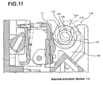
- a conventional thermal activation device 110 includes aplaten lockmechanism 119 for locking a thermal activation head 111 into press contact with a platen roller 112.
- the platen lock mechanism 119 has a lock arm 132 provided so as to be rotatable.
- an engagement groove 137 which is engaged with an outer peripheral portion of a bearing 126 that holds a rotary shaft 125 of the platen roller 112 so as to be freely rotatable, is formed by being notched.
- the platen lock mechanism 119 operates to rotate the lock arm 132.
- an engaged state of the bearing 126 of the platen roller 112 and the lock arm 132 is released, and a platen unit (not shown) which supports the platen roller 112 is rotationally driven in a direction of an arrow c 2 , and the platen roller 112 is moved to a position spaced apart from the thermal activation head 111.
- the platen unit (not shown) which supports the platen roller 112 is rotationally driven in a direction of an arrow c 1 , the platen roller 112 is moved into press contact with the thermal activation head 111, and the bearing 126 of the platen roller 112 and the engagement groove 137 of the lock arm 132 are engaged with each other.
- the platen lock mechanism provided in the conventional clamshell-type printing apparatus or thermal activation device has the lock arm engaged with the rotary shaft of the platen roller or the outer peripheral portion of the bearing thereof.
- an operation range of the rotating lock arm is relatively large, and a conveyor roller is placed at a position not inhibiting the movement of the lock arm.
- a distance between the conveyor roller and the platen roller cannot be shortened. Accordingly, it has been difficult to achieve miniaturization of the entire apparatus.
- the operation range of the lock arm is relatively large, and accordingly, in the case of using a compression coil spring which urges the lock arm, it is necessary to ensure relatively large compression for the compression coil spring. This leads to enlargement of the compression coil spring, and thus it has been difficult to miniaturize the entire apparatus.
- thermo activation device and a printer which are capable of achieving miniaturization of the entire apparatus and of conveying a sheet material having a relatively short length in the conveying direction.
- a thermal activation device includes: heating means for thermally activating a heat-sensitive adhesive layer of a sheet material having the heat-sensitive adhesive layer; a platen unit that includes a platen roller for conveying the sheet material, the platen roller being brought into press contact with the heating means, the platen unit being movable in a direction for bringing the platen roller into and out of contact with the heating means; and a platen lock mechanism for locking the platen roller and the heating means into press contact with each other, the platen lock mechanism including a lock arm that is rotatable and engaged with the platen unit, and urging means for urging the lock arm in a direction for bringing the lock arm into engagement with the platen roller.
- the platen lock mechanism includes a shaft member provided in one of the platen unit and the lock arm, and an engagement recess which is provided in the other and with which the shaft member is engaged. Further, in the platen lock mechanism, an axis of the shaft member is provided at a position farther than a position of a rotation center of the platen roller with respect to a rotation center of the lock arm, with the printing means being in press contact with the platen roller.
- the thermal activation device of the present invention which is constructed as described above, as the shaft member is separating from the rotation center of the lock arm, the operation range of the lock arm when the lock arm shifts between a locking state and an unlocking state is reduced. Accordingly, it is possible to reduce the requisite urging force by the urging means, and the urging means is miniaturized, thus making it possible to achieve the miniaturization of the entire apparatus. Moreover, according to the thermal activation device of the present invention, it is possible to place the shaft member at a position spaced apart from the vicinity of the platen roller, where relatively many components are placed, and it is possible to handle conveyance of a sheet material having a short length in the conveying direction.
- an outer diameter of the shaft member is smaller than one of an outer diameter of a rotary shaft of the platen roller and an outer diameter of a bearing that supports the rotary shaft.
- a thermal activation device includes: heating means for thermally activating a heat-sensitive adhesive layer of a sheet material having the heat-sensitive adhesive layer; a platen unit that includes a platen roller for conveying the sheet material, the platen roller being brought into press contact with the heating means, the platen unit being movable in a direction for bringing the platen roller into and out of contact with the heating means; and a platen lock mechanism for locking the platen roller and the heating means into press contact with each other, the platen lock mechanism including a lock arm that is rotatable and engaged with the platen unit, and urging means for urging the lock arm in a direction for bringing the lock arm into engagement with the platen roller.
- the platen lock mechanism includes a shaft member provided in one of the platen unit and the lock arm, and an engagement recess which is provided in the other and with which the shaft member is engaged. Further, an outer diameter of the shaft member is smaller than one of an outer diameter of a rotary shaft of the platen roller and an outer diameter of a bearing that supports the rotary shaft.
- the thermal activation device may include a pair of conveyor rollers for conveying the sheet material to the heating means side.
- the operation range of the lock arm is reduced, and accordingly, it is possible to place the conveyor rollers close to the platen roller side without inhibiting the rotation of the lock arm, and the overall miniaturization of the apparatus can be achieved.
- the thermal activation device the shortest sheet material length which the apparatus can handle can be further shortened.
- the platen lock mechanism equipped to the thermal activation device is also applicable to a printer that includes: printing means for performing printing on a sheet material; and a platen unit that includes a platen roller for conveying the sheet material, the platen roller being brought into press contact with the printing means, the platen unit being movable in a direction for bringing the platen roller into and out of contact with the printing means.
- the thermal activation device and the printer in accordance with the present invention each includes the platen lock mechanism including the shaft member provided in one of the platen unit and the lock arm, and the engagement recess provided in the other with which the shaft member is engaged.
- the axis of the shaft member is provided at the position farther than the position of the rotation center of the platen roller with respect to the rotation position of the lock arm, or alternatively, the outer diameter of the shaft member is set smaller than the outer diameter of the rotary shaft of the platen roller or the outer diameter of the bearing which supports the rotary shaft, whereby the miniaturization of the entire apparatus can be achieved.
- a label issuing instrument 1 includes a printing apparatus 6 that prints various types of information on a thermal printing layer of a sheet material 3 which is supplied from a sheet roll 5 around which the sheet material 3 is wound, a cutting apparatus 7 that cuts the sheet material 3 for which the printing has been performed by the printing apparatus 6, and a thermal activation device 10 that thermally activates a heat-sensitive adhesive layer of the sheet material 3, which are provided in the stated order along a conveyor route of the sheet material 3 in the direction indicated by an arrow L in FIG. 1 .
- the sheet material 3 includes a sheet-like base material, the thermal printing layer formed on a surface side of the sheet-like base material, and the heat-sensitive adhesive layer provided on a back surface side of the sheet-like base material.
- the sheet material one having a construction in which a heat-insulating layer for shielding heat conduction from one-side layer of the sheet-like base material to the other-side layer thereof is provided between the sheet-like base material and the thermal printing layer.
- a so-called thermal printer is used as the printing apparatus 6, and the printing apparatus 6 includes a thermal head 6a for making the thermal printing layer of the sheet material 3 heat-sensitive, and a platen roller 6b brought into press contact with the thermal head 6a. While sandwiching the sheet material 3 supplied from the sheet supply apparatus 5 between the thermal head 6a and the platen roller 6b, the printing apparatus 6 performs printing for the sheet material 3, and conveys the sheet material 3. Note that the printing apparatus 6 may be disposed on a downstream side of the thermal activation device 10 in the conveying direction of the sheet material 3 according to needs.
- the cutting apparatus 7 includes a cutter 7a for cutting the sheet material 3 discharged from the printing apparatus 6 into a desired length, and conveys the sheet material 3 thus cut to the thermal activation device 10.
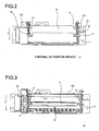
- the thermal activation device 10 includes a thermal activation head 11 for thermally activating the heat-sensitive adhesive layer of the sheet material 3, a platen roller 12 which is brought into press contact with the thermal activation head 11 and conveys the sheet material 3 in the conveying direction as the direction indicated by the arrow L while sandwiching the sheet material 3 between the platen roller 12 itself and the thermal activation head 11, a pair of feed-in rollers 13a and 13b for feeding the sheet material 3 conveyed from the cutting apparatus 7 into the thermal activation device 10, and a pair of discharge rollers 15a and 15b for discharging the sheet material 3 thermally activated by the thermal activation head 11 to the outside of the thermal activation device 10.
- the thermal activation device 10 includes base frames 17 each of which supports the thermal activation head 11, a platen unit 18 which supports the platen roller 12, and a platen lock mechanism 19 which locks the platen unit 18 into a state where the platen roller 12 is in press contact with the thermal activation head 11.
- thermal activation head 11 one similar to the thermal head 6a provided to the printing apparatus 6 is used, and plural heating elements (not shown) are placed along the width direction perpendicular to the conveying direction of the sheet material 3.
- the thermal activation head 11 selectively heats arbitrary heating elements, thus making it possible to thermally activate the heat-sensitive adhesive layer per dot unit in the width direction of the sheet material 3.
- the thermal activation head 11 is provided on a radiator 21, and the radiator 21 is supported by a rotary support member 22.
- the rotary support member 22 one end thereof is supported by a rotation support shaft 23 so as to be rotatable, and the other end is urged with an elastic force of a compression coil spring 24.
- the rotary support member 22 is rotated about the rotation support shaft 23 in directions of arrows a 1 and a 2 by the urging force from the compression coil spring 24, and the thermal activation head 11 is brought into press contact with the peripheral surface of the platen roller 12.
- the platen roller 12 is supported by a rotary shaft 25, and both ends of the rotary shaft 25 are supported on a bearing 26 so as to be rotatable. As shown in FIG. 3 , the platen roller 12 is rotationally driven by a drive mechanism 29 having a gear array. As one of the conveyor rollers 13a and 13b is rotationally driven, the other is rotationally driven following the rotation of the one conveyor roller.
- the base frames 17 are arranged on both sides in the width direction of the sheet material 3, and on the base frames 17, the rotary support member 22 for the thermal activation head 11, the conveyor roller 13b, and the discharge roller 15 are supported so as to be rotatable.
- the platen unit 18 includes sub-frames 27 arranged on both sides in the width direction of the sheet material 3, and the sub-frames 27 are supported on the base frames 17 through a rotary shaft 28 so as to be rotatable in directions of arrows b 1 and b 2 .
- the platen unit 18 is movable so as to allow the peripheral surface of the platen roller 12 into and out of contact with the thermal activation head 11 by rotating in the directions of the arrows b 1 and b 2 .
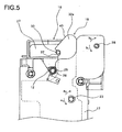
- the platen lock mechanism 19 includes a lock member 31 having a pair of lock arms 32a and 32b engaged with the platen unit 18, and lock pins 33 which are shaft members with which the lock arms 32 are engaged.
- the lock member 31 is formed by integrally coupling the pair of lock arms 32a and 32b, which are individually engaged with the respective lock pins 33, through the intermediation of a coupling piece 35.
- the lock member 31 is supported on the rotation support shaft 23 which functions as the rotation center of the rotary support member 22 supporting the thermal activation head 11 so as to be rotatable in the directions of the arrows a 1 and a 2 .
- the respective lock arms 32a and 32b are notched to form engagement grooves 37 that are engagement recesses with which the respective lock pins 33 are engaged.
- the engagement grooves 37 are formed into a substantially circular arc shape corresponding to the outer diameter of the lock pins 33.
- operation portion 40 for rotating the lock member 31 in the direction of the arrow a 2 through a pressing operation by means of the lock pins 33 are formed into a substantially linear shape.
- an operation lever 38 is provided integrally therewith.
- the coupling piece 35 is integrally provided with a spring support piece 39 that is urged with the elastic force of the above-described compression coil spring 24 bringing the thermal activation head 11 into press contact with the platen roller 12.
- a protruding portion 39a engaged with a center hole of the compression coil spring 24 is provided.
- the lock arms 32a and 32b of the lock member 31 are urged by the elastic force of the compression coil spring 24 so as to rotate about the rotation support shaft 23 in the direction of the arrow a 1 in a way similar to the thermal activation head 11, and the engagement grooves 37 of the respective lock arms 32a and 32b are engaged with the lock pins 33.
- the lock pins 33 are fixed to the respective sub-frames 27 of the platen unit 18 so as to be in parallel to the rotary shaft 25 of the platen roller 12.
- the outer diameter of the lock pins 33 is set to be smaller than the outer diameter of the bearing 26 of the platen roller 12 and the outer diameter of the rotary shaft 25 thereof.
- the axis of the lock pins 33 is at a position farther from the rotation support shaft 23, which is the rotation center of the lock arms 32a and 32b, than the rotary shaft 25 of the platen roller 12.
- a distance e between the axis of the rotation support shaft 23 which functions as the rotation center of the lock arms 32a and 32b and the axis of the lock pins 33 is set larger than a distance d between the axis of the rotation support shaft 23 of the lock arms 32a and 32b and the axis of the rotary shaft 25 of the platen roller 12.
- the lock arms 32a and 32b are engaged with the lock pins 33 provided at the positions as described above. In this way, an operation range of the lock arms 32a and 32b about the rotary shaft 23, that is, the movement of the engagement grooves 37 when the lock arms 32a and 32b shift between a locking state and an unlocking state can be made smaller than in the case where the lock arms 32a and 32b are engaged with the outer peripheral portions of the rotary shaft 25 and bearing 26 of the platen roller 26.
- the reduced operation range of the lock arms 32a and 32b makes it possible to arrange the conveyor rollers 13a and 13b in close proximity to the platen roller 12 without making the conveyor rollers 13a and 13b interfere with the rotating lock arms 32a and 32b.
- the above-mentioned platen lock mechanism 19 is constructed such that the lock pins 33 are provided on the platen unit 18 side, and that the engagement grooves 37 with which the lock pins 33 are engaged are formed on the lock arms 32a and 32b side.
- any construction may be employed as long as the lock pins 33 are located farther than the rotation center of the platen roller 12 with respect to the rotation center of the lock arms 32a and 32b.
- a construction may also be adopted in which the lock pins 33 are provided on the lock arms 32a and 32b side, and the engagement grooves are formed on the sub-frames 27 on the platen unit 18 side.
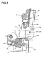
- the platen lock mechanism 19 the engaged state of the engagement grooves 37 of the lock arms 32a and 32b with the lock pins 33 is released, and thus the platen unit 18 is rotated in the direction of the arrow b 2 with respect to the base frames 17 so as to open.
- work such as exchange and maintenance of the thermal activation head 11 is performed in this state, and good workability is thus maintained.
- the platen unit 18 is rotated in the direction of the arrow b 1 with respect to the base frames 17, and the lock pins 33 are thus made to abut on the operation portions 40 of the lock arms 32a and 32b.
- the lock pins 33 are moved along the operation portions 40, and the lock arms 32a and 32b are rotated in the direction of the arrow a 2 by the lock pins 33 against the urging force of the compression coil spring 24.
- the operation lever 38 provided in the lock arm 32 that is one of the lock arms is operated so as to rotate in the direction of the arrow a 2 against the urging force by the compression coil spring 24, and the engaged state of the engagement grooves 37 of the respective lock arms 32a and 32b with the respective lock pins 33 is thus released, thus making it possible to operate the platen unit 18 so as to rotate in the direction of the arrow b 2 with respect to the sub-frames 27.
- the platen lock mechanism 19 includes the lock pins 33 provided at the position farther than the rotary shaft 25 constituting the rotation center of the platen roller 12 with,respect to the rotation support shaft 23 constituting the rotation center of the lock arms 32a and 32b.
- the operation range of the lock arms 32a and 32b in the case where the lock arms 32a and 32b shift between the locking state and the unlocking state is reduced. Therefore, according to the thermal activation device 10, it is possible to arrange the conveyor rollers 13a and 13b and the discharge roller 15 at positions close to the platen roller 12, and the overall miniaturization of the thermal activation device 10 can be achieved.
- the thermal activation device 10 because it is possible to arrange the conveyor rollers 13a and 13b at positions close to the platen roller 12, it is possible to convey the sheet material 3 such as a cut sheet having a relatively short length in the conveying direction. Furthermore, according to the thermal activation device 10, an amount of deflection, which occurs in the sheet material 3 between an upstream-side holding position by the conveyor rollers 13a and 13b and a downstream-side holding position by the platen roller 12 and the thermal activation head 11, is suppressed.
- Conveying force by the conveyor rollers 13a and 13b is smoothly transmitted to the sheet material 3 owing to the elastic force of the sheet material 3 itself, allowing the sheet material 3 to be smoothly forwarded by the conveyor rollers 13a and 13b, and conveying force by the platen roller 12 is supplemented. As a result, it is possible to restrict the sheet material 3 from inclining with respect to the conveying direction to cause skew feed.
- the platen lock mechanism may also be applied to a printing apparatus provided in a label issuing apparatus.
- the sheet material having the thermal printing layer has been adopted in the thermal activation device of the above-described embodiment, for example, other sheet materials having a pressure-sensitive printing layer and the like may also be used.
Landscapes
- Electronic Switches (AREA)
- Handling Of Sheets (AREA)
Claims (5)
- Wärmeaktivierungsvorrichtung (10), umfassend:ein Heizmittel (11) zum Wärmeaktivieren einer wärmeempfindlichen Klebstoffschicht eines Blattmaterials (3), das die wärmeempfindliche Klebstoffschicht aufweist;eine Walzeneinheit (18), die ein Lager (26) und eine Schreibwalze (12) zum Befördern des Blattmaterials (3) enthält, wobei die Schreibwalze (12) eine Drehwelle (25) aufweist, die von dem Lager (26) gestützt wird, wobei die Schreibwalze (12) mit dem Heizmittel (11) in Presskontakt gebracht wird, wobei die Walzeneinheit (18) in eine Richtung bewegbar ist, um die Schreibwalze (12) in den und aus dem Kontakt mit dem Heizmittel (11) zu bringen; undeinen Walzenverriegelungsmechanismus (19) zum Verriegeln der Schreibwalze (12) und des Heizmittels (11) in Presskontakt miteinander, wobei der Walzenverriegelungsmechanismus (19) Verriegelungsarme (32a, 32b) enthält, die drehbar und mit der Walzeneinheit (18) in Eingriff sind, und Pressmittel (24) zum Pressen der Verriegelungsarme (32a, 32b) in eine Richtung, um die Verriegelungsarme (32a, 32b) mit der Schreibwalze (12) in Eingriff zu bringen,wobei der Walzenverriegelungsmechanismus (19) ein Wellenelement (33) enthält, das in einem von der Walzeneinheit (18) und den Verriegelungsarmen (32a, 32b) bereitgestellt ist, und eine Eingriffsvertiefung (37), die in dem anderen bereitgestellt ist und mit der das Wellenelement (33) in Eingriff steht, und wobei ein Außendurchmesser des Wellenelements (33) kleiner als einer von einem Außendurchmesser der Drehwelle (25) und einem Außendurchmesser des Lagers (26) ist, das die Drehwelle (25) stützt;dadurch gekennzeichnet, dass:der Walzenverriegelungsmechanismus (19) ein Kopplungsstück (35) enthält und durch integrales Koppeln der Verriegelungsarme (32a, 32b) durch das Kopplungsstück (35) gebildet ist;die Wärmeaktivierungsvorrichtung des weiteren ein drehendes Stützelement (22), eine Rotationsstützwelle (23), ein Federstützelement (39), das mit dem Kopplungsstück (35) integral ist, und einen Radiator (21) umfasst;das Heizmittel (11) an dem Radiator (21) bereitgestellt ist, der von dem drehenden Stützelement (22) gestützt wird;die Verriegelungsarme (32a, 32b) und ein Ende des drehenden Stützelements (22) von der Rotationsstützwelle (23) so gestützt werden, dass sie drehbar sind, unddass das Pressmittel (24) eine Druckschraubenfeder ist, die zwischen dem drehenden Stützelement (22) und dem Federstützelement (39) bereitgestellt ist, so dass das Heizmittel (11) mit der Schreibwalze (12) in Presskontakt gebracht wird und das Wellenelement (33) mit der Eingriffsvertiefung (37) in Eingriff gebracht werden kann.
- Wärmeaktivierungsvorrichtung nach Anspruch 10, wobei das Wellenelement (33) in der Walzeneinheit (18) bereitgestellt ist.
- Wärmeaktivierungsvorrichtung nach Anspruch 1, wobei das Heizmittel (11) einen Thermokopf (6a) enthält.
- Wärmeaktivierungsvorrichtung nach Anspruch 1, des Weiteren umfassend ein Paar von Förderwalzen (13a, 13b) zum Befördern des Blattmaterials (3) zu dem Heizmittel (11).
- Drucker, umfassend:ein Druckmittel zum Durchführen eines Drucks auf einem Blattmaterial; unddie Wärmeaktivierungsvorrichtung nach einem der Ansprüche 1 bis 4.
Applications Claiming Priority (2)
| Application Number | Priority Date | Filing Date | Title |
|---|---|---|---|
| JP2004163089A JP2005342942A (ja) | 2004-06-01 | 2004-06-01 | 熱活性化装置およびプリンタ |
| EP05253074A EP1602502B1 (de) | 2004-06-01 | 2005-05-18 | Thermischer Drucker |
Related Parent Applications (2)
| Application Number | Title | Priority Date | Filing Date |
|---|---|---|---|
| EP05253074.8 Division | 2005-05-18 | ||
| EP05253074A Division EP1602502B1 (de) | 2004-06-01 | 2005-05-18 | Thermischer Drucker |
Publications (3)
| Publication Number | Publication Date |
|---|---|
| EP2014477A2 EP2014477A2 (de) | 2009-01-14 |
| EP2014477A3 EP2014477A3 (de) | 2009-04-15 |
| EP2014477B1 true EP2014477B1 (de) | 2010-06-23 |
Family
ID=34979516
Family Applications (2)
| Application Number | Title | Priority Date | Filing Date |
|---|---|---|---|
| EP08075801A Expired - Lifetime EP2014477B1 (de) | 2004-06-01 | 2005-05-18 | Thermischer Drucker |
| EP05253074A Expired - Lifetime EP1602502B1 (de) | 2004-06-01 | 2005-05-18 | Thermischer Drucker |
Family Applications After (1)
| Application Number | Title | Priority Date | Filing Date |
|---|---|---|---|
| EP05253074A Expired - Lifetime EP1602502B1 (de) | 2004-06-01 | 2005-05-18 | Thermischer Drucker |
Country Status (4)
| Country | Link |
|---|---|
| US (1) | US7537402B2 (de) |
| EP (2) | EP2014477B1 (de) |
| JP (1) | JP2005342942A (de) |
| DE (2) | DE602005022959D1 (de) |
Families Citing this family (6)
| Publication number | Priority date | Publication date | Assignee | Title |
|---|---|---|---|---|
| FR2915926B1 (fr) * | 2007-05-09 | 2011-02-11 | A P S Engineering | Dispositif de montage d'un couvercle verrouillable monte mobile sur le chassis d'un mecanisme d'impression thermique |
| JP2011073372A (ja) * | 2009-09-30 | 2011-04-14 | Seiko Instruments Inc | サーマルプリンタ |
| TWI534015B (zh) * | 2010-05-17 | 2016-05-21 | 滿捷特科技公司 | 於印表機中降低墨水混色效應之系統 |
| EP2739478A4 (de) * | 2011-08-04 | 2015-07-29 | Nulabel Technologies Inc | Trägerbandlose etikettendrucker mit etikettkleberaktivierung |
| JP6351502B2 (ja) | 2014-12-24 | 2018-07-04 | セイコーインスツル株式会社 | 印字ユニット及びサーマルプリンタ |
| JP2017205899A (ja) | 2016-05-16 | 2017-11-24 | セイコーインスツル株式会社 | サーマルプリンタ及び携帯型端末 |
Family Cites Families (10)
| Publication number | Priority date | Publication date | Assignee | Title |
|---|---|---|---|---|
| JPH04148749A (ja) * | 1990-10-09 | 1992-05-21 | Matsushita Electric Ind Co Ltd | 画像読取装置 |
| DE4224533A1 (de) * | 1991-07-25 | 1993-01-28 | Kanzaki Paper Mfg Co Ltd | Thermo-drucker |
| JP3491790B2 (ja) * | 1996-01-18 | 2004-01-26 | ブラザー工業株式会社 | 印字装置 |
| JP3623084B2 (ja) * | 1996-10-18 | 2005-02-23 | 株式会社リコー | 感熱性粘着ラベルの熱活性化方法及び感熱性粘着ラベルの貼り付け方法 |
| WO1998043820A1 (en) * | 1997-04-02 | 1998-10-08 | Seiko Epson Corporation | Paper roll loading mechanism for printers |
| JPH1110925A (ja) * | 1997-06-19 | 1999-01-19 | Star Micronics Co Ltd | プリンタ |
| JP2000094767A (ja) * | 1998-09-25 | 2000-04-04 | Fujitsu Takamisawa Component Ltd | サーマルプリンタ |
| EP1108556B1 (de) * | 1999-12-15 | 2003-04-16 | Seiko Epson Corporation | Drucker |
| JP3885564B2 (ja) * | 2001-11-16 | 2007-02-21 | セイコーエプソン株式会社 | プリンタ及びプリンタユニット |
| JP4350350B2 (ja) * | 2002-09-27 | 2009-10-21 | セイコーインスツル株式会社 | サーマルプリンタ |
-
2004
- 2004-06-01 JP JP2004163089A patent/JP2005342942A/ja not_active Withdrawn
-
2005
- 2005-05-18 EP EP08075801A patent/EP2014477B1/de not_active Expired - Lifetime
- 2005-05-18 DE DE602005022959T patent/DE602005022959D1/de not_active Expired - Lifetime
- 2005-05-18 EP EP05253074A patent/EP1602502B1/de not_active Expired - Lifetime
- 2005-05-18 DE DE602005022000T patent/DE602005022000D1/de not_active Expired - Lifetime
- 2005-05-25 US US11/137,846 patent/US7537402B2/en not_active Expired - Fee Related
Also Published As
| Publication number | Publication date |
|---|---|
| EP1602502B1 (de) | 2010-08-18 |
| EP2014477A3 (de) | 2009-04-15 |
| EP2014477A2 (de) | 2009-01-14 |
| JP2005342942A (ja) | 2005-12-15 |
| DE602005022959D1 (de) | 2010-09-30 |
| EP1602502A1 (de) | 2005-12-07 |
| DE602005022000D1 (de) | 2010-08-05 |
| US20050271443A1 (en) | 2005-12-08 |
| US7537402B2 (en) | 2009-05-26 |
Similar Documents
| Publication | Publication Date | Title |
|---|---|---|
| JP5074562B2 (ja) | カッターユニットおよびプリンタ | |
| JP4732774B2 (ja) | プリンタ及びプリント方法 | |
| EP2014477B1 (de) | Thermischer Drucker | |
| EP1808389B1 (de) | Mechanismus zum Zwischenspeichern und Drucker | |
| JP4817101B2 (ja) | 熱活性化装置、印字装置およびプリンタ | |
| US6231251B1 (en) | Printing apparatus with a printhead rotatable between a printing position and a service position | |
| JP4951929B2 (ja) | スリッタ装置及びプリンタ | |
| EP1447227B1 (de) | Thermodrucker | |
| JP4777915B2 (ja) | 熱活性プリンタ | |
| EP1602493B1 (de) | Wärmeaktivierungsgerät | |
| JP5139401B2 (ja) | ラベルプリンタ | |
| JP7629746B2 (ja) | サーマルプリンタ | |
| JP2011251346A (ja) | カッタ及びプリンタ | |
| JP4498080B2 (ja) | プリンタ | |
| JP5704999B2 (ja) | サーマルプリンタ装置 | |
| JP3686632B2 (ja) | プリンタ | |
| JP7638122B2 (ja) | サーマルプリンタ | |
| JP4959834B2 (ja) | プリンタ及びプリント方法 | |
| JP2013166264A (ja) | カッター装置、粘着ラベル発行装置、及びプリンタ | |
| JP6381104B2 (ja) | プリンタ | |
| JP2004261915A (ja) | カッター及びプリンタ | |
| JP2003118151A (ja) | サーマルプリンタ | |
| JP2008023859A (ja) | ラベル発行装置 | |
| JP2003025658A (ja) | プリンタ | |
| JPH082047A (ja) | プリンタ装置 |
Legal Events
| Date | Code | Title | Description |
|---|---|---|---|
| PUAI | Public reference made under article 153(3) epc to a published international application that has entered the european phase |
Free format text: ORIGINAL CODE: 0009012 |
|
| PUAI | Public reference made under article 153(3) epc to a published international application that has entered the european phase |
Free format text: ORIGINAL CODE: 0009012 |
|
| 17P | Request for examination filed |
Effective date: 20081024 |
|
| AC | Divisional application: reference to earlier application |
Ref document number: 1602502 Country of ref document: EP Kind code of ref document: P |
|
| AK | Designated contracting states |
Kind code of ref document: A2 Designated state(s): DE FR IT |
|
| PUAL | Search report despatched |
Free format text: ORIGINAL CODE: 0009013 |
|
| AK | Designated contracting states |
Kind code of ref document: A3 Designated state(s): DE FR IT |
|
| GRAP | Despatch of communication of intention to grant a patent |
Free format text: ORIGINAL CODE: EPIDOSNIGR1 |
|
| AKX | Designation fees paid |
Designated state(s): DE FR IT |
|
| GRAS | Grant fee paid |
Free format text: ORIGINAL CODE: EPIDOSNIGR3 |
|
| GRAA | (expected) grant |
Free format text: ORIGINAL CODE: 0009210 |
|
| AC | Divisional application: reference to earlier application |
Ref document number: 1602502 Country of ref document: EP Kind code of ref document: P |
|
| AK | Designated contracting states |
Kind code of ref document: B1 Designated state(s): DE FR IT |
|
| REF | Corresponds to: |
Ref document number: 602005022000 Country of ref document: DE Date of ref document: 20100805 Kind code of ref document: P |
|
| PLBE | No opposition filed within time limit |
Free format text: ORIGINAL CODE: 0009261 |
|
| STAA | Information on the status of an ep patent application or granted ep patent |
Free format text: STATUS: NO OPPOSITION FILED WITHIN TIME LIMIT |
|
| 26N | No opposition filed |
Effective date: 20110324 |
|
| REG | Reference to a national code |
Ref country code: DE Ref legal event code: R097 Ref document number: 602005022000 Country of ref document: DE Effective date: 20110323 |
|
| PGFP | Annual fee paid to national office [announced via postgrant information from national office to epo] |
Ref country code: FR Payment date: 20110523 Year of fee payment: 7 |
|
| PGFP | Annual fee paid to national office [announced via postgrant information from national office to epo] |
Ref country code: IT Payment date: 20110525 Year of fee payment: 7 Ref country code: DE Payment date: 20110511 Year of fee payment: 7 |
|
| PG25 | Lapsed in a contracting state [announced via postgrant information from national office to epo] |
Ref country code: IT Free format text: LAPSE BECAUSE OF NON-PAYMENT OF DUE FEES Effective date: 20120518 |
|
| REG | Reference to a national code |
Ref country code: FR Ref legal event code: ST Effective date: 20130131 |
|
| REG | Reference to a national code |
Ref country code: DE Ref legal event code: R119 Ref document number: 602005022000 Country of ref document: DE Effective date: 20121201 |
|
| PG25 | Lapsed in a contracting state [announced via postgrant information from national office to epo] |
Ref country code: FR Free format text: LAPSE BECAUSE OF NON-PAYMENT OF DUE FEES Effective date: 20120531 |
|
| PG25 | Lapsed in a contracting state [announced via postgrant information from national office to epo] |
Ref country code: DE Free format text: LAPSE BECAUSE OF NON-PAYMENT OF DUE FEES Effective date: 20121201 |