EP2014500B1 - Antrieb für ein Flurförderfahrzeug - Google Patents
Antrieb für ein Flurförderfahrzeug Download PDFInfo
- Publication number
- EP2014500B1 EP2014500B1 EP08165898A EP08165898A EP2014500B1 EP 2014500 B1 EP2014500 B1 EP 2014500B1 EP 08165898 A EP08165898 A EP 08165898A EP 08165898 A EP08165898 A EP 08165898A EP 2014500 B1 EP2014500 B1 EP 2014500B1
- Authority
- EP
- European Patent Office
- Prior art keywords
- drive
- motor
- drive motor
- housing
- controller
- Prior art date
- Legal status (The legal status is an assumption and is not a legal conclusion. Google has not performed a legal analysis and makes no representation as to the accuracy of the status listed.)
- Expired - Lifetime
Links
Images
Classifications
-
- B—PERFORMING OPERATIONS; TRANSPORTING
- B60—VEHICLES IN GENERAL
- B60K—ARRANGEMENT OR MOUNTING OF PROPULSION UNITS OR OF TRANSMISSIONS IN VEHICLES; ARRANGEMENT OR MOUNTING OF PLURAL DIVERSE PRIME-MOVERS IN VEHICLES; AUXILIARY DRIVES FOR VEHICLES; INSTRUMENTATION OR DASHBOARDS FOR VEHICLES; ARRANGEMENTS IN CONNECTION WITH COOLING, AIR INTAKE, GAS EXHAUST OR FUEL SUPPLY OF PROPULSION UNITS IN VEHICLES
- B60K7/00—Disposition of motor in, or adjacent to, traction wheel
- B60K7/0007—Disposition of motor in, or adjacent to, traction wheel the motor being electric
-
- B—PERFORMING OPERATIONS; TRANSPORTING
- B60—VEHICLES IN GENERAL
- B60K—ARRANGEMENT OR MOUNTING OF PROPULSION UNITS OR OF TRANSMISSIONS IN VEHICLES; ARRANGEMENT OR MOUNTING OF PLURAL DIVERSE PRIME-MOVERS IN VEHICLES; AUXILIARY DRIVES FOR VEHICLES; INSTRUMENTATION OR DASHBOARDS FOR VEHICLES; ARRANGEMENTS IN CONNECTION WITH COOLING, AIR INTAKE, GAS EXHAUST OR FUEL SUPPLY OF PROPULSION UNITS IN VEHICLES
- B60K17/00—Arrangement or mounting of transmissions in vehicles
- B60K17/04—Arrangement or mounting of transmissions in vehicles characterised by arrangement, location or kind of gearing
- B60K17/043—Transmission unit disposed in on near the vehicle wheel, or between the differential gear unit and the wheel
-
- B—PERFORMING OPERATIONS; TRANSPORTING
- B60—VEHICLES IN GENERAL
- B60K—ARRANGEMENT OR MOUNTING OF PROPULSION UNITS OR OF TRANSMISSIONS IN VEHICLES; ARRANGEMENT OR MOUNTING OF PLURAL DIVERSE PRIME-MOVERS IN VEHICLES; AUXILIARY DRIVES FOR VEHICLES; INSTRUMENTATION OR DASHBOARDS FOR VEHICLES; ARRANGEMENTS IN CONNECTION WITH COOLING, AIR INTAKE, GAS EXHAUST OR FUEL SUPPLY OF PROPULSION UNITS IN VEHICLES
- B60K17/00—Arrangement or mounting of transmissions in vehicles
- B60K17/30—Arrangement or mounting of transmissions in vehicles the ultimate propulsive elements, e.g. ground wheels, being steerable
-
- B—PERFORMING OPERATIONS; TRANSPORTING
- B66—HOISTING; LIFTING; HAULING
- B66F—HOISTING, LIFTING, HAULING OR PUSHING, NOT OTHERWISE PROVIDED FOR, e.g. DEVICES WHICH APPLY A LIFTING OR PUSHING FORCE DIRECTLY TO THE SURFACE OF A LOAD
- B66F9/00—Devices for lifting or lowering bulky or heavy goods for loading or unloading purposes
- B66F9/06—Devices for lifting or lowering bulky or heavy goods for loading or unloading purposes movable, with their loads, on wheels or the like, e.g. fork-lift trucks
- B66F9/075—Constructional features or details
- B66F9/07572—Propulsion arrangements
-
- B—PERFORMING OPERATIONS; TRANSPORTING
- B66—HOISTING; LIFTING; HAULING
- B66F—HOISTING, LIFTING, HAULING OR PUSHING, NOT OTHERWISE PROVIDED FOR, e.g. DEVICES WHICH APPLY A LIFTING OR PUSHING FORCE DIRECTLY TO THE SURFACE OF A LOAD
- B66F9/00—Devices for lifting or lowering bulky or heavy goods for loading or unloading purposes
- B66F9/06—Devices for lifting or lowering bulky or heavy goods for loading or unloading purposes movable, with their loads, on wheels or the like, e.g. fork-lift trucks
- B66F9/075—Constructional features or details
- B66F9/07595—Cooling arrangements for device or operator
-
- B—PERFORMING OPERATIONS; TRANSPORTING
- B60—VEHICLES IN GENERAL
- B60K—ARRANGEMENT OR MOUNTING OF PROPULSION UNITS OR OF TRANSMISSIONS IN VEHICLES; ARRANGEMENT OR MOUNTING OF PLURAL DIVERSE PRIME-MOVERS IN VEHICLES; AUXILIARY DRIVES FOR VEHICLES; INSTRUMENTATION OR DASHBOARDS FOR VEHICLES; ARRANGEMENTS IN CONNECTION WITH COOLING, AIR INTAKE, GAS EXHAUST OR FUEL SUPPLY OF PROPULSION UNITS IN VEHICLES
- B60K1/00—Arrangement or mounting of electrical propulsion units
- B60K2001/003—Arrangement or mounting of electrical propulsion units with means for cooling the electrical propulsion units
-
- B—PERFORMING OPERATIONS; TRANSPORTING
- B60—VEHICLES IN GENERAL
- B60K—ARRANGEMENT OR MOUNTING OF PROPULSION UNITS OR OF TRANSMISSIONS IN VEHICLES; ARRANGEMENT OR MOUNTING OF PLURAL DIVERSE PRIME-MOVERS IN VEHICLES; AUXILIARY DRIVES FOR VEHICLES; INSTRUMENTATION OR DASHBOARDS FOR VEHICLES; ARRANGEMENTS IN CONNECTION WITH COOLING, AIR INTAKE, GAS EXHAUST OR FUEL SUPPLY OF PROPULSION UNITS IN VEHICLES
- B60K7/00—Disposition of motor in, or adjacent to, traction wheel
- B60K2007/0046—Disposition of motor in, or adjacent to, traction wheel the motor moving together with the vehicle body, i.e. moving independently from the wheel axle
-
- B—PERFORMING OPERATIONS; TRANSPORTING
- B60—VEHICLES IN GENERAL
- B60K—ARRANGEMENT OR MOUNTING OF PROPULSION UNITS OR OF TRANSMISSIONS IN VEHICLES; ARRANGEMENT OR MOUNTING OF PLURAL DIVERSE PRIME-MOVERS IN VEHICLES; AUXILIARY DRIVES FOR VEHICLES; INSTRUMENTATION OR DASHBOARDS FOR VEHICLES; ARRANGEMENTS IN CONNECTION WITH COOLING, AIR INTAKE, GAS EXHAUST OR FUEL SUPPLY OF PROPULSION UNITS IN VEHICLES
- B60K7/00—Disposition of motor in, or adjacent to, traction wheel
- B60K2007/0061—Disposition of motor in, or adjacent to, traction wheel the motor axle being parallel to the wheel axle
-
- B—PERFORMING OPERATIONS; TRANSPORTING
- B60—VEHICLES IN GENERAL
- B60K—ARRANGEMENT OR MOUNTING OF PROPULSION UNITS OR OF TRANSMISSIONS IN VEHICLES; ARRANGEMENT OR MOUNTING OF PLURAL DIVERSE PRIME-MOVERS IN VEHICLES; AUXILIARY DRIVES FOR VEHICLES; INSTRUMENTATION OR DASHBOARDS FOR VEHICLES; ARRANGEMENTS IN CONNECTION WITH COOLING, AIR INTAKE, GAS EXHAUST OR FUEL SUPPLY OF PROPULSION UNITS IN VEHICLES
- B60K7/00—Disposition of motor in, or adjacent to, traction wheel
- B60K2007/0092—Disposition of motor in, or adjacent to, traction wheel the motor axle being coaxial to the wheel axle
-
- B—PERFORMING OPERATIONS; TRANSPORTING
- B60—VEHICLES IN GENERAL
- B60L—PROPULSION OF ELECTRICALLY-PROPELLED VEHICLES; SUPPLYING ELECTRIC POWER FOR AUXILIARY EQUIPMENT OF ELECTRICALLY-PROPELLED VEHICLES; ELECTRODYNAMIC BRAKE SYSTEMS FOR VEHICLES IN GENERAL; MAGNETIC SUSPENSION OR LEVITATION FOR VEHICLES; MONITORING OPERATING VARIABLES OF ELECTRICALLY-PROPELLED VEHICLES; ELECTRIC SAFETY DEVICES FOR ELECTRICALLY-PROPELLED VEHICLES
- B60L2220/00—Electrical machine types; Structures or applications thereof
- B60L2220/40—Electrical machine applications
- B60L2220/46—Wheel motors, i.e. motor connected to only one wheel
Definitions
- the invention relates to a drive, in particular for a truck, according to the closer defined in the preamble of claim 1.
- Generic drives consist of an electric drive motor which drives a drive gear via a reduction gear in order to drive the vehicle in a driving movement.
- the DE 102 41 420 A1 discloses an Anrieb for an industrial truck, in which a horizontally disposed drive motor via a reduction gear drives a drive wheel, wherein an inverter is disposed within the motor housing.
- the engine extends in the vertical direction, whereby the engine can be installed only in vehicles with more space.
- the DE 102004006722.8 The applicant discloses a drive for an industrial truck, in which the drive motor is arranged coaxially with a steering motor and the motors are arranged vertically in the vehicle.
- the DE 101 48 457 discloses a drive for an industrial truck according to the preamble of claim 1, in which a vertically arranged drive motor drives a vehicle and a power electronics unit is arranged above the drive motor.
- the present invention has for its object to provide a drive, especially for trucks, which can be easily mounted in the vehicle and is characterized by a high level of reliability.
- the drive has an electronic control, which is arranged distributed around the motor axis of the drive motor.
- the drive can be used for electrically powered vehicles, such as the storage technology or tricycle counterbalance trucks or driverless transport systems, such as self-propelled cleaning machines and material handling equipment.
- the electronic control consists of an inverter, which is composed of a power electronics and a signal electronics.
- the power electronics and signal electronics can be mounted in a common housing on the drive motor or integrated in the housing of the drive motor or spatially separated on or in the drive motor.
- the drive additionally consists of a drive motor as traction motor and a drive motor as steering motor, it is possible to spatially separate the power electronics of the steering motor and the power electronics of the drive motor on the drive motor and spatially summarize the signal electronics of the steering motor and the signal electronics of the drive motor and also on the drive motor to arrange.
- the control is distributed around the motor housing so that the control evenly increases the radius of the motor 2, whereby upon rotation of the motor 2, the control 3 did not collide with other components of the vehicle.
- the controller 3 is divided into three modules, which are arranged distributed uniformly around the axis of rotation of the drive motor 2. Again, it is possible to connect the controller 3 with the housing of the drive motor 2 or the housing of the drive motor 2 in such a way that the controller 3 is integrated therein. A division into power electronics and control electronics is also possible.
- the drive motor 2 is, like the drive motor in Fig. 1 is designed as a co-rotating motor during steering movements, but the controller 3 is dimensioned such that it can be arranged within the enveloping circle of the vehicle wheel, thereby making it possible to divide the electronic control unit 3 into two subassemblies located opposite each other on the circumference of the vehicle Drive motor 2 are located. It is also possible for drives with co-rotating motors, the electronic control in such a way that it completely surrounds the circumference of the drive motor 2.
- the drive motor 2 is not extended in the vertical direction, which is not possible in drive systems with co-rotating motors due to the small space in the vertical direction by a vertically arranged above the motor control.
- the electronic control is cooled by the lubricant and coolant of the drive motor or the reduction gear.
- the entire surface of the Geretegeophues is used for heat dissipation, whereby the cooling lubricant is cooled and is ready for heat absorption for the electronic control again.
- the electronic control heats the cooling lubricant, and the reduction gear or the coolant and lubricant, which lubricates the reduction gear, heated faster, resulting in a better efficiency, in particular in the commissioning phase of the vehicle leads.
- a drive for trucks is created, which is characterized by a lower wiring, reduced error rate, in particular by reducing the plug and screw, and a simpler installation.
Landscapes
- Engineering & Computer Science (AREA)
- Transportation (AREA)
- Mechanical Engineering (AREA)
- Structural Engineering (AREA)
- Combustion & Propulsion (AREA)
- Chemical & Material Sciences (AREA)
- Civil Engineering (AREA)
- Life Sciences & Earth Sciences (AREA)
- Geology (AREA)
- Arrangement Or Mounting Of Propulsion Units For Vehicles (AREA)
- Hybrid Electric Vehicles (AREA)
- Forklifts And Lifting Vehicles (AREA)
- Electric Propulsion And Braking For Vehicles (AREA)
- Auxiliary Drives, Propulsion Controls, And Safety Devices (AREA)
- Vehicle Body Suspensions (AREA)
Description
- Die Erfindung bezieht sich auf einen Antrieb, insbesondere für ein Flurförderzeug, nach der im Oberbegriff von Anspruch 1 näher definierten Art.
- Gattungsgemäße Antriebe bestehen aus einem elektrischen Antriebsmotor, welcher über ein Untersetzungsgetriebe ein Antriebsrad antreibt, um das Fahrzeug in einer Fahrbewegung anzutreiben.
- Die
DE 102 41 420 A1 offenbart einen Anrieb für ein Flurförderzeug, bei welchem ein horizontal angeordneter Antriebsmotor über ein Untersetzungsgetriebe ein Antriebsrad antreibt, wobei ein Umrichter innerhalb des Motorgehäuses angeordnet ist. Dadurch verlängert sich der Motor in vertikaler Richtung, wodurch der Motor nur in Fahrzeugen mit größerem Platzangebot eingebaut werden kann. - Die
DE 102004006722.8 der Anmelderin offenbart einen Antrieb für ein Flurförderzeug, bei welchem der Antriebsmotor mit einem Lenkmotor koaxial angeordnet ist und die Motore vertikal im Fahrzeug angeordnet sind. - Die
DE 101 48 457 offenbart einen Antrieb für ein Flurförderzeug gemäß dem Oberbegriff des Anspruchs 1, bei welchem ein vertikal angeordneter Antriebsmotor ein Fahrzeugrad antreibt und eine Leistungselektronik-Einheit oberhalb des Antriebsmotors angeordnet ist. - Der vorliegenden Erfindung liegt die Aufgabe zugrunde, einen Antrieb, insbesondere für Flurförderzeuge, zu schaffen, welcher auf einfache Weise im Fahrzeug montiert werden kann und sich durch eine hohe Betriebssicherheit auszeichnet.
- Die Aufgabe wird mit einem, die kennzeichnenden Merkmale des Hauptanspruchs aufweisenden, gattunggemäßen Antrieb gelöst.
- Erfindungsgemäß weist der Antrieb eine elektronische Steuerung auf, welche verteilt um die Motorachse des Antriebsmotors angeordnet ist.
- Dadurch ist es möglich, ein Antriebssystem zu schaffen, welches sich durch geringere Verkabelungen und einfache Steckverbindungen durch eine hohe Betriebssicherheit auszeichnet und die Montage des Systems vereinfacht wird, da ausschließlich Leitungen zur Spannungsversorgung und Signalleitungen zum Antrieb benötigt werden. Durch die Anordnung der elektronischen Steuerung bei vertikalem Motor an dessem Umfang wird die Baulänge des Gesamtfahrzeugs, insbesondere die Baulänge hinter den Gabeln, nicht vergrößert. Der Antrieb kann für elek-trisch angetriebene Fahrzeuge, wie beispielsweise der Lagertechnik oder Dreirad-Gegengewichtsstapler oder fahrerlose Transportsysteme, wie beispielsweise selbstfahrende Reinigungsmaschinen und Flurförderzeuge, verwendet werden.
- In einer weiteren Ausgestaltungsform der Erfindung besteht die elektronische Steuerung aus einem Wechselrichter, welcher sich aus einer Leistungselektronik und einer Signalelektronik zusammensetzt. Die Leistungselek-tronik und Signalelektronik können, je nach Bauraumverhältnissen im Fahrzeug, in einem gemeinsamen Gehäuse am Antriebsmotor angebracht oder im Gehäuse des Antriebsmotors integriert sein oder räumlich getrennt am oder im Antriebsmotor angeordnet sein. Besteht der Antrieb zusätzlich aus einem Antriebsmotor als Fahrmotor und einem Antriebsmotor als Lenkmotor, so besteht die Möglichkeit, die Leistungselektronik des Lenkmotors und die Leistungselektronik des Antriebsmotors räumlich getrennt am Antriebsmotor anzuordnen und die Signalelektronik des Lenkmotors und die Signalelektronik des Antriebsmotors räumlich zusammenzufassen und ebenfalls am Antriebsmotor anzuordnen.
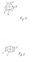
- Ausführungsbeispiele sind der Figuren-Beschreibung zu entnehmen. Es zeigen:
- Fig. 1
- eine schematische Darstellung eines vertikal angeordneten Fahrzeugmotors und
- Fig. 2
- eine schematische Darstellung eines vertikal angeordneten Fahrzeugmotors.
- Bei Fahrzeugen, bei welchen sich der Antriebsmotor 2 bei einer Lenkbewegung mitdreht, wie beispielsweise bei deichselgeführten Geräten, ist die Steuerung so um das Motorgehäuse zu verteilen, dass die Steuerung gleichmäßig den Radius des Motors 2 vergrößert, wodurch bei einer Drehung des Motors 2 die Steuerung 3 nicht mit anderen Bauteilen des Fahrzeugs kollidiert. In der Ausgestaltungsform der Fig. 3 ist die Steuerung 3 in drei Baugruppen aufgeteilt, welche gleichmäßig um die Drehachse des Antriebsmotors 2 verteilt angeordnet sind. Auch hier besteht die Möglichkeit, die Steuerung 3 mit dem Gehäuse des Antriebsmotors 2 zu verbinden oder das Gehäuse des Antriebsmotors 2 so auszubilden, dass die Steuerung 3 darin integriert ist. Eine Aufteilung in Leistungselektronik und Steuerelektronik ist ebenfalls möglich.
- Der Antriebsmotor 2 ist, wie der Antriebsmotor in
Fig. 1 , als mitdrehender Motor bei Lenkbewegungen ausgebildet, die Steuerung 3 ist jedoch in ihren Abmessungen so ausgebildet, dass sie innerhalb des Hüllkreises des Fahrzeugrades angeordnet werden kann, wodurch es ermöglicht wird, die elektronische Steuerung 3 in zwei Baugruppen aufzuteilen, welche sich gegenüberliegend am Umfang des Antriebsmotors 2 befinden. Ebenso besteht die Möglichkeit, bei Antrieben mit mitdrehenden Motoren die elektronische Steuerung so auszubilden, dass sie vollständig den Umfang des Antriebsmotors 2 umgibt. Indem die elektronische Steuerung 3 am Umfang des Antriebsmotors 2 angeordnet ist, wird der Antriebsmotor 2 nicht in vertikaler Richtung verlängert, was bei Antriebssystemen mit mitdrehenden Motoren aufgrund des geringen Bauraums in vertikaler Richtung durch eine vertikal über dem Motor angeordnete Steuerung nicht möglich ist. - In einer weiteren Ausgestaltungsform der
Fig. 1 bis 2 wird die elektronische Steuerung durch das Schmier- und Kühlmittel des Antriebsmotors oder des Untersetzungsgetriebes gekühlt. Hierbei wird die gesamte Oberfläche des Getriebegehäues zur Wärmeabfuhr benutzt, wodurch das Kühlschmiermittel gekühlt wird und wieder zur Wärmeaufnahme für die elektronische Steuerung bereit steht. Indem die elektronische Steuerung das Kühlschmiermittel erwärmt, wird auch das Untersetzungsgetriebe bzw. das Kühl- und Schmiermittel, welches das Untersetzungsgetriebe schmiert, schneller erwärmt, was zu einem besseren Wirkungsgrad, insbeondere in der Inbetriebnahmephase des Fahrzeugs, führt. - In einer weiteren Ausgestaltungsform der Erfindung besteht die Möglichkeit, das Gehäuse der elektronischen Steuerung bzw. das Gehäuse im Bereich der elektronischen Steuerung durch Kühlrippen zusätzlich zu kühlen. Ebenso besteht die Möglichkeit, Kanäle in das Gehäuse einzubringen, durch welche Kühlmittel oder Kühlluft strömt, um die elektronische Steuerung zu kühlen.
- Erfindungsgemäß wird ein Antrieb für Flurförderzeuge geschaffen, welcher sich durch eine geringere Verkabelung, verringerte Fehleranfälligkeit, insbesondere durch die Verringerung der Steck- und Schraubkontakte, sowie eine einfacherere Montage auszeichnet.
-
- 2
- Antriebsmotor
- 3
- elektronische Steuerung
Claims (5)
- Antrieb für ein Flurförderzeug, bei welchem ein Antriebsmotor (2) mit einer um eine Drehachse drehende Welle über ein Untersetzungsgetriebe ein Antriebsrad antreibt, wobei der Antriebsmotor (2) im eingebauten Zustand im Fahrzeug vertikal angeordnet ist, und das Antriebsrad im Sinne einer Lenkbewegung drehbar ausgeführt ist, wobei der Antriebsmotor (2) während der Lenkbewegung der Drehbewegung des Antriebsrades folgt, wobei eine elektronische Steuerung (3) parallel zur Drehachse der Welle am oder im Gehäuse des Antriebsmotors (2) angeordnet ist, dadurch gekennzeichnet, dass die Steuerung (3) verteilt um die Motorachse angeordnet ist.
- Antrieb nach Anspruch 1, dadurch gekennzeichnet, dass die elektronische Steuerung (3) durch das Kühlschmiermittel des Antriebes kühlbar ist.
- Antrieb nach einem der obigen Ansprüche, dadurch gekennzeichnet, dass die elektronische Steuerung (3) ein Gehäuse aufweist, an welchem Kühlrippen angeordnet sind.
- Antrieb nach einem der obigen Ansprüche, dadurch gekennzeichnet, dass das Gehäuse des Antriebes (1) Kanäle in Längsrichtung des Motors (2) aufweist, durch welche ein Kühlstrom in Form von Kühlmittel oder Luft leitbar ist.
- Antrieb nach einem der obigen Ansprüche, dadurch gekennzeichnet, dass die Motore und die Steuerung (3) bei Fremdkühlung mit dem gleichen Medium gleichzeitig gekühlt werden.
Applications Claiming Priority (2)
| Application Number | Priority Date | Filing Date | Title |
|---|---|---|---|
| DE102005017737A DE102005017737A1 (de) | 2005-04-15 | 2005-04-15 | Antrieb für ein Flurförderzeug |
| EP06723997A EP1868833B1 (de) | 2005-04-15 | 2006-04-04 | Antrieb für ein flurförderzeug |
Related Parent Applications (2)
| Application Number | Title | Priority Date | Filing Date |
|---|---|---|---|
| EP06723997A Division EP1868833B1 (de) | 2005-04-15 | 2006-04-04 | Antrieb für ein flurförderzeug |
| EP06723997.0 Division | 2006-04-04 |
Publications (2)
| Publication Number | Publication Date |
|---|---|
| EP2014500A1 EP2014500A1 (de) | 2009-01-14 |
| EP2014500B1 true EP2014500B1 (de) | 2011-09-14 |
Family
ID=36636939
Family Applications (2)
| Application Number | Title | Priority Date | Filing Date |
|---|---|---|---|
| EP06723997A Expired - Lifetime EP1868833B1 (de) | 2005-04-15 | 2006-04-04 | Antrieb für ein flurförderzeug |
| EP08165898A Expired - Lifetime EP2014500B1 (de) | 2005-04-15 | 2006-04-04 | Antrieb für ein Flurförderfahrzeug |
Family Applications Before (1)
| Application Number | Title | Priority Date | Filing Date |
|---|---|---|---|
| EP06723997A Expired - Lifetime EP1868833B1 (de) | 2005-04-15 | 2006-04-04 | Antrieb für ein flurförderzeug |
Country Status (5)
| Country | Link |
|---|---|
| US (1) | US7784572B2 (de) |
| EP (2) | EP1868833B1 (de) |
| AT (2) | ATE432843T1 (de) |
| DE (3) | DE102005017737A1 (de) |
| WO (1) | WO2006108531A2 (de) |
Families Citing this family (7)
| Publication number | Priority date | Publication date | Assignee | Title |
|---|---|---|---|---|
| DE102007043280A1 (de) | 2007-09-11 | 2009-03-12 | Jungheinrich Ag | Mitgehhubwagen |
| DE102009038651A1 (de) * | 2009-08-14 | 2011-02-24 | Jungheinrich Ag | Antriebsträger zur drehbaren Lagerung einer Antriebseinheit eines Flurförderzeugs |
| JP5917328B2 (ja) * | 2012-07-31 | 2016-05-11 | 住友重機械工業株式会社 | フォークリフト |
| WO2014142711A1 (ru) * | 2013-03-12 | 2014-09-18 | Общество с ограниченной ответственностью "Браво Моторс" | Электротрицикл, узел трансформации рамы электротрицикла и система рулевого управления электротрициклом с применением джойстика |
| CN103879283B (zh) | 2014-03-10 | 2019-01-15 | 浙江吉利汽车研究院有限公司 | 一种电动车辆 |
| CN112572120B (zh) | 2019-09-27 | 2025-09-16 | 罗伯特·博世有限公司 | 集成式电驱动系统和电动车辆 |
| CN111301517B (zh) * | 2020-03-13 | 2021-07-20 | 河南森源中锋智能制造有限公司 | Agv用舵轮及agv |
Family Cites Families (11)
| Publication number | Priority date | Publication date | Assignee | Title |
|---|---|---|---|---|
| US5128598A (en) * | 1990-12-13 | 1992-07-07 | Raymond Corporation | Material handling vehicle steering system |
| MY115442A (en) | 1994-08-04 | 2003-06-30 | Honda Motor Co Ltd | Motor with gear reducer |
| AUPO344896A0 (en) * | 1996-11-05 | 1996-12-05 | Grant, Brendan Joel | Eze the modular multifunction electric vehicle |
| DE10132318A1 (de) | 2001-07-06 | 2003-01-23 | Kordel Antriebstechnik Gmbh | Einradtriebwerk |
| DE10148457A1 (de) | 2001-10-01 | 2003-04-17 | Still Sarl | Kühlanordnung für eine Antriebseinheit |
| DE10204915A1 (de) | 2002-02-07 | 2003-09-11 | Zahnradfabrik Friedrichshafen | Antriebseinheit für Fahrzeug, insbesondere Hilfsantrieb für Handhubwagen |
| DE10241420A1 (de) | 2002-09-06 | 2004-03-18 | Still Gmbh | Flurförderzeug mit einem elektrischen Antrieb |
| DE10328651B4 (de) | 2003-06-26 | 2012-12-13 | Linde Material Handling Gmbh | Antriebseinheit mit einem Drehschemel, einem Fahrmotor und einem Lenkmotor |
| WO2005077695A1 (de) * | 2004-02-11 | 2005-08-25 | Zf Friedrichshafen Ag | Lenk-und radantrieb für ein flurförderzeug |
| DE102004006722A1 (de) | 2004-02-11 | 2005-09-01 | Zf Friedrichshafen Ag | Lenk- und Radantrieb für ein Flurförderzeug |
| DE102005058400A1 (de) * | 2005-11-30 | 2007-05-31 | Jungheinrich Ag | Antriebs- und Lenkeinheit für ein Rad eines Flurförderzeugs |
-
2005
- 2005-04-15 DE DE102005017737A patent/DE102005017737A1/de not_active Withdrawn
- 2005-04-15 DE DE202005020633U patent/DE202005020633U1/de not_active Expired - Lifetime
-
2006
- 2006-04-04 DE DE502006003887T patent/DE502006003887D1/de not_active Expired - Lifetime
- 2006-04-04 EP EP06723997A patent/EP1868833B1/de not_active Expired - Lifetime
- 2006-04-04 AT AT06723997T patent/ATE432843T1/de active
- 2006-04-04 US US11/911,385 patent/US7784572B2/en not_active Expired - Fee Related
- 2006-04-04 AT AT08165898T patent/ATE524340T1/de active
- 2006-04-04 WO PCT/EP2006/003039 patent/WO2006108531A2/de not_active Ceased
- 2006-04-04 EP EP08165898A patent/EP2014500B1/de not_active Expired - Lifetime
Also Published As
| Publication number | Publication date |
|---|---|
| EP1868833A2 (de) | 2007-12-26 |
| ATE432843T1 (de) | 2009-06-15 |
| EP2014500A1 (de) | 2009-01-14 |
| EP1868833B1 (de) | 2009-06-03 |
| WO2006108531A2 (de) | 2006-10-19 |
| ATE524340T1 (de) | 2011-09-15 |
| DE202005020633U1 (de) | 2006-10-26 |
| DE102005017737A1 (de) | 2006-10-26 |
| WO2006108531A3 (de) | 2007-03-22 |
| DE502006003887D1 (de) | 2009-07-16 |
| US7784572B2 (en) | 2010-08-31 |
| US20080190686A1 (en) | 2008-08-14 |
Similar Documents
| Publication | Publication Date | Title |
|---|---|---|
| DE60127462T2 (de) | Federbein, versehen mit Antriebsmitteln | |
| DE4425101C2 (de) | Elektrisch unterstütztes Lenk-Servosystem | |
| EP2014500B1 (de) | Antrieb für ein Flurförderfahrzeug | |
| DE102011087602A1 (de) | Elektrische Maschine | |
| EP1574714B1 (de) | Pumpenaggregat | |
| DE102009037672B4 (de) | Lenkvorrichtung für ein Kraftfahrzeug mit einem Lenkrad und einer elektronischen Kontakteinheit | |
| EP1928680B1 (de) | Antriebseinheit mit optimierter kühlung | |
| DE10307566A1 (de) | Elektrohydraulisches Doppelpumpen-Doppelmotor-Aggregat für eine selbstfahrende Arbeitsmaschine, insbesondere Flurförderzeug | |
| EP0582217B1 (de) | Kühlflüssigkeitsgekühltes Stromrichtermodul mit einer durch eine Kühlmittelpumpe erzeugten Kühlflüssigkeitsströmung | |
| DE10339433A1 (de) | Selbsttragendes Antriebsmodul | |
| DE102013112841A1 (de) | Lenksystem | |
| EP1940723B1 (de) | Antriebseinheit | |
| DE102011075706A1 (de) | Antriebsmodul mit Differentialgehäuse und darin integrierten Kabelverschraubungen | |
| EP0467151B1 (de) | Kraftfahrzeug mit einer elektrischen Steuerung mit wärmeabgebenden Bauelementen | |
| DE202005020624U1 (de) | Antriebseinheit mit optimierter Kühlung | |
| DE10148457A1 (de) | Kühlanordnung für eine Antriebseinheit | |
| EP3802019B1 (de) | Antriebsvorrichtung für einen manipulator | |
| EP1378319B1 (de) | Antriebssystem mit Linearmotoren sowie Vorschubachse einer Werkzeugmaschine mit einem solchen Antriebssystem | |
| DE102021103815A1 (de) | Pumpeinrichtung für eine Lenkvorrichtung eines Fahrzeugs, Lenkvorrichtung und Verfahren und Vorrichtung zum Herstellen einer Pumpeinrichtung | |
| DE202005020629U1 (de) | Antriebseinheit | |
| DE10312431A1 (de) | Kühlluftführung in einem Flurförderzeug | |
| DE102020120756A1 (de) | Radantrieb sowie Kraftfahrzeug | |
| DE19800895B4 (de) | Kühlgebläse | |
| DE102013110569A1 (de) | Sensoranordnung und Antriebsachse mit Sensoranordnung | |
| DE102023211129A1 (de) | Radmotor mit radintegrierter Steuerung und Radbremse |
Legal Events
| Date | Code | Title | Description |
|---|---|---|---|
| PUAI | Public reference made under article 153(3) epc to a published international application that has entered the european phase |
Free format text: ORIGINAL CODE: 0009012 |
|
| PUAI | Public reference made under article 153(3) epc to a published international application that has entered the european phase |
Free format text: ORIGINAL CODE: 0009012 |
|
| 17P | Request for examination filed |
Effective date: 20081006 |
|
| AC | Divisional application: reference to earlier application |
Ref document number: 1868833 Country of ref document: EP Kind code of ref document: P |
|
| AK | Designated contracting states |
Kind code of ref document: A1 Designated state(s): AT BE BG CH CY CZ DE DK EE ES FI FR GB GR HU IE IS IT LI LT LU LV MC NL PL PT RO SE SI SK TR |
|
| AX | Request for extension of the european patent |
Extension state: AL BA HR MK YU |
|
| AKX | Designation fees paid |
Designated state(s): AT BE BG CH CY CZ DE DK EE ES FI FR GB GR HU IE IS IT LI LT LU LV MC NL PL PT RO SE SI SK TR |
|
| GRAP | Despatch of communication of intention to grant a patent |
Free format text: ORIGINAL CODE: EPIDOSNIGR1 |
|
| RIC1 | Information provided on ipc code assigned before grant |
Ipc: B60K 17/04 20060101ALI20110407BHEP Ipc: B66F 9/075 20060101ALI20110407BHEP Ipc: B60K 17/30 20060101ALI20110407BHEP Ipc: B60K 7/00 20060101AFI20110407BHEP |
|
| GRAS | Grant fee paid |
Free format text: ORIGINAL CODE: EPIDOSNIGR3 |
|
| GRAA | (expected) grant |
Free format text: ORIGINAL CODE: 0009210 |
|
| RIN1 | Information on inventor provided before grant (corrected) |
Inventor name: STREIPARDT, PETER Inventor name: HABEL, MATTHIAS Inventor name: BALD, DIRK |
|
| AC | Divisional application: reference to earlier application |
Ref document number: 1868833 Country of ref document: EP Kind code of ref document: P |
|
| AK | Designated contracting states |
Kind code of ref document: B1 Designated state(s): AT BE BG CH CY CZ DE DK EE ES FI FR GB GR HU IE IS IT LI LT LU LV MC NL PL PT RO SE SI SK TR |
|
| REG | Reference to a national code |
Ref country code: GB Ref legal event code: FG4D Free format text: NOT ENGLISH |
|
| REG | Reference to a national code |
Ref country code: CH Ref legal event code: EP |
|
| REG | Reference to a national code |
Ref country code: IE Ref legal event code: FG4D Free format text: LANGUAGE OF EP DOCUMENT: GERMAN |
|
| REG | Reference to a national code |
Ref country code: DE Ref legal event code: R096 Ref document number: 502006010200 Country of ref document: DE Effective date: 20111110 |
|
| REG | Reference to a national code |
Ref country code: NL Ref legal event code: VDEP Effective date: 20110914 |
|
| PG25 | Lapsed in a contracting state [announced via postgrant information from national office to epo] |
Ref country code: LT Free format text: LAPSE BECAUSE OF FAILURE TO SUBMIT A TRANSLATION OF THE DESCRIPTION OR TO PAY THE FEE WITHIN THE PRESCRIBED TIME-LIMIT Effective date: 20110914 Ref country code: SE Free format text: LAPSE BECAUSE OF FAILURE TO SUBMIT A TRANSLATION OF THE DESCRIPTION OR TO PAY THE FEE WITHIN THE PRESCRIBED TIME-LIMIT Effective date: 20110914 Ref country code: FI Free format text: LAPSE BECAUSE OF FAILURE TO SUBMIT A TRANSLATION OF THE DESCRIPTION OR TO PAY THE FEE WITHIN THE PRESCRIBED TIME-LIMIT Effective date: 20110914 |
|
| LTIE | Lt: invalidation of european patent or patent extension |
Effective date: 20110914 |
|
| PG25 | Lapsed in a contracting state [announced via postgrant information from national office to epo] |
Ref country code: SI Free format text: LAPSE BECAUSE OF FAILURE TO SUBMIT A TRANSLATION OF THE DESCRIPTION OR TO PAY THE FEE WITHIN THE PRESCRIBED TIME-LIMIT Effective date: 20110914 Ref country code: CY Free format text: LAPSE BECAUSE OF FAILURE TO SUBMIT A TRANSLATION OF THE DESCRIPTION OR TO PAY THE FEE WITHIN THE PRESCRIBED TIME-LIMIT Effective date: 20110914 Ref country code: LV Free format text: LAPSE BECAUSE OF FAILURE TO SUBMIT A TRANSLATION OF THE DESCRIPTION OR TO PAY THE FEE WITHIN THE PRESCRIBED TIME-LIMIT Effective date: 20110914 Ref country code: GR Free format text: LAPSE BECAUSE OF FAILURE TO SUBMIT A TRANSLATION OF THE DESCRIPTION OR TO PAY THE FEE WITHIN THE PRESCRIBED TIME-LIMIT Effective date: 20111215 |
|
| REG | Reference to a national code |
Ref country code: IE Ref legal event code: FD4D |
|
| PG25 | Lapsed in a contracting state [announced via postgrant information from national office to epo] |
Ref country code: IS Free format text: LAPSE BECAUSE OF FAILURE TO SUBMIT A TRANSLATION OF THE DESCRIPTION OR TO PAY THE FEE WITHIN THE PRESCRIBED TIME-LIMIT Effective date: 20120114 Ref country code: CZ Free format text: LAPSE BECAUSE OF FAILURE TO SUBMIT A TRANSLATION OF THE DESCRIPTION OR TO PAY THE FEE WITHIN THE PRESCRIBED TIME-LIMIT Effective date: 20110914 Ref country code: IE Free format text: LAPSE BECAUSE OF FAILURE TO SUBMIT A TRANSLATION OF THE DESCRIPTION OR TO PAY THE FEE WITHIN THE PRESCRIBED TIME-LIMIT Effective date: 20110914 Ref country code: SK Free format text: LAPSE BECAUSE OF FAILURE TO SUBMIT A TRANSLATION OF THE DESCRIPTION OR TO PAY THE FEE WITHIN THE PRESCRIBED TIME-LIMIT Effective date: 20110914 |
|
| PG25 | Lapsed in a contracting state [announced via postgrant information from national office to epo] |
Ref country code: IT Free format text: LAPSE BECAUSE OF FAILURE TO SUBMIT A TRANSLATION OF THE DESCRIPTION OR TO PAY THE FEE WITHIN THE PRESCRIBED TIME-LIMIT Effective date: 20110914 Ref country code: PL Free format text: LAPSE BECAUSE OF FAILURE TO SUBMIT A TRANSLATION OF THE DESCRIPTION OR TO PAY THE FEE WITHIN THE PRESCRIBED TIME-LIMIT Effective date: 20110914 Ref country code: RO Free format text: LAPSE BECAUSE OF FAILURE TO SUBMIT A TRANSLATION OF THE DESCRIPTION OR TO PAY THE FEE WITHIN THE PRESCRIBED TIME-LIMIT Effective date: 20110914 Ref country code: PT Free format text: LAPSE BECAUSE OF FAILURE TO SUBMIT A TRANSLATION OF THE DESCRIPTION OR TO PAY THE FEE WITHIN THE PRESCRIBED TIME-LIMIT Effective date: 20120116 Ref country code: NL Free format text: LAPSE BECAUSE OF FAILURE TO SUBMIT A TRANSLATION OF THE DESCRIPTION OR TO PAY THE FEE WITHIN THE PRESCRIBED TIME-LIMIT Effective date: 20110914 Ref country code: EE Free format text: LAPSE BECAUSE OF FAILURE TO SUBMIT A TRANSLATION OF THE DESCRIPTION OR TO PAY THE FEE WITHIN THE PRESCRIBED TIME-LIMIT Effective date: 20110914 |
|
| PLBE | No opposition filed within time limit |
Free format text: ORIGINAL CODE: 0009261 |
|
| STAA | Information on the status of an ep patent application or granted ep patent |
Free format text: STATUS: NO OPPOSITION FILED WITHIN TIME LIMIT |
|
| PG25 | Lapsed in a contracting state [announced via postgrant information from national office to epo] |
Ref country code: DK Free format text: LAPSE BECAUSE OF FAILURE TO SUBMIT A TRANSLATION OF THE DESCRIPTION OR TO PAY THE FEE WITHIN THE PRESCRIBED TIME-LIMIT Effective date: 20110914 |
|
| 26N | No opposition filed |
Effective date: 20120615 |
|
| REG | Reference to a national code |
Ref country code: DE Ref legal event code: R097 Ref document number: 502006010200 Country of ref document: DE Effective date: 20120615 |
|
| BERE | Be: lapsed |
Owner name: ZF FRIEDRICHSHAFEN A.G. Effective date: 20120430 |
|
| PG25 | Lapsed in a contracting state [announced via postgrant information from national office to epo] |
Ref country code: MC Free format text: LAPSE BECAUSE OF NON-PAYMENT OF DUE FEES Effective date: 20120430 |
|
| REG | Reference to a national code |
Ref country code: CH Ref legal event code: PL |
|
| GBPC | Gb: european patent ceased through non-payment of renewal fee |
Effective date: 20120404 |
|
| REG | Reference to a national code |
Ref country code: FR Ref legal event code: ST Effective date: 20121228 |
|
| PG25 | Lapsed in a contracting state [announced via postgrant information from national office to epo] |
Ref country code: BE Free format text: LAPSE BECAUSE OF NON-PAYMENT OF DUE FEES Effective date: 20120430 Ref country code: GB Free format text: LAPSE BECAUSE OF NON-PAYMENT OF DUE FEES Effective date: 20120404 Ref country code: CH Free format text: LAPSE BECAUSE OF NON-PAYMENT OF DUE FEES Effective date: 20120430 Ref country code: LI Free format text: LAPSE BECAUSE OF NON-PAYMENT OF DUE FEES Effective date: 20120430 |
|
| PG25 | Lapsed in a contracting state [announced via postgrant information from national office to epo] |
Ref country code: FR Free format text: LAPSE BECAUSE OF NON-PAYMENT OF DUE FEES Effective date: 20120430 |
|
| PG25 | Lapsed in a contracting state [announced via postgrant information from national office to epo] |
Ref country code: ES Free format text: LAPSE BECAUSE OF FAILURE TO SUBMIT A TRANSLATION OF THE DESCRIPTION OR TO PAY THE FEE WITHIN THE PRESCRIBED TIME-LIMIT Effective date: 20111225 |
|
| REG | Reference to a national code |
Ref country code: AT Ref legal event code: MM01 Ref document number: 524340 Country of ref document: AT Kind code of ref document: T Effective date: 20120404 |
|
| PG25 | Lapsed in a contracting state [announced via postgrant information from national office to epo] |
Ref country code: BG Free format text: LAPSE BECAUSE OF FAILURE TO SUBMIT A TRANSLATION OF THE DESCRIPTION OR TO PAY THE FEE WITHIN THE PRESCRIBED TIME-LIMIT Effective date: 20111214 |
|
| PG25 | Lapsed in a contracting state [announced via postgrant information from national office to epo] |
Ref country code: AT Free format text: LAPSE BECAUSE OF NON-PAYMENT OF DUE FEES Effective date: 20120404 |
|
| PG25 | Lapsed in a contracting state [announced via postgrant information from national office to epo] |
Ref country code: TR Free format text: LAPSE BECAUSE OF FAILURE TO SUBMIT A TRANSLATION OF THE DESCRIPTION OR TO PAY THE FEE WITHIN THE PRESCRIBED TIME-LIMIT Effective date: 20110914 |
|
| PG25 | Lapsed in a contracting state [announced via postgrant information from national office to epo] |
Ref country code: LU Free format text: LAPSE BECAUSE OF NON-PAYMENT OF DUE FEES Effective date: 20120404 |
|
| PG25 | Lapsed in a contracting state [announced via postgrant information from national office to epo] |
Ref country code: HU Free format text: LAPSE BECAUSE OF FAILURE TO SUBMIT A TRANSLATION OF THE DESCRIPTION OR TO PAY THE FEE WITHIN THE PRESCRIBED TIME-LIMIT Effective date: 20060404 |
|
| PGFP | Annual fee paid to national office [announced via postgrant information from national office to epo] |
Ref country code: DE Payment date: 20160330 Year of fee payment: 11 |
|
| REG | Reference to a national code |
Ref country code: DE Ref legal event code: R119 Ref document number: 502006010200 Country of ref document: DE |
|
| PG25 | Lapsed in a contracting state [announced via postgrant information from national office to epo] |
Ref country code: DE Free format text: LAPSE BECAUSE OF NON-PAYMENT OF DUE FEES Effective date: 20171103 |