EP2014536B1 - Poussette pliable en jouet - Google Patents
Poussette pliable en jouet Download PDFInfo
- Publication number
- EP2014536B1 EP2014536B1 EP07013781A EP07013781A EP2014536B1 EP 2014536 B1 EP2014536 B1 EP 2014536B1 EP 07013781 A EP07013781 A EP 07013781A EP 07013781 A EP07013781 A EP 07013781A EP 2014536 B1 EP2014536 B1 EP 2014536B1
- Authority
- EP
- European Patent Office
- Prior art keywords
- central rod
- sliding seat
- rods
- locking member
- toy stroller
- Prior art date
- Legal status (The legal status is an assumption and is not a legal conclusion. Google has not performed a legal analysis and makes no representation as to the accuracy of the status listed.)
- Not-in-force
Links
- 230000001154 acute effect Effects 0.000 claims description 7
- 239000004744 fabric Substances 0.000 description 1
Images





Classifications
-
- B—PERFORMING OPERATIONS; TRANSPORTING
- B62—LAND VEHICLES FOR TRAVELLING OTHERWISE THAN ON RAILS
- B62B—HAND-PROPELLED VEHICLES, e.g. HAND CARTS OR PERAMBULATORS; SLEDGES
- B62B7/00—Carriages for children; Perambulators, e.g. dolls' perambulators
- B62B7/04—Carriages for children; Perambulators, e.g. dolls' perambulators having more than one wheel axis; Steering devices therefor
- B62B7/06—Carriages for children; Perambulators, e.g. dolls' perambulators having more than one wheel axis; Steering devices therefor collapsible or foldable
- B62B7/08—Carriages for children; Perambulators, e.g. dolls' perambulators having more than one wheel axis; Steering devices therefor collapsible or foldable in the direction of, or at right angles to, the wheel axis
-
- B—PERFORMING OPERATIONS; TRANSPORTING
- B62—LAND VEHICLES FOR TRAVELLING OTHERWISE THAN ON RAILS
- B62B—HAND-PROPELLED VEHICLES, e.g. HAND CARTS OR PERAMBULATORS; SLEDGES
- B62B7/00—Carriages for children; Perambulators, e.g. dolls' perambulators
- B62B7/04—Carriages for children; Perambulators, e.g. dolls' perambulators having more than one wheel axis; Steering devices therefor
- B62B7/06—Carriages for children; Perambulators, e.g. dolls' perambulators having more than one wheel axis; Steering devices therefor collapsible or foldable
- B62B7/068—Carriages for children; Perambulators, e.g. dolls' perambulators having more than one wheel axis; Steering devices therefor collapsible or foldable by sliding a bushing along a rod, e.g. like folding means of an umbrella
-
- B—PERFORMING OPERATIONS; TRANSPORTING
- B62—LAND VEHICLES FOR TRAVELLING OTHERWISE THAN ON RAILS
- B62B—HAND-PROPELLED VEHICLES, e.g. HAND CARTS OR PERAMBULATORS; SLEDGES
- B62B2205/00—Hand-propelled vehicles or sledges being foldable or dismountable when not in use
- B62B2205/003—Hand-propelled vehicles or sledges being foldable or dismountable when not in use with actuation mechanisms which drive the folding or unfolding operation
-
- B—PERFORMING OPERATIONS; TRANSPORTING
- B62—LAND VEHICLES FOR TRAVELLING OTHERWISE THAN ON RAILS
- B62B—HAND-PROPELLED VEHICLES, e.g. HAND CARTS OR PERAMBULATORS; SLEDGES
- B62B2205/00—Hand-propelled vehicles or sledges being foldable or dismountable when not in use
- B62B2205/02—Hand-propelled vehicles or sledges being foldable or dismountable when not in use foldable widthwise
-
- B—PERFORMING OPERATIONS; TRANSPORTING
- B62—LAND VEHICLES FOR TRAVELLING OTHERWISE THAN ON RAILS
- B62B—HAND-PROPELLED VEHICLES, e.g. HAND CARTS OR PERAMBULATORS; SLEDGES
- B62B2205/00—Hand-propelled vehicles or sledges being foldable or dismountable when not in use
- B62B2205/20—Catches; Locking or releasing an articulation
-
- B—PERFORMING OPERATIONS; TRANSPORTING
- B62—LAND VEHICLES FOR TRAVELLING OTHERWISE THAN ON RAILS
- B62B—HAND-PROPELLED VEHICLES, e.g. HAND CARTS OR PERAMBULATORS; SLEDGES
- B62B2205/00—Hand-propelled vehicles or sledges being foldable or dismountable when not in use
- B62B2205/20—Catches; Locking or releasing an articulation
- B62B2205/23—Catches; Locking or releasing an articulation foot operated
-
- B—PERFORMING OPERATIONS; TRANSPORTING
- B62—LAND VEHICLES FOR TRAVELLING OTHERWISE THAN ON RAILS
- B62B—HAND-PROPELLED VEHICLES, e.g. HAND CARTS OR PERAMBULATORS; SLEDGES
- B62B2205/00—Hand-propelled vehicles or sledges being foldable or dismountable when not in use
- B62B2205/20—Catches; Locking or releasing an articulation
- B62B2205/24—Catches; Locking or releasing an articulation to hold in the folded position
-
- B—PERFORMING OPERATIONS; TRANSPORTING
- B62—LAND VEHICLES FOR TRAVELLING OTHERWISE THAN ON RAILS
- B62B—HAND-PROPELLED VEHICLES, e.g. HAND CARTS OR PERAMBULATORS; SLEDGES
- B62B7/00—Carriages for children; Perambulators, e.g. dolls' perambulators
- B62B7/04—Carriages for children; Perambulators, e.g. dolls' perambulators having more than one wheel axis; Steering devices therefor
- B62B7/044—Carriages for children; Perambulators, e.g. dolls' perambulators having more than one wheel axis; Steering devices therefor three wheeled
-
- B—PERFORMING OPERATIONS; TRANSPORTING
- B62—LAND VEHICLES FOR TRAVELLING OTHERWISE THAN ON RAILS
- B62B—HAND-PROPELLED VEHICLES, e.g. HAND CARTS OR PERAMBULATORS; SLEDGES
- B62B7/00—Carriages for children; Perambulators, e.g. dolls' perambulators
- B62B7/04—Carriages for children; Perambulators, e.g. dolls' perambulators having more than one wheel axis; Steering devices therefor
- B62B7/06—Carriages for children; Perambulators, e.g. dolls' perambulators having more than one wheel axis; Steering devices therefor collapsible or foldable
- B62B7/062—Coupling unit between front wheels, rear wheels and handle
Definitions
- the present invention relates to a toy stroller and, more particularly, to a foldable three-wheel toy stroller.
- Strollers for carrying babies or toy strollers for carrying dolls generally include two handles, a frame, and wheels.
- the frame generally includes joints that are pivotable to allow folding and that can be locked when folded or extended.
- the frames of toy strollers are generally folded in the front/rear direction in which the front and rear wheels are adjacent to each other after folding.
- Document EP 1 466 810 represents the closest prior art and discloses a foldable stroller with
- a foldable stroller including two main rods and two extension rods each having an upper end mounted to a lower end of one of the main rods and a lower end rotatably mounted to an end of a front-wheel base to which a front wheel is mounted.
- a central rod includes a first end connected to the front-wheel base and a second end to which a locking member is mounted.
- a sliding seat is slideably mounted on the central rod and includes a positioning hole for receiving a locking portion of the locking member.
- Two rear wheel support rods are provided and each include a first end pivotably connected to the front wheel base and a second end to which a rear wheel is mounted.
- Pivotably connected to the sliding seat are two struts whose upper ends are pivotably connected to upper ends of the main rods.
- Two connecting rods are pivotably connected between the rear wheel support rods and the sliding seat.
- Each rear wheel support rod and each connecting rod are pivotable away from the central rod for unfolding the foldable toy stroller or toward the central rod for folding the foldable toy stroller.
- the locking portion of the locking member is engaged in the positioning hole of the sliding seat when the foldable toy stroller is in an extended state.
- the struts are away from the central rod and stretch the main rods upward.
- the connecting rods are away from the central rod and stretch the rear wheel support rods outward away from the central rod.
- the sliding seat is slidable on the central rod when the locking portion of the locking member is disengaged from the positioning hole of the sliding seat, allowing the main rods, the rear wheel support rods, the struts, and the connecting rods to pivot toward the central rod for folding the foldable toy stroller.
- the sliding seat includes four connecting portions to which the lower ends of the struts and the second ends of the connecting rods are pivotably connected.
- the sliding seat includes a longitudinal hole that slideably receives the central rod.
- the positioning hole of the sliding seat is in communication with and transverse to the longitudinal hole.
- the sliding seat further includes a guiding groove extending parallel to the longitudinal hole and in communication with the positioning hole.
- the locking portion is slideable in the guiding groove when the sliding seat is slideable on the central rod.
- a spring is mounted in the central rod for biasing the locking portion and an engaging portion of the locking member to respectively engage with the positioning hole of the sliding seat and an engaging hole of a handle mounted on the central rod.
- a push button is received in the engaging hole of the handle and can be pressed to disengage the engaging portion of the locking member from the engaging hole of the handle and to disengage the locking portion of the locking member from the positioning hole of the sliding seat to allow sliding movement of the sliding seat along the central rod.
- a front wheel is attached to a vertical portion extending downward from an intermediate portion between the ends of the front-wheel base.
- a horizontal portion extends horizontally from the intermediate portion and includes an end to which a coupler is mounted. The first end of the central rod is coupled to the coupler.
- the coupler further includes two pairs of lugs on an outer periphery thereof, and the front end of each rear wheel support rod is pivotably received between a pair of lugs.
- a stud extends outward from an end face of each end of the front-wheel base an acute angle with a longitudinal axis of the central rod.
- the lower end of each extension rod includes an eccentric hole parallel to and spaced from a central portion thereof.
- Each stud rotatably extends through the eccentric hole of the lower end of one of the extension rods.
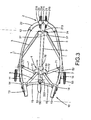
- a foldable toy stroller according to the preferred teachings of the present invention is shown in the drawings and generally designated 10.
- the foldable toy stroller 10 includes a pair of main rods 1 to which a piece of cloth 16 is attached for providing a seat and a backrest for a doll or a baby.
- a handgrip 13 is mounted to an upper end 11 of each main rod 1.
- a pair of links 5 is mounted between the couplers 14. Inner ends of the links 5 are pivotably connected together and pivotable about a pivot axis 150. Outer ends of the links 5 are respectively and pivotably connected to the couplers 14.
- the links 5 are substantially in the same line when the foldable toy stroller 10 is in its extended state.
- the foldable toy stroller 10 further includes a linking device 2.
- the linking device 2 includes a front-wheel base 21 and two substantially arc-shaped extension rods 22 respectively on two ends 215 of the front-wheel base 21.
- a horizontal portion 211 extends horizontally from an intermediate portion of the front-wheel base 21. Specifically, the horizontal portion 211 has a first end 213 and a second end 214 coupled to the front-wheel base 21.
- a vertical portion 212 extends downward from the intermediate portion of the front-wheel base 21, and a front wheel 23 is attached to a lower end of the vertical portion 212.
- Each extension rod 22 includes a lower end 221 pivotably connected to one of the ends 215 of the front-wheel base 21.
- Each extension rod 22 further includes an upper end 222 fixed to a lower end 12 of one of the main rods 1.
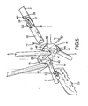
- the main rods 1 and the extension rods 22 can pivot relative to the front-wheel base 21 (see FIG. 2 ).
- a stud 216 is formed on an end face of each end 215 of the front-wheel base 21.
- the stud 216 defines a pivot axis in an acute angle with a longitudinal axis of the central rod 3.
- the lower end 221 of each extension rod 22 includes a protrusion 224 on an outer periphery thereof.
- the protrusion 224 includes an eccentric through-hole 223 (see FIG.
- the central rod 3 includes a first end 31 fixed to the first end 213 of the horizontal extension 211 and a second end 32 to which a handle 33 is mounted.
- a coupler 24 is provided between the first end 31 of the central rod 3 and the first end 213 of the horizontal extension 211.
- Two pairs of lugs 240 are formed on an outer periphery of the coupler 24.
- the second end 32 of the central rod 3 includes a first slot 35 and a second slot 36.
- a locking member 34 is slideably mounted in the second end 32 of the central rod 3 in a direction perpendicular to the longitudinal axis of the central rod 3.
- the locking member 34 includes a locking portion 341 slideably extending through the first slot 35 and an engaging portion 342 slideably extending through the second slot 36.
- a spring 37 is mounted in the second end 32 of the central rod 3 for biasing the locking portion 341 and the engaging portion 342 of the locking member 34 to their protruded positions outside the central rod 3.
- the handle 33 includes an engaging hole 331 for receiving the engaging portion 342 of the locking member 34.
- a push button 332 is slideably received in the engaging hole 331 and operatively connected to the engaging portion 342 of the locking member 34.
- the engaging portion 342 of the locking member 34 is received in the engaging hole 331 of the handle 33 to couple the handle 33 to the central rod 3.
- a sliding seat 4 is slideably mounted on the second end 32 of the central rod 3.
- the sliding seat 4 includes a longitudinal hole 41 that slideably receives the central rod 3.
- the sliding seat 4 further includes a positioning hole 42 in a periphery thereof and in communication with and transverse to the longitudinal hole 41.
- the positioning hole 42 releasably receives the locking portion 341 of the locking member 34. Specifically, when the sliding seat 4 is in a position where the positioning hole 42 of the sliding seat 4 is aligned with the locking portion 341 of the locking member 34, the locking portion 341 of the locking member 34 is moved into the positioning hole 42 of the sliding seat 4 under the action of the spring 37, thereby engaging the sliding seat 4 with the central rod 3.
- the sliding seat 4 further includes a guiding groove 43 extending in a longitudinal direction parallel to the longitudinal hole 41 and in communication with the positioning hole 42.
- a guiding groove 43 extending in a longitudinal direction parallel to the longitudinal hole 41 and in communication with the positioning hole 42.
- the foldable toy stroller 10 further includes a pair of struts 6 each including a lower end 62 pivotably received in the compartment 45 of one of the connecting portions 44.
- Each strut 6 further includes an upper end 61 pivotably connected to a coupler 17 mounted to the upper end 11 of one of the main beams 1.
- Each strut 6 is pivotable toward or away from the central rod 3 substantially in a plane parallel to the longitudinal axis of the central rod 3 to allow folding/unfolding operation.
- the foldable toy stroller 10 further includes a pair of rear wheel support rods 5 each including a first end 51 pivotally received between a pair of lugs 240 on the coupler 24.
- Each rear wheel support rod 5 further includes a second end 52 to which a rear wheel 53 is mounted.
- a coupler 54 is mounted on the second end 52 of each rear wheel support rod 5 for pivotable connection with a first end 71 of a connecting rod 7 whose second end 72 is pivotably received in the compartment 45 of one of the connecting portions 44.
- the rear wheel support rods 5 may pivot toward or away from the central rod 3 to allow folding/unfolding operation.
- the connecting rods 7 may pivot toward or away from the central rod 3 to allow folding/unfolding operation.
- each of the rear wheel support rods 5 and the connecting rods 7 is pivotable away from the central rod 3 for unfolding operation or toward the central rod 3 for folding operation.
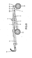
- the sliding seat 4 When the foldable toy stroller 10 according to the preferred teachings of the present invention is in its extended state, the sliding seat 4 is in a position where the positioning hole 42 of the sliding seat 4 is aligned with the locking portion 341 of the locking member 34, the locking portion 341 of the locking member 34 is moved into the positioning hole 42 of the sliding seat 4 under the action of the spring 37, thereby fixing the sliding seat 4 on the central rod 3.
- the struts 6 are at a small acute angle with a vertical plane orthogonal to the longitudinal axis of the central rod 3 to stretch the upper ends 11 of the main rods 1 upward whereas the links 15 are collinear to stretch the upper ends 11 of the main rods 1 outward.
- the connecting rods 7 are away from the central rod 3 and away from each other and, thus, stretch the rear wheel support rods 5 away from the central rod 3.
- the frame thus formed has a strong structure to assure safety.
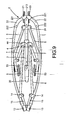
- the push button 332 on the handle 33 is pressed to disengage the locking portion 332 of the locking member 34 from the positioning hole 42 of the sliding seat 4, unlocking engagement between the central rod 3 and the sliding seat 4.
- the sliding seat 4 is slid toward the first end 31 of the central rod 3, which causes the lower ends 62 of the struts 6 and the second ends 72 of the connecting rods 7 move forward together with the sliding seat 4.
- the struts 6 pivot downward to a position at a small acute angle with the longitudinal axis of the central rod 3.
- the connecting rods 7 and the rear wheel support rods 5 pivot toward the central rod 3.
- the outer ends of the links 15 pivot inward toward each other.
- both the width and the height of the folded stroller 10 according to the preferred teachings of the present invention are reduced with simple folding operation, allowing easy storage and transport.
- the angle between the central rod 3 and the struts 6 in the extended state and the folded state may vary. Furthermore, the extending planes of the struts 6, the connecting rods 7, the rear wheel support rods 5, the extension rods 22, and the main rods 1 may vary according to product needs.
Landscapes
- Engineering & Computer Science (AREA)
- Chemical & Material Sciences (AREA)
- Combustion & Propulsion (AREA)
- Transportation (AREA)
- Mechanical Engineering (AREA)
- Carriages For Children, Sleds, And Other Hand-Operated Vehicles (AREA)
- Toys (AREA)
Claims (9)
- Poussette pliable en jouet comprenant :• deux tiges principales (1) présentant chacune une extrémité supérieure (11) et une extrémité inférieure (12) ;• une base pour roue avant (21) présentant deux extrémités (215) ;• deux tiges de prolongation (22) comprenant chacune une extrémité supérieure (222) montée sur l'extrémité inférieure (12) d'une des tiges principales (1) et une extrémité inférieure (221) raccordée à pivotement à une des extrémités (215) de la base pour roue avant (21) ;• une tige centrale (3) présentant une première extrémité (31) reliée à la base pour roue avant (21) et une seconde extrémité (32), un élément de verrouillage (34) monté dans la seconde extrémité (32) de la tige centrale (3) et comportant une partie de verrouillage (341) ;• un siège coulissant (4) monté coulissant sur la tige centrale (3) et présentant un orifice de positionnement (42) pour recevoir la partie de verrouillage (341) de l'élément de verrouillage (34) ;• deux tiges de support pour roue arrière (5) présentant chacune une première extrémité (51) raccordée à pivotement à la base pour roue avant (21) et une seconde extrémité (52) sur laquelle une roue arrière (53) est montée ;• deux entretoises (6) présentant chacune une extrémité supérieure (61) raccordée à pivotement à l'extrémité supérieure (11) d'une des tiges principales (1) et une extrémité inférieure (62) raccordée à pivotement au siège coulissant (4) ; et• deux tiges de jonction (7) présentant chacune une première extrémité (71) raccordée à pivotement à une des tiges de support pour roue arrière (5) et une seconde extrémité (72) raccordée à pivotement au siège coulissant (4), chacune des tiges de support pour roue arrière (5) et des tiges de jonction (7) pouvant être pivotée en éloignement de la tige centrale (3) pour déployer la poussette pliable en jouet ou vers la tige centrale (3) pour replier la poussette pliable en jouet,
la partie de verrouillage (341) de l'élément de verrouillage (34) étant engagée dans l'orifice de positionnement (42) du siège coulissant (4) lorsque la poussette pliable en jouet est à l'état déployé, les entretoises (6) étant éloignées de la tige centrale (3) et tendant les tiges principales (1) vers le haut, et les tiges de jonction (7) étant éloignées de la tige centrale (3) et tendant les tiges de support pour roue arrière (5) vers l'extérieur en éloignement de la tige centrale (3), et le siège coulissant (4) pouvant coulisser sur la tige centrale (3) lorsque la partie de verrouillage (341) de l'élément de verrouillage (34) est désengagée de l'orifice de positionnement (42) du siège coulissant (4), permettant aux tiges principales (1), aux tiges de support pour roue arrière (5), aux entretoises (6) et aux tiges de jonction (7) de pivoter vers la tige centrale (3) pour replier la poussette pliable en jouet. - Poussette pliable en jouet selon la revendication 1, comportant en outre, en association : un dispositif d'accouplement (14) monté sur l'extrémité supérieure (11) de chacune des tiges principales (1) ; et deux liaisons (15) montées entre les tiges principales (1) et présentant chacune une extrémité interne et une extrémité externe, les extrémités internes des liaisons (15) étant reliées entre elles à pivotement, et les extrémités externes des liaisons (15) étant reliées respectivement à pivotement aux dispositif d'accouplements (14).
- Poussette pliable en jouet selon la revendication 1, le siège coulissant (4) comprenant en outre quatre parties de jonction (44) auxquelles les extrémités inférieures (62) des entretoises (6) et les secondes extrémités (72) des tiges de jonction (7) sont raccordées à pivotement.
- Poussette pliable en jouet selon la revendication 1, le siège coulissant (4) comprenant un orifice longitudinal (41) qui reçoit la tige centrale (3) à coulissement, l'orifice de positionnement (42) du siège coulissant (4) étant en communication et transversal à l'orifice longitudinal (41), le siège coulissant (4) comprenant en outre une gorge de guidage (43) s'étendant parallèle à l'orifice longitudinal (41) et en communication avec l'orifice de positionnement (42), et la partie de verrouillage (341) pouvant coulisser dans la gorge de guidage (43) lorsque le siège coulissant (4) coulisse sur la tige centrale (3).
- Poussette pliable en jouet selon la revendication 1, l'élément de verrouillage (34) comprenant en outre une partie d'engagement (342), la tige centrale (3) comprenant une première fente (35) sur le pourtour de celle-ci à travers laquelle s'étend la partie de verrouillage (341) de l'élément de verrouillage (34), la tige centrale (3) comprenant en outre une seconde fente (36) sur le pourtour de celle-ci à travers laquelle s'étend la partie d'engagement (342) de l'élément de verrouillage (34), la poussette pliable en jouet comportant en outre, en association : une poignée (33) montée sur la seconde extrémité (32) de la tige centrale (3) et présentant un orifice d'engagement (331) pour recevoir la partie d'engagement (342) de l'élément de verrouillage (34), et un ressort (37) monté dans la tige centrale (3) pour pousser la partie de verrouillage (341) et la partie d'engagement (342) de l'élément de verrouillage (34) et respectivement s'engager dans l'orifice de positionnement (42) du siège coulissant (4) et dans l'orifice d'engagement (331) de la poignée (31), la poignée (33) comprenant en outre un bouton-poussoir (332) reçu à coulissement dans l'orifice d'engagement (331) de la poignée (33) et pouvant être appuyé pour désengager la partie d'engagement (342) de l'élément de verrouillage (34) hors de l'orifice d'engagement (331) de la poignée (33) et pour désengager la partie de verrouillage (341) de l'élément de verrouillage (34) hors de l'orifice de positionnement (42) du siège coulissant (4) pour autoriser le coulissement du siège coulissant (4) le long de la tige centrale (3).
- Poussette pliable en jouet selon la revendication 1, la base pour roue avant (21) comprenant une partie verticale (212) s'étendant vers le bas à partir d'une partie intermédiaire entre les extrémités (215) de la base pour roue avant (21), une roue avant (23) étant fixée à la partie verticale (212), la base pour roue avant (21) comprenant en outre une partie horizontale (211) qui s'étend de manière horizontale à partir de la partie intermédiaire et présentant une extrémité (213) sur laquelle un dispositif d'accouplement (24) est monté, et la première extrémité (31) de la tige centrale (3) étant accouplée au dispositif d'accouplement (24).
- Poussette pliable en jouet selon la revendication 6, chacune des extrémités (215) de la base pour roue avant (21) comprenant un goujon (216) s'étendant vers l'extérieur depuis une face d'extrémité de celle-ci et selon un angle aigu avec l'axe longitudinal de la tige centrale (3), l'extrémité inférieure (221) de chacune des tiges de prolongation (22) présentant un orifice excentrique (223) parallèle à et distant d'une partie centrale de celles-ci et recevant à rotation l'extrémité inférieure (221) d'une des tiges de prolongation (22), et chacun des goujons (216) définissant un axe de pivotement pour l'extrémité inférieure (221) d'une des tiges de prolongation (22).
- Poussette pliable en jouet selon la revendication 6, le dispositif d'accouplement (24) comprenant deux paires de pattes (240) sur le pourtour externe de celui-ci, et l'extrémité avant (51) de chacune des tiges de support pour roue arrière (5) étant reçues à pivotement entre une des paires de pattes (240).
- Poussette pliable en jouet selon la revendication 6, le siège coulissant (4) comprenant un orifice longitudinal (41) qui reçoit la tige centrale (3) en coulissement, l'orifice de positionnement (42) du siège coulissant (4) étant en communication et transversal à l'orifice longitudinal (41), le siège coulissant (4) comprenant en outre une gorge de guidage (43) s'étendant parallèle à l'orifice longitudinal (41) et en communication avec l'orifice de positionnement (42), et la partie de verrouillage (341) pouvant coulisser dans la gorge de guidage (43) lorsque le siège coulissant (4) peut coulisser sur la tige centrale (3).
Priority Applications (3)
| Application Number | Priority Date | Filing Date | Title |
|---|---|---|---|
| DE602007002067T DE602007002067D1 (de) | 2007-07-13 | 2007-07-13 | Zusammenklappbarer Spielzeugwagen |
| EP07013781A EP2014536B1 (fr) | 2007-07-13 | 2007-07-13 | Poussette pliable en jouet |
| AT07013781T ATE440017T1 (de) | 2007-07-13 | 2007-07-13 | Zusammenklappbarer spielzeugwagen |
Applications Claiming Priority (1)
| Application Number | Priority Date | Filing Date | Title |
|---|---|---|---|
| EP07013781A EP2014536B1 (fr) | 2007-07-13 | 2007-07-13 | Poussette pliable en jouet |
Publications (2)
| Publication Number | Publication Date |
|---|---|
| EP2014536A1 EP2014536A1 (fr) | 2009-01-14 |
| EP2014536B1 true EP2014536B1 (fr) | 2009-08-19 |
Family
ID=39103041
Family Applications (1)
| Application Number | Title | Priority Date | Filing Date |
|---|---|---|---|
| EP07013781A Not-in-force EP2014536B1 (fr) | 2007-07-13 | 2007-07-13 | Poussette pliable en jouet |
Country Status (3)
| Country | Link |
|---|---|
| EP (1) | EP2014536B1 (fr) |
| AT (1) | ATE440017T1 (fr) |
| DE (1) | DE602007002067D1 (fr) |
Families Citing this family (13)
| Publication number | Priority date | Publication date | Assignee | Title |
|---|---|---|---|---|
| US8366139B2 (en) | 2009-03-23 | 2013-02-05 | Wonderland Nurserygoods Company Limited | Foldable full-featured stroller capable of minimizing the folded size of the stroller |
| JP5613492B2 (ja) * | 2010-08-06 | 2014-10-22 | コンビ株式会社 | ベビーカー用スタンド装置 |
| CN103010281B (zh) * | 2011-09-22 | 2015-12-02 | 明门香港股份有限公司 | 婴儿车架及其收合机构 |
| GB2495722A (en) * | 2011-10-18 | 2013-04-24 | Seawest Technologies Pte Ltd | A collapsible leisure equipment trolley |
| FR2989949B1 (fr) * | 2012-04-27 | 2015-01-02 | Serpolet | Chassis pliable de poussette pour enfant. |
| NL2011101C2 (en) * | 2013-07-04 | 2014-06-23 | Maxi Miliaan Bv | Stroller. |
| CN103909959B (zh) * | 2013-12-17 | 2016-08-24 | 好孩子儿童用品有限公司 | 一种三轮儿童推车 |
| CN104276199A (zh) * | 2014-09-24 | 2015-01-14 | 好孩子儿童用品有限公司 | 一种推车的撑杆结构及具有其的儿童推车 |
| CN104326006B (zh) * | 2014-10-17 | 2018-10-19 | 好孩子儿童用品有限公司 | 儿童伞把车 |
| ITUB20152212A1 (it) * | 2015-07-15 | 2017-01-15 | Linglesina Baby S P A | Telaio ripiegabile per passeggini, carrozzine e simili. |
| CN109383678B (zh) * | 2018-10-15 | 2025-10-24 | 好孩子儿童用品有限公司 | 折叠儿童车 |
| CN109432803B (zh) * | 2018-12-21 | 2024-04-02 | 佛山市安力电器实业有限公司 | 一种容易折叠的玩具手推车 |
| CN113753116B (zh) * | 2021-09-24 | 2023-05-19 | 广东乐美达集团有限公司 | 3d收车车架结构及婴儿车 |
Family Cites Families (2)
| Publication number | Priority date | Publication date | Assignee | Title |
|---|---|---|---|---|
| US5558357A (en) * | 1995-08-24 | 1996-09-24 | Sci-Tw International Inc. | Trolley frame foldable in one-step operation |
| EP1466810B1 (fr) * | 2003-04-10 | 2008-07-16 | Maxi Miliaan B.V. | Poussette |
-
2007
- 2007-07-13 EP EP07013781A patent/EP2014536B1/fr not_active Not-in-force
- 2007-07-13 DE DE602007002067T patent/DE602007002067D1/de active Active
- 2007-07-13 AT AT07013781T patent/ATE440017T1/de not_active IP Right Cessation
Also Published As
| Publication number | Publication date |
|---|---|
| DE602007002067D1 (de) | 2009-10-01 |
| EP2014536A1 (fr) | 2009-01-14 |
| ATE440017T1 (de) | 2009-09-15 |
Similar Documents
| Publication | Publication Date | Title |
|---|---|---|
| US7571926B2 (en) | Foldable toy stroller | |
| EP2014536A1 (fr) | Poussette pliable en jouet | |
| EP3626577B1 (fr) | Cadre de chariot pliable | |
| US7568721B2 (en) | Foldable three-wheel stroller | |
| US8696015B2 (en) | Stroller | |
| US20210380155A1 (en) | Folding stroller | |
| US8505956B2 (en) | Stroller | |
| US10618542B2 (en) | Foldable stroller frame and foldable stroller | |
| US7475900B2 (en) | Baby stroller frame | |
| US4763911A (en) | Foldable baby carriage | |
| US8360461B2 (en) | Foldable stroller | |
| CN110281991B (zh) | 手推车 | |
| TWI794698B (zh) | 可收折兒童載具 | |
| US8579319B2 (en) | Baby carriage | |
| GB2399322A (en) | Foldable stroller | |
| CN111204369A (zh) | 一种婴幼儿推车 | |
| CN109466614B (zh) | 一种可折叠推车 | |
| GB2540257A (en) | Folding mechanism for car-seat adaptor and stroller having the same | |
| CN217374623U (zh) | 一种可折叠的婴儿车 | |
| US20240409145A1 (en) | Foldable stroller | |
| TWM453624U (zh) | 雙人座嬰兒車結構 | |
| CN210122133U (zh) | 一种童车 | |
| CN112208613A (zh) | 一种同步收合、互动锁定座椅式儿童推车 | |
| CN223812604U (zh) | 一种收展便捷的儿童车 | |
| CN215663596U (zh) | 儿童推车 |
Legal Events
| Date | Code | Title | Description |
|---|---|---|---|
| PUAI | Public reference made under article 153(3) epc to a published international application that has entered the european phase |
Free format text: ORIGINAL CODE: 0009012 |
|
| 17P | Request for examination filed |
Effective date: 20080415 |
|
| AK | Designated contracting states |
Kind code of ref document: A1 Designated state(s): AT BE BG CH CY CZ DE DK EE ES FI FR GB GR HU IE IS IT LI LT LU LV MC MT NL PL PT RO SE SI SK TR |
|
| AX | Request for extension of the european patent |
Extension state: AL BA HR MK RS |
|
| GRAP | Despatch of communication of intention to grant a patent |
Free format text: ORIGINAL CODE: EPIDOSNIGR1 |
|
| GRAS | Grant fee paid |
Free format text: ORIGINAL CODE: EPIDOSNIGR3 |
|
| GRAA | (expected) grant |
Free format text: ORIGINAL CODE: 0009210 |
|
| AK | Designated contracting states |
Kind code of ref document: B1 Designated state(s): AT BE BG CH CY CZ DE DK EE ES FI FR GB GR HU IE IS IT LI LT LU LV MC MT NL PL PT RO SE SI SK TR |
|
| REG | Reference to a national code |
Ref country code: GB Ref legal event code: FG4D |
|
| REG | Reference to a national code |
Ref country code: CH Ref legal event code: EP |
|
| AKX | Designation fees paid |
Designated state(s): AT BE BG CH CY CZ DE DK EE ES FI FR GB GR HU IE IS IT LI LT LU LV MC MT NL PL PT RO SE SI SK TR |
|
| REG | Reference to a national code |
Ref country code: IE Ref legal event code: FG4D |
|
| REF | Corresponds to: |
Ref document number: 602007002067 Country of ref document: DE Date of ref document: 20091001 Kind code of ref document: P |
|
| LTIE | Lt: invalidation of european patent or patent extension |
Effective date: 20090819 |
|
| PG25 | Lapsed in a contracting state [announced via postgrant information from national office to epo] |
Ref country code: FI Free format text: LAPSE BECAUSE OF FAILURE TO SUBMIT A TRANSLATION OF THE DESCRIPTION OR TO PAY THE FEE WITHIN THE PRESCRIBED TIME-LIMIT Effective date: 20090819 Ref country code: ES Free format text: LAPSE BECAUSE OF FAILURE TO SUBMIT A TRANSLATION OF THE DESCRIPTION OR TO PAY THE FEE WITHIN THE PRESCRIBED TIME-LIMIT Effective date: 20091130 Ref country code: LT Free format text: LAPSE BECAUSE OF FAILURE TO SUBMIT A TRANSLATION OF THE DESCRIPTION OR TO PAY THE FEE WITHIN THE PRESCRIBED TIME-LIMIT Effective date: 20090819 Ref country code: IS Free format text: LAPSE BECAUSE OF FAILURE TO SUBMIT A TRANSLATION OF THE DESCRIPTION OR TO PAY THE FEE WITHIN THE PRESCRIBED TIME-LIMIT Effective date: 20091219 Ref country code: AT Free format text: LAPSE BECAUSE OF FAILURE TO SUBMIT A TRANSLATION OF THE DESCRIPTION OR TO PAY THE FEE WITHIN THE PRESCRIBED TIME-LIMIT Effective date: 20090819 Ref country code: SE Free format text: LAPSE BECAUSE OF FAILURE TO SUBMIT A TRANSLATION OF THE DESCRIPTION OR TO PAY THE FEE WITHIN THE PRESCRIBED TIME-LIMIT Effective date: 20090819 |
|
| NLV1 | Nl: lapsed or annulled due to failure to fulfill the requirements of art. 29p and 29m of the patents act | ||
| PG25 | Lapsed in a contracting state [announced via postgrant information from national office to epo] |
Ref country code: LV Free format text: LAPSE BECAUSE OF FAILURE TO SUBMIT A TRANSLATION OF THE DESCRIPTION OR TO PAY THE FEE WITHIN THE PRESCRIBED TIME-LIMIT Effective date: 20090819 Ref country code: NL Free format text: LAPSE BECAUSE OF FAILURE TO SUBMIT A TRANSLATION OF THE DESCRIPTION OR TO PAY THE FEE WITHIN THE PRESCRIBED TIME-LIMIT Effective date: 20090819 Ref country code: PL Free format text: LAPSE BECAUSE OF FAILURE TO SUBMIT A TRANSLATION OF THE DESCRIPTION OR TO PAY THE FEE WITHIN THE PRESCRIBED TIME-LIMIT Effective date: 20090819 Ref country code: SI Free format text: LAPSE BECAUSE OF FAILURE TO SUBMIT A TRANSLATION OF THE DESCRIPTION OR TO PAY THE FEE WITHIN THE PRESCRIBED TIME-LIMIT Effective date: 20090819 |
|
| PG25 | Lapsed in a contracting state [announced via postgrant information from national office to epo] |
Ref country code: PT Free format text: LAPSE BECAUSE OF FAILURE TO SUBMIT A TRANSLATION OF THE DESCRIPTION OR TO PAY THE FEE WITHIN THE PRESCRIBED TIME-LIMIT Effective date: 20091221 Ref country code: CY Free format text: LAPSE BECAUSE OF FAILURE TO SUBMIT A TRANSLATION OF THE DESCRIPTION OR TO PAY THE FEE WITHIN THE PRESCRIBED TIME-LIMIT Effective date: 20090819 Ref country code: BG Free format text: LAPSE BECAUSE OF FAILURE TO SUBMIT A TRANSLATION OF THE DESCRIPTION OR TO PAY THE FEE WITHIN THE PRESCRIBED TIME-LIMIT Effective date: 20091119 |
|
| PG25 | Lapsed in a contracting state [announced via postgrant information from national office to epo] |
Ref country code: EE Free format text: LAPSE BECAUSE OF FAILURE TO SUBMIT A TRANSLATION OF THE DESCRIPTION OR TO PAY THE FEE WITHIN THE PRESCRIBED TIME-LIMIT Effective date: 20090819 Ref country code: DK Free format text: LAPSE BECAUSE OF FAILURE TO SUBMIT A TRANSLATION OF THE DESCRIPTION OR TO PAY THE FEE WITHIN THE PRESCRIBED TIME-LIMIT Effective date: 20090819 Ref country code: RO Free format text: LAPSE BECAUSE OF FAILURE TO SUBMIT A TRANSLATION OF THE DESCRIPTION OR TO PAY THE FEE WITHIN THE PRESCRIBED TIME-LIMIT Effective date: 20090819 Ref country code: CZ Free format text: LAPSE BECAUSE OF FAILURE TO SUBMIT A TRANSLATION OF THE DESCRIPTION OR TO PAY THE FEE WITHIN THE PRESCRIBED TIME-LIMIT Effective date: 20090819 |
|
| PG25 | Lapsed in a contracting state [announced via postgrant information from national office to epo] |
Ref country code: SK Free format text: LAPSE BECAUSE OF FAILURE TO SUBMIT A TRANSLATION OF THE DESCRIPTION OR TO PAY THE FEE WITHIN THE PRESCRIBED TIME-LIMIT Effective date: 20090819 |
|
| PLBE | No opposition filed within time limit |
Free format text: ORIGINAL CODE: 0009261 |
|
| STAA | Information on the status of an ep patent application or granted ep patent |
Free format text: STATUS: NO OPPOSITION FILED WITHIN TIME LIMIT |
|
| PG25 | Lapsed in a contracting state [announced via postgrant information from national office to epo] |
Ref country code: BE Free format text: LAPSE BECAUSE OF FAILURE TO SUBMIT A TRANSLATION OF THE DESCRIPTION OR TO PAY THE FEE WITHIN THE PRESCRIBED TIME-LIMIT Effective date: 20090819 |
|
| 26N | No opposition filed |
Effective date: 20100520 |
|
| PG25 | Lapsed in a contracting state [announced via postgrant information from national office to epo] |
Ref country code: GR Free format text: LAPSE BECAUSE OF FAILURE TO SUBMIT A TRANSLATION OF THE DESCRIPTION OR TO PAY THE FEE WITHIN THE PRESCRIBED TIME-LIMIT Effective date: 20091120 |
|
| PGFP | Annual fee paid to national office [announced via postgrant information from national office to epo] |
Ref country code: DE Payment date: 20100716 Year of fee payment: 4 Ref country code: FR Payment date: 20100723 Year of fee payment: 4 |
|
| PG25 | Lapsed in a contracting state [announced via postgrant information from national office to epo] |
Ref country code: MC Free format text: LAPSE BECAUSE OF NON-PAYMENT OF DUE FEES Effective date: 20100731 |
|
| PG25 | Lapsed in a contracting state [announced via postgrant information from national office to epo] |
Ref country code: IT Free format text: LAPSE BECAUSE OF FAILURE TO SUBMIT A TRANSLATION OF THE DESCRIPTION OR TO PAY THE FEE WITHIN THE PRESCRIBED TIME-LIMIT Effective date: 20090819 |
|
| PG25 | Lapsed in a contracting state [announced via postgrant information from national office to epo] |
Ref country code: MT Free format text: LAPSE BECAUSE OF FAILURE TO SUBMIT A TRANSLATION OF THE DESCRIPTION OR TO PAY THE FEE WITHIN THE PRESCRIBED TIME-LIMIT Effective date: 20090819 |
|
| PG25 | Lapsed in a contracting state [announced via postgrant information from national office to epo] |
Ref country code: IE Free format text: LAPSE BECAUSE OF NON-PAYMENT OF DUE FEES Effective date: 20100713 |
|
| REG | Reference to a national code |
Ref country code: CH Ref legal event code: PL |
|
| GBPC | Gb: european patent ceased through non-payment of renewal fee |
Effective date: 20110713 |
|
| REG | Reference to a national code |
Ref country code: FR Ref legal event code: ST Effective date: 20120330 |
|
| PG25 | Lapsed in a contracting state [announced via postgrant information from national office to epo] |
Ref country code: DE Free format text: LAPSE BECAUSE OF NON-PAYMENT OF DUE FEES Effective date: 20120201 Ref country code: LI Free format text: LAPSE BECAUSE OF NON-PAYMENT OF DUE FEES Effective date: 20110731 Ref country code: CH Free format text: LAPSE BECAUSE OF NON-PAYMENT OF DUE FEES Effective date: 20110731 Ref country code: FR Free format text: LAPSE BECAUSE OF NON-PAYMENT OF DUE FEES Effective date: 20110801 |
|
| REG | Reference to a national code |
Ref country code: DE Ref legal event code: R119 Ref document number: 602007002067 Country of ref document: DE Effective date: 20120201 |
|
| PG25 | Lapsed in a contracting state [announced via postgrant information from national office to epo] |
Ref country code: GB Free format text: LAPSE BECAUSE OF NON-PAYMENT OF DUE FEES Effective date: 20110713 |
|
| PG25 | Lapsed in a contracting state [announced via postgrant information from national office to epo] |
Ref country code: HU Free format text: LAPSE BECAUSE OF FAILURE TO SUBMIT A TRANSLATION OF THE DESCRIPTION OR TO PAY THE FEE WITHIN THE PRESCRIBED TIME-LIMIT Effective date: 20100220 Ref country code: LU Free format text: LAPSE BECAUSE OF NON-PAYMENT OF DUE FEES Effective date: 20100713 |
|
| PG25 | Lapsed in a contracting state [announced via postgrant information from national office to epo] |
Ref country code: TR Free format text: LAPSE BECAUSE OF FAILURE TO SUBMIT A TRANSLATION OF THE DESCRIPTION OR TO PAY THE FEE WITHIN THE PRESCRIBED TIME-LIMIT Effective date: 20090819 |