EP2014585A2 - Mini-Fördersystem - Google Patents
Mini-Fördersystem Download PDFInfo
- Publication number
- EP2014585A2 EP2014585A2 EP08157912A EP08157912A EP2014585A2 EP 2014585 A2 EP2014585 A2 EP 2014585A2 EP 08157912 A EP08157912 A EP 08157912A EP 08157912 A EP08157912 A EP 08157912A EP 2014585 A2 EP2014585 A2 EP 2014585A2
- Authority
- EP
- European Patent Office
- Prior art keywords
- central
- load
- conveyor
- width
- modules
- Prior art date
- Legal status (The legal status is an assumption and is not a legal conclusion. Google has not performed a legal analysis and makes no representation as to the accuracy of the status listed.)
- Withdrawn
Links
- 230000000284 resting effect Effects 0.000 claims description 3
Images





Classifications
-
- B—PERFORMING OPERATIONS; TRANSPORTING
- B65—CONVEYING; PACKING; STORING; HANDLING THIN OR FILAMENTARY MATERIAL
- B65G—TRANSPORT OR STORAGE DEVICES, e.g. CONVEYORS FOR LOADING OR TIPPING, SHOP CONVEYOR SYSTEMS OR PNEUMATIC TUBE CONVEYORS
- B65G17/00—Conveyors having an endless traction element, e.g. a chain, transmitting movement to a continuous or substantially-continuous load-carrying surface or to a series of individual load-carriers; Endless-chain conveyors in which the chains form the load-carrying surface
- B65G17/06—Conveyors having an endless traction element, e.g. a chain, transmitting movement to a continuous or substantially-continuous load-carrying surface or to a series of individual load-carriers; Endless-chain conveyors in which the chains form the load-carrying surface having a load-carrying surface formed by a series of interconnected, e.g. longitudinal, links, plates, or platforms
- B65G17/08—Conveyors having an endless traction element, e.g. a chain, transmitting movement to a continuous or substantially-continuous load-carrying surface or to a series of individual load-carriers; Endless-chain conveyors in which the chains form the load-carrying surface having a load-carrying surface formed by a series of interconnected, e.g. longitudinal, links, plates, or platforms the surface being formed by the traction element
Definitions
- mini conveyor means a conveyor system presenting a plurality of conveyors each comprising a plurality of modules, each presenting a load-carrying surface having a maximum width between 28 mm and 58 mm and a maximum overall conveyor length between 0.5 m and 10 m.
- conveyors have always been guided on a dedicated support structure having a width substantially identical to the width of the modules forming the conveyor.
- the expert of the art considers that in order to correctly convey goods, for example bottles, on conveyors, these latter have to be supported and guided on straight or curved rails or tracks which extend along the entire width of the conveyors or at least for most of their lateral portions.
- This technical solution minimizes the risk of inaccurate positioning or movement causing the conveyor to incline to its support structure with consequent fall and possibly breakage or damage to the goods transported.
- This well known technical solution has the drawback of requiring a specific support structure for each conveyor width or of needing a specific support structure to be constructed for each of said widths. Consequently conveyor manufacturers must hold a large number of different support structures in store or construct a dedicated support structure for each conveyor.
- a mini conveyor system comprises a plurality of conveyors 1, 2 ( Figure 2A, B ) each formed from a plurality of identical modules 3A-E.
- Each of the conveyors 1, 2 is guided on a dedicated support structure 5 ( Figure 4A ) comprising a mover element 6 and a central support element 7.
- Each of the modules 3A-E comprises a load-carrying surface 8A-D and, under said load-carrying surface, a lower surface 18A-E from which guide means 9 extend.
- the mini conveyor system comprises a plurality of different conveyors 1, 2 (in Figures 1-3 only two different conveyors 3A and 3E are shown, whereas in Figures 5-9 five different modules 3A-E are shown for forming five different conveyors), all these different conveyors comprising modules 3A-E comprising: a load-carrying surface 8A-E of different area relative to the load-carrying surface of another conveyor of said plurality of conveyors, and the same guide means 9, such that they are able to slide, be guided and be supported by the same support structure 5, said structure 5 being identical for all said plurality of different conveyors 1, 2.
- the guide means comprise at least two guide elements 17 which interact with guide counter-means 16 provided in the central support element 7 of the support structure 5, said guide means and counter-means being shaped to ensure that the conveyor follows the layout defined by the central support element 7.
- each of the different modules 3A-E comprising two separate spaced-apart guide elements 17 extending from the lower surface 18A-E of said modules which, by sliding on the side walls 7A-B of the central support element 7, ensure that the conveyor follows the layout defined by said central support element.
- Said side walls 7A-B are hence arranged to act as guide counter-means for the conveyor modules.
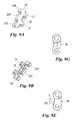
- the distance between the two guide elements 17 of each of the different modules 8A-E is always the same, the internal distance D1 (see Figure 9D ) between these two elements being preferably 20.75 mm and the external distance D2 being 28 mm. According to the invention, these distances lie within the following ranges: D1 15-30 mm, D2 17-32 mm.
- the side walls 7A-B of said element are spaced apart by about 1 mm less than the aforesaid internal distance of the guide elements 9.
- each module comprises a load-carrying surface 8A-E, this term in the present context identifying the module upper part to be used for transporting products.
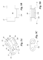
- each module 8A-E Three adjacent parts can be identified in each module 8A-E: a central part P1 ( Figure 9 ) having a width B1 ( Figure 9C ) substantially equal to the width C1 ( Figure 4B ) of the central element 7 of the support structure, and two lateral parts P2 and P3 having identical widths B2, these being external to said central part P1 and not being supported by said central element 7 when the conveyor slides thereon. It has been surprisingly found that by limiting the width B2 of the lateral parts P2 and P3 of the module load-carrying surface compared with the width B1 of their central part P1, a plurality of conveyors can be formed which are always supported by a single identical support structure.
- the width B2 of the unsupported lateral parts of the load-carrying surface must be between 0 and 3/2 the width B1 of the supported part P1 of the load-carrying surface (i.e. 0>B2>3/2B1) and that B1 must lie between 15 mm and 30 mm (i.e. 15mm>B1>30mm).
- each module comprises a connection system provided between the load-carrying surface 8A-E and the lower surface 18A-E, this connection system comprising on its front side 20 ( Figure 9C ), extending operationally transverse to the movement direction indicated by the arrow T, two spaced-apart connection elements 21 extending from said side.
- the module also comprises on the rear side 22, this also extending operationally transverse to the movement direction indicated by the arrow T, from one to three spaced-apart connection elements 23A, B extending from said side.
- the number of said elements depends on the module width.
- the rear central connection element 23A is wider than the front connection elements 21, the width W3 of the front central connection element 23A being for example about double the width W4 of the connection elements 21.
- the central connection element 23 the widest of the module, is provided at the part P1 of the load-carrying surface, i.e. that module part which is supported by the central support 7 of the conveyor support structure 5.
- connection elements 23A-B and 21 comprise a transverse through hole for passage of a connection pin (not shown).
- the module lower surface 18A-E is of conventional arcuate shape (in side view as in Figures 9 E-G ), it being centrally formed, as is usual to the expert of the art, such as to be able to cooperate ( Figure 9B ) with the teeth of a conventional drive wheel 6A of the mover element 6 of the conveyor support structure.
- the guide means could also be shaped and disposed such as to penetrate into one or more longitudinal cavities provided in said central support element.
- the support structures comprise, at one end of the central element 7, a bar or nosepiece 30 removably secured to conventional support means 31 provided for this purpose.
- the nosepiece 30 comprises an upper part 30A having a width C2 identical to that of the adjacent central element 7, resting on a lower part 30B of greater length C3 and forming with said upper part a step 30C on the two sides of the nosepiece 30.
- This lower part 30B is adapted to receive the guide elements 17 projecting from the module base.
- specific nosepieces can be provided presenting a resting surface having a width substantially equal to that of the module lower surface and two longitudinal grooves for passage of the guide elements 17.
- FIG. 1 show a support structure having a straight form in combination with conveyors and modules dedicated to this particular type of layout, the invention however also relating to a central support element having a curved form and a mixed curved and straight form, and modules shaped such as to be able to follow this type of form (i.e. side flexing modules).
- the support structure and the side flexing modules would have the same inventive characteristics as aforedescribed.
Landscapes
- Engineering & Computer Science (AREA)
- Mechanical Engineering (AREA)
- Chain Conveyers (AREA)
- Framework For Endless Conveyors (AREA)
- Structure Of Belt Conveyors (AREA)
Applications Claiming Priority (1)
| Application Number | Priority Date | Filing Date | Title |
|---|---|---|---|
| IT001389A ITMI20071389A1 (it) | 2007-07-12 | 2007-07-12 | Sistema di mini convogliatori |
Publications (1)
| Publication Number | Publication Date |
|---|---|
| EP2014585A2 true EP2014585A2 (de) | 2009-01-14 |
Family
ID=39842832
Family Applications (1)
| Application Number | Title | Priority Date | Filing Date |
|---|---|---|---|
| EP08157912A Withdrawn EP2014585A2 (de) | 2007-07-12 | 2008-06-10 | Mini-Fördersystem |
Country Status (4)
| Country | Link |
|---|---|
| US (1) | US20090014287A1 (de) |
| EP (1) | EP2014585A2 (de) |
| CA (1) | CA2635277A1 (de) |
| IT (1) | ITMI20071389A1 (de) |
Cited By (3)
| Publication number | Priority date | Publication date | Assignee | Title |
|---|---|---|---|---|
| EP2653411A1 (de) * | 2012-04-18 | 2013-10-23 | Tsubakimoto Chain Co. | Förderband |
| EP2640651A4 (de) * | 2010-11-19 | 2015-07-15 | Ramsey Products Corp | Multifunktionale integrierte verbindungsglieder für gliederkettenförderer und verfahren dafür |
| IT202100001676A1 (it) * | 2021-01-28 | 2022-07-28 | Movex S P A | Apparecchiatura motorizzata di trasferimento per trasportatori di oggetti in massa |
Families Citing this family (1)
| Publication number | Priority date | Publication date | Assignee | Title |
|---|---|---|---|---|
| AU2013305471C1 (en) * | 2012-08-22 | 2018-08-23 | Newsouth Innovations Pty Ltd | A method of forming a contact for a photovoltaic cell |
Family Cites Families (3)
| Publication number | Priority date | Publication date | Assignee | Title |
|---|---|---|---|---|
| US4418817A (en) * | 1981-07-17 | 1983-12-06 | Rexnord Inc. | Conveyor chain having carrier rollers |
| DE3228341A1 (de) * | 1981-10-23 | 1983-05-05 | Dietmar 6454 Bruchköbel Siebertz | Verfahren zum belegen von spielbaellen mit deckteilen |
| US6202834B1 (en) * | 1998-03-03 | 2001-03-20 | Span Tech Llc | Modular link conveyor with I-beam guide rail |
-
2007
- 2007-07-12 IT IT001389A patent/ITMI20071389A1/it unknown
-
2008
- 2008-06-10 EP EP08157912A patent/EP2014585A2/de not_active Withdrawn
- 2008-06-18 CA CA002635277A patent/CA2635277A1/en not_active Abandoned
- 2008-07-11 US US12/171,354 patent/US20090014287A1/en not_active Abandoned
Cited By (7)
| Publication number | Priority date | Publication date | Assignee | Title |
|---|---|---|---|---|
| EP2640651A4 (de) * | 2010-11-19 | 2015-07-15 | Ramsey Products Corp | Multifunktionale integrierte verbindungsglieder für gliederkettenförderer und verfahren dafür |
| EP2640651B1 (de) | 2010-11-19 | 2017-08-02 | Ramsey Products Corporation | Multifunktionale integrierte verbindungsglieder für gliederkettenförderer und verfahren dafür |
| EP2653411A1 (de) * | 2012-04-18 | 2013-10-23 | Tsubakimoto Chain Co. | Förderband |
| US9073694B2 (en) | 2012-04-18 | 2015-07-07 | Tsubakimoto Chain Co. | Conveyor belt |
| IT202100001676A1 (it) * | 2021-01-28 | 2022-07-28 | Movex S P A | Apparecchiatura motorizzata di trasferimento per trasportatori di oggetti in massa |
| EP4036038A1 (de) * | 2021-01-28 | 2022-08-03 | Movex S.p.A. | Motorisierte transfervorrichtung für förderer von schüttgut |
| US11685612B2 (en) | 2021-01-28 | 2023-06-27 | Movex S.P.A. | Motorized transfer apparatus for conveyors of bulk objects |
Also Published As
| Publication number | Publication date |
|---|---|
| ITMI20071389A1 (it) | 2009-01-13 |
| CA2635277A1 (en) | 2009-01-12 |
| US20090014287A1 (en) | 2009-01-15 |
Similar Documents
| Publication | Publication Date | Title |
|---|---|---|
| US9085414B2 (en) | Side-flexing conveyors | |
| US8235850B2 (en) | Multiple sprocket assembly | |
| EP0931736B1 (de) | Förderband mit seitlicher Faltung | |
| EP2176144B1 (de) | Modul mit grossem, offenem gelenk zur leichten reinigung | |
| EP2014585A2 (de) | Mini-Fördersystem | |
| US8770379B2 (en) | Sorting device | |
| EP1932781B1 (de) | Modulare Gurtverbindung mit abnehmbar befestigter Verstärkungsverbindung | |
| DK1655242T3 (da) | Sideböjende transportbånd | |
| US6918486B2 (en) | Conveyor chain | |
| CN101855151A (zh) | 扁钢丝传送带系统 | |
| AU747740B2 (en) | Conveyor mat | |
| PL1980504T3 (pl) | Modułowy przenośnik taśmowy z tworzywa sztucznego z wysoką wytrzymałością belki | |
| WO2000001599A1 (en) | Tapered side support for conveyor belts | |
| NL1034297C2 (nl) | Uit modules opgebouwde transportband en module. | |
| ES2393863A1 (es) | Transportador de rodillos modular para mover bultos. | |
| US5383547A (en) | Scraper conveyor | |
| KR20220008781A (ko) | 롤러 수송 표면을 구비하는 모듈식 컨베이어 벨트의 모듈 및 복수 개의 상기 모듈들에 의해 형성된 모듈식 컨베이어 벨트 | |
| DK181741B1 (en) | Glide strips and glide blocks for conveyors | |
| WO2008020755A2 (en) | Chain module for a modular chain conveyor, modular conveyor and conveying system provided with a modular chain conveyor | |
| CN2639253Y (zh) | 刮板输送机多销排座式中部槽 | |
| WO2011034419A1 (en) | Conveying system | |
| US20060175181A1 (en) | Reduced friction roller support for modular link conveyor chain | |
| EP4626814A1 (de) | Modulares förderband mit stückgutbewegungsmitteln | |
| JP3800543B2 (ja) | 印刷物搬送装置 | |
| KR100975879B1 (ko) | 금속 폐기물 컨베이어용 링크판 |
Legal Events
| Date | Code | Title | Description |
|---|---|---|---|
| PUAI | Public reference made under article 153(3) epc to a published international application that has entered the european phase |
Free format text: ORIGINAL CODE: 0009012 |
|
| AK | Designated contracting states |
Kind code of ref document: A2 Designated state(s): AT BE BG CH CY CZ DE DK EE ES FI FR GB GR HR HU IE IS IT LI LT LU LV MC MT NL NO PL PT RO SE SI SK TR |
|
| AX | Request for extension of the european patent |
Extension state: AL BA MK RS |
|
| RAP1 | Party data changed (applicant data changed or rights of an application transferred) |
Owner name: SYSTEM PLAST S.R.L. |
|
| STAA | Information on the status of an ep patent application or granted ep patent |
Free format text: STATUS: THE APPLICATION IS DEEMED TO BE WITHDRAWN |
|
| 18D | Application deemed to be withdrawn |
Effective date: 20110103 |