EP2014586B1 - Dispositif pour le transport de produits en vrac - Google Patents
Dispositif pour le transport de produits en vrac Download PDFInfo
- Publication number
- EP2014586B1 EP2014586B1 EP08158169A EP08158169A EP2014586B1 EP 2014586 B1 EP2014586 B1 EP 2014586B1 EP 08158169 A EP08158169 A EP 08158169A EP 08158169 A EP08158169 A EP 08158169A EP 2014586 B1 EP2014586 B1 EP 2014586B1
- Authority
- EP
- European Patent Office
- Prior art keywords
- screw feeder
- shaft
- fan
- containment tube
- sealing elements
- Prior art date
- Legal status (The legal status is an assumption and is not a legal conclusion. Google has not performed a legal analysis and makes no representation as to the accuracy of the status listed.)
- Ceased
Links
- 238000007789 sealing Methods 0.000 claims abstract description 23
- 230000009467 reduction Effects 0.000 claims description 9
- 210000003027 ear inner Anatomy 0.000 description 5
- 230000000694 effects Effects 0.000 description 3
- 230000000670 limiting effect Effects 0.000 description 2
- 238000012423 maintenance Methods 0.000 description 2
- 238000010521 absorption reaction Methods 0.000 description 1
- 239000003831 antifriction material Substances 0.000 description 1
- 230000009286 beneficial effect Effects 0.000 description 1
- 238000011109 contamination Methods 0.000 description 1
- 239000007789 gas Substances 0.000 description 1
- 230000005484 gravity Effects 0.000 description 1
- 239000004519 grease Substances 0.000 description 1
- 239000011261 inert gas Substances 0.000 description 1
- 238000002347 injection Methods 0.000 description 1
- 239000007924 injection Substances 0.000 description 1
- 239000000463 material Substances 0.000 description 1
- 238000012986 modification Methods 0.000 description 1
- 230000004048 modification Effects 0.000 description 1
- 238000012856 packing Methods 0.000 description 1
- 239000000843 powder Substances 0.000 description 1
- 238000004321 preservation Methods 0.000 description 1
Images


Classifications
-
- B—PERFORMING OPERATIONS; TRANSPORTING
- B65—CONVEYING; PACKING; STORING; HANDLING THIN OR FILAMENTARY MATERIAL
- B65G—TRANSPORT OR STORAGE DEVICES, e.g. CONVEYORS FOR LOADING OR TIPPING, SHOP CONVEYOR SYSTEMS OR PNEUMATIC TUBE CONVEYORS
- B65G33/00—Screw or rotary spiral conveyors
- B65G33/24—Details
- B65G33/32—Adaptations of bearings or couplings for supporting and connecting screws
-
- B—PERFORMING OPERATIONS; TRANSPORTING
- B65—CONVEYING; PACKING; STORING; HANDLING THIN OR FILAMENTARY MATERIAL
- B65G—TRANSPORT OR STORAGE DEVICES, e.g. CONVEYORS FOR LOADING OR TIPPING, SHOP CONVEYOR SYSTEMS OR PNEUMATIC TUBE CONVEYORS
- B65G33/00—Screw or rotary spiral conveyors
- B65G33/08—Screw or rotary spiral conveyors for fluent solid materials
- B65G33/14—Screw or rotary spiral conveyors for fluent solid materials comprising a screw or screws enclosed in a tubular housing
Definitions
- the present invention relates to a device for conveying loose products.
- devices for conveying loose products in granular or powder form comprising a ducted screw feeder which has, at one end, an actuation assembly and at least one support associated with a tube that contains such screw feeder, is known.
- a support at the opposite end with respect to the actuation assembly is always present, and for screw feeders of a certain length there is also an intermediate support to avoid excessive flexing of the shaft of the screw feeder.
- sealing elements which prevent the passage of the conveyed products, which would have extremely damaging consequences: accordingly, sealing elements of the most different types have been proposed which it is not appropriate to examine in detail here (see US-A-3 896 923 , for example), such as for example labyrinth seals, or seals pressurized with a pneumatic line, or grease seals, all of which are not devoid of disadvantageous characteristics linked to constructive complexities, great need for maintenance, and the possibility of contamination of the conveyed products.
- the aim of the present invention is to provide a conveyor of the type that comprises a ducted screw feeder which has maximum functional efficiency in treating the conveyed loose products and in which particular attention is paid to the effectiveness and preservation of the sealing elements.
- the reference numeral 1 generally designates a screw feeder, which comprises a shaft 2 for supporting a screw 3, which is contained within a containment tube 4 provided with flanges 4a, 4b at its ends; the reference numerals 5 and 6 designate respectively a loading port and a discharge port of the conveyed loose products.
- the screw feeder 1 has, at one end, an actuation assembly, generally designated by the reference numeral 7, which is described in detail with reference to Figure 2 , and further has an intermediate support, generally designated by the reference numeral 8, and an end support, generally designated by the reference numeral 9, which will be described in detail with reference to Figures 3 and 4 respectively.
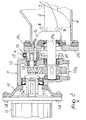
- the actuation assembly 7 first of all comprises a gear-type reduction unit contained in a casing 10, which is connected, by means of screws 11, to a flange 12 for connection to an electric motor 13, to which such flange is fixed by means of bolts 14; the reference numeral 10a designates a cover for closing the casing 10.
- a high-speed shaft 15 of the reduction unit is connected to an output shaft 13a of the electric motor 13 and a low-speed shaft of said reduction unit is constituted by a terminal 2a associated with the shaft 2 of the screw feeder, which is provided with sealing elements of the mechanical type, such as for example packings and labyrinths, comprised within a body 16, which are adapted to prevent the escape of the loose products from the containment tube 4.
- a fan 17 is keyed to the high-speed shaft 15 of the reduction unit and is comprised within a seat provided within the casing 10 and aspirates atmospheric air by means of a perforated screw 18 provided with a filter, along the arrow A, and sends it into a channel 19 which is formed partly within a flange 20 which is fixed to the casing 10 by means of screws 21 and partly in the body 16 that accommodates the sealing elements; attention is called to the particular contour of the flange 20, which allows the evacuation by gravity of any product that has escaped the sealing elements comprised within the body 16.
- the air in output from the fan enters, by following the arrows in Figure 2 , the channel 19 to exit, by passing at least partly through the sealing elements comprised within the body 16, within the screw feeder containment tube 4, as indicated by the arrows B.
- the intermediate support 8 is now described in detail and comprises a body made of antifriction material which is formed by an upper half-shell 8a, which is associated with the tube 4 for containing the screw feeder, and by a lower half-shell 8b, which is connected to the half-shell 8a by means of bolts 22; moreover, labyrinth seals in contact with a portion 2b of the shaft 2 of the screw feeder comprised within the support are designated by the reference numeral 23.
- a fan 24 is keyed to the portion 2b and receives atmospheric air, which has entered along the arrow C through a perforated screw with filter 25 and has been fed to the fan by a duct 26, in order to send it so that it passes through the labyrinth seals 23 and enters along the arrows D the tube 4, thus achieving the beneficial effects described earlier with reference to the air introduced in the screw feeder at the actuation assembly.
- Figure 4 is a detailed view of the support 9 of the terminal 2c associated with the shaft 2, which comprises a body 9a, which is closed by a cover 9b and is associated with the flange 4b of the containment tube 4 of the screw feeder by means of bolts 9c.
- a fan 27 is keyed to the terminal 2c of the shaft 2 and receives atmospheric air which has entered a duct 28 through a perforated screw with filter 29 according to the arrow E, and sends it so that it passes through the labyrinth seal 30 to enter the tube 4 along the arrows F; it is hardly necessary to mention once again the advantages achieved by such introduction of air into the screw feeder.
- connection between the fan comprised within the actuation assembly and the corresponding seals can be obtained in any manner, by adopting for example a separate duct which is optionally provided by means of a flexible tube.
- shape of the cross-section of the screw feeder containment tube may be any.
Landscapes
- Engineering & Computer Science (AREA)
- Mechanical Engineering (AREA)
- Screw Conveyors (AREA)
- Air Transport Of Granular Materials (AREA)
- Container Filling Or Packaging Operations (AREA)
Claims (8)
- Dispositif pour convoyer des produits en vrac, comprenant un extracteur à vis (1) dans un conduit, qui comporte, à une extrémité, un ensemble d'actionnement (7), qui comprend des éléments pour amener les produits convoyés en contact étanche avec l'arbre (2) dudit extracteur à vis (1), et qui est de plus muni d'au moins un support (8, 9) qui est associé à un tube de confinement (4) en présence d'éléments d'étanchéité, caractérisé en ce qu'il comprend des moyens (17) qui utilisent l'énergie d'un moteur (13) inclus à l'intérieur dudit ensemble d'actionnement (7) et qui sont adaptés pour aspirer de l'air atmosphérique afin de l'envoyer dans ledit tube de confinement (4), traversant au moins partiellement lesdits éléments d'étanchéité en contact avec l'arbre (2) de l'extracteur à vis.
- Dispositif selon la revendication 1, caractérisé en ce que lesdits moyens qui utilisent l'énergie du moteur (13) comprennent un ventilateur (17) qui est inclus à l'intérieur de l'ensemble d'actionnement (7), qui est motorisé par celui-ci et qui est adapté pour aspirer de l'air atmosphérique afin de l'envoyer à l'intérieur du tube de confinement de l'extracteur à vis (4) en traversant au moins partiellement les éléments d'étanchéité du produit convoyé en contact avec l'arbre dudit extracteur à vis.
- Dispositif selon les revendication 1 et 2, caractérisé en ce que ledit extracteur à vis (1) est un extracteur à vis dans un conduit, qui comporte, à une extrémité, ledit ensemble d'actionnement, qui comprend une unité réductrice du type à engrenages avec un arbre d'entrée à haute vitesse (15) relié audit moteur (13) et un arbre de sortie à basse vitesse (2a) associé à l'arbre de l'extracteur à vis, ledit ventilateur (17) étant fixé sur ledit arbre à haute vitesse (15), un canal (19) étant disposé, à l'intérieur de l'ensemble d'actionnement, pour délivrer l'air en sortie du ventilateur à l'intérieur du tube de confinement de l'extracteur à vis, traversant au moins partiellement les éléments d'étanchéité en contact avec ledit arbre à basse vitesse.
- Dispositif selon la revendication 3, caractérisé en ce que le ventilateur (17) fixé sur l'arbre à haute vitesse (15) de l'unité réductrice est reçu à l'intérieur du carter (10) de ladite unité réductrice, tandis que le canal (19) pour délivrer de l'air en sortie du ventilateur vers le tube de confinement de l'extracteur à vis est disposé, dans une partie initiale, dans un flasque (20) qui est interposé entre ledit carter (10) et ledit tube (4), et, en ce qui concerne la partie d'extrémité, dans un corps pour contenir les éléments d'étanchéité.
- Dispositif selon la revendication 1, caractérisé en ce que ledit support au nombre d'au moins un comprend un support intermédiaire (8) de l'arbre (2) de l'extracteur à vis qui est associé au tube qui contient ledit extracteur à vis et est muni desdits éléments d'étanchéité du produit convoyé en contact avec ledit arbre, lesdits moyens qui utilisent l'énergie du moteur étant un ventilateur fixé sur la partie d'arbre qui est incluse à l'intérieur du support et qui est adapté pour recevoir de l'air atmosphérique afin de l'envoyer à l'intérieur du tube de confinement de l'extracteur à vis, traversant au moins partiellement lesdits éléments d'étanchéité.
- Dispositif selon la revendication 1, caractérisé en ce que ledit support au nombre d'au moins un comprend un support d'extrémité (9) de l'arbre de l'extracteur à vis qui est associé au tube de confinement dudit extracteur à vis et qui est muni desdits éléments d'étanchéité du produit convoyé en contact avec ledit arbre, lesdits moyens qui utilisent l'énergie du moteur étant un ventilateur qui est fixé à l'extrémité de l'arbre qui est inclus l'intérieur du support et qui est adapté pour recevoir de l'air atmosphérique afin de l'envoyer à l'intérieur du tube de confinement de l'extracteur à vis, traversant au moins partiellement lesdits éléments d'étanchéité.
- Dispositif selon l'une ou plusieurs des revendications précédentes, caractérisé en ce que le conduit pour convoyer l'air atmosphérique vers le ventilateur comporte, à l'orifice d'entrée, une vis perforée (18) munie d'un filtre (A).
- Dispositif selon l'une ou plusieurs des revendications précédentes, caractérisé en ce qu'il comprend des moyens pour injecter un gaz qui est convoyé par une ligne sous pression à l'intérieur du tube de confinement de l'extracteur à vis (4).
Applications Claiming Priority (1)
| Application Number | Priority Date | Filing Date | Title |
|---|---|---|---|
| IT000033A ITMN20070033A1 (it) | 2007-07-09 | 2007-07-09 | Dispositivo di trasporto di prodotti sfusi |
Publications (2)
| Publication Number | Publication Date |
|---|---|
| EP2014586A1 EP2014586A1 (fr) | 2009-01-14 |
| EP2014586B1 true EP2014586B1 (fr) | 2010-03-10 |
Family
ID=39767224
Family Applications (1)
| Application Number | Title | Priority Date | Filing Date |
|---|---|---|---|
| EP08158169A Ceased EP2014586B1 (fr) | 2007-07-09 | 2008-06-12 | Dispositif pour le transport de produits en vrac |
Country Status (4)
| Country | Link |
|---|---|
| EP (1) | EP2014586B1 (fr) |
| AT (1) | ATE460365T1 (fr) |
| DE (1) | DE602008000778D1 (fr) |
| IT (1) | ITMN20070033A1 (fr) |
Families Citing this family (2)
| Publication number | Priority date | Publication date | Assignee | Title |
|---|---|---|---|---|
| CN106051166B (zh) * | 2016-07-26 | 2017-09-05 | 马鞍山市方正机械制造有限责任公司 | 一种水冲渣搅笼机水下轴承及其密封装置 |
| CN106586423A (zh) * | 2016-11-24 | 2017-04-26 | 蓬溪斌鹏科技有限公司 | 一种用于螺旋输送机轴头的密封装置 |
Family Cites Families (3)
| Publication number | Priority date | Publication date | Assignee | Title |
|---|---|---|---|---|
| US3896923A (en) * | 1974-02-06 | 1975-07-29 | Continental Oil Co | Screw feeder |
| DE10250746A1 (de) * | 2002-10-31 | 2004-05-13 | Schenck Process Gmbh | Wellendurchführung |
| US20050184103A1 (en) * | 2003-12-19 | 2005-08-25 | Giuseppe Palma | Loss-in-weight feeder for powders and dry goods |
-
2007
- 2007-07-09 IT IT000033A patent/ITMN20070033A1/it unknown
-
2008
- 2008-06-12 EP EP08158169A patent/EP2014586B1/fr not_active Ceased
- 2008-06-12 AT AT08158169T patent/ATE460365T1/de not_active IP Right Cessation
- 2008-06-12 DE DE602008000778T patent/DE602008000778D1/de active Active
Also Published As
| Publication number | Publication date |
|---|---|
| DE602008000778D1 (de) | 2010-04-22 |
| EP2014586A1 (fr) | 2009-01-14 |
| ITMN20070033A1 (it) | 2009-01-10 |
| ATE460365T1 (de) | 2010-03-15 |
Similar Documents
| Publication | Publication Date | Title |
|---|---|---|
| WO2009009189A2 (fr) | Transport de matière particulaire | |
| EP2014586B1 (fr) | Dispositif pour le transport de produits en vrac | |
| JPH06221292A (ja) | 粒状固体用ポンプ | |
| EP1818111A3 (fr) | Dispositif et installation de suppression de poussière pour les matériaux granuleux | |
| JP2011234717A (ja) | タバコ加工産業における棒状製品をマガジンから搬送路へ搬送する搬送装置及び搬送方法 | |
| US8522449B2 (en) | Dryer for fuel material | |
| CN104495253A (zh) | 一种双向双头螺旋输送机 | |
| KR20190018006A (ko) | 백 프레스 공급기 조립체 | |
| ZA202006993B (en) | Aero-acoustic materials processing plant with noise attenuation system | |
| CA2727805A1 (fr) | Dispositif d'impregnation d'un materiau fibreux a l'aide d'un liquide | |
| US9604794B2 (en) | Apparatus for handling fine bulk material | |
| CN106986190B (zh) | 密封性关风器 | |
| US4558985A (en) | Pump with screw conveyors on each end | |
| CN114906622B (zh) | 电磁与先导气联合的自适应密封的旋转给料器 | |
| US2559616A (en) | Pressure-sealing apparatus for flight conveyers | |
| CN108438959A (zh) | 一种皮带运输转载点产尘及降尘实验系统 | |
| US6293439B1 (en) | High pressure valve | |
| US20170009023A1 (en) | Process for the processing of an undried, particulate polymer or polymer mixture by means of a single- or multiscrew extruder | |
| CN211569169U (zh) | 星型加料器 | |
| MXPA05013005A (es) | Soplador de un solo motor mejorado. | |
| CN207826667U (zh) | 一种化学实验防毒面罩的快速包装装置 | |
| US20260070747A1 (en) | Conveying and drying systems for granulated materials | |
| CN201548026U (zh) | 矿粉处理专用烘干机 | |
| CN215831180U (zh) | 一种闸阀门密封结构 | |
| JP2000128348A (ja) | ロータリー搬送装置 |
Legal Events
| Date | Code | Title | Description |
|---|---|---|---|
| PUAI | Public reference made under article 153(3) epc to a published international application that has entered the european phase |
Free format text: ORIGINAL CODE: 0009012 |
|
| AK | Designated contracting states |
Kind code of ref document: A1 Designated state(s): AT BE BG CH CY CZ DE DK EE ES FI FR GB GR HR HU IE IS IT LI LT LU LV MC MT NL NO PL PT RO SE SI SK TR |
|
| AX | Request for extension of the european patent |
Extension state: AL BA MK RS |
|
| 17P | Request for examination filed |
Effective date: 20090714 |
|
| GRAP | Despatch of communication of intention to grant a patent |
Free format text: ORIGINAL CODE: EPIDOSNIGR1 |
|
| AKX | Designation fees paid |
Designated state(s): AT BE BG CH CY CZ DE DK EE ES FI FR GB GR HR HU IE IS IT LI LT LU LV MC MT NL NO PL PT RO SE SI SK TR |
|
| GRAS | Grant fee paid |
Free format text: ORIGINAL CODE: EPIDOSNIGR3 |
|
| GRAA | (expected) grant |
Free format text: ORIGINAL CODE: 0009210 |
|
| AK | Designated contracting states |
Kind code of ref document: B1 Designated state(s): AT BE BG CH CY CZ DE DK EE ES FI FR GB GR HR HU IE IS IT LI LT LU LV MC MT NL NO PL PT RO SE SI SK TR |
|
| REG | Reference to a national code |
Ref country code: GB Ref legal event code: FG4D |
|
| REG | Reference to a national code |
Ref country code: CH Ref legal event code: EP |
|
| REG | Reference to a national code |
Ref country code: IE Ref legal event code: FG4D |
|
| REF | Corresponds to: |
Ref document number: 602008000778 Country of ref document: DE Date of ref document: 20100422 Kind code of ref document: P |
|
| REG | Reference to a national code |
Ref country code: NL Ref legal event code: VDEP Effective date: 20100310 |
|
| PG25 | Lapsed in a contracting state [announced via postgrant information from national office to epo] |
Ref country code: NO Free format text: LAPSE BECAUSE OF FAILURE TO SUBMIT A TRANSLATION OF THE DESCRIPTION OR TO PAY THE FEE WITHIN THE PRESCRIBED TIME-LIMIT Effective date: 20100610 Ref country code: HR Free format text: LAPSE BECAUSE OF FAILURE TO SUBMIT A TRANSLATION OF THE DESCRIPTION OR TO PAY THE FEE WITHIN THE PRESCRIBED TIME-LIMIT Effective date: 20100310 Ref country code: LT Free format text: LAPSE BECAUSE OF FAILURE TO SUBMIT A TRANSLATION OF THE DESCRIPTION OR TO PAY THE FEE WITHIN THE PRESCRIBED TIME-LIMIT Effective date: 20100310 |
|
| LTIE | Lt: invalidation of european patent or patent extension |
Effective date: 20100310 |
|
| PG25 | Lapsed in a contracting state [announced via postgrant information from national office to epo] |
Ref country code: AT Free format text: LAPSE BECAUSE OF FAILURE TO SUBMIT A TRANSLATION OF THE DESCRIPTION OR TO PAY THE FEE WITHIN THE PRESCRIBED TIME-LIMIT Effective date: 20100310 Ref country code: FI Free format text: LAPSE BECAUSE OF FAILURE TO SUBMIT A TRANSLATION OF THE DESCRIPTION OR TO PAY THE FEE WITHIN THE PRESCRIBED TIME-LIMIT Effective date: 20100310 Ref country code: LV Free format text: LAPSE BECAUSE OF FAILURE TO SUBMIT A TRANSLATION OF THE DESCRIPTION OR TO PAY THE FEE WITHIN THE PRESCRIBED TIME-LIMIT Effective date: 20100310 Ref country code: PL Free format text: LAPSE BECAUSE OF FAILURE TO SUBMIT A TRANSLATION OF THE DESCRIPTION OR TO PAY THE FEE WITHIN THE PRESCRIBED TIME-LIMIT Effective date: 20100310 Ref country code: SI Free format text: LAPSE BECAUSE OF FAILURE TO SUBMIT A TRANSLATION OF THE DESCRIPTION OR TO PAY THE FEE WITHIN THE PRESCRIBED TIME-LIMIT Effective date: 20100310 |
|
| PG25 | Lapsed in a contracting state [announced via postgrant information from national office to epo] |
Ref country code: BE Free format text: LAPSE BECAUSE OF FAILURE TO SUBMIT A TRANSLATION OF THE DESCRIPTION OR TO PAY THE FEE WITHIN THE PRESCRIBED TIME-LIMIT Effective date: 20100310 Ref country code: SE Free format text: LAPSE BECAUSE OF FAILURE TO SUBMIT A TRANSLATION OF THE DESCRIPTION OR TO PAY THE FEE WITHIN THE PRESCRIBED TIME-LIMIT Effective date: 20100310 Ref country code: RO Free format text: LAPSE BECAUSE OF FAILURE TO SUBMIT A TRANSLATION OF THE DESCRIPTION OR TO PAY THE FEE WITHIN THE PRESCRIBED TIME-LIMIT Effective date: 20100310 Ref country code: NL Free format text: LAPSE BECAUSE OF FAILURE TO SUBMIT A TRANSLATION OF THE DESCRIPTION OR TO PAY THE FEE WITHIN THE PRESCRIBED TIME-LIMIT Effective date: 20100310 Ref country code: CY Free format text: LAPSE BECAUSE OF FAILURE TO SUBMIT A TRANSLATION OF THE DESCRIPTION OR TO PAY THE FEE WITHIN THE PRESCRIBED TIME-LIMIT Effective date: 20100310 Ref country code: EE Free format text: LAPSE BECAUSE OF FAILURE TO SUBMIT A TRANSLATION OF THE DESCRIPTION OR TO PAY THE FEE WITHIN THE PRESCRIBED TIME-LIMIT Effective date: 20100310 Ref country code: ES Free format text: LAPSE BECAUSE OF FAILURE TO SUBMIT A TRANSLATION OF THE DESCRIPTION OR TO PAY THE FEE WITHIN THE PRESCRIBED TIME-LIMIT Effective date: 20100621 Ref country code: GR Free format text: LAPSE BECAUSE OF FAILURE TO SUBMIT A TRANSLATION OF THE DESCRIPTION OR TO PAY THE FEE WITHIN THE PRESCRIBED TIME-LIMIT Effective date: 20100611 |
|
| PG25 | Lapsed in a contracting state [announced via postgrant information from national office to epo] |
Ref country code: CZ Free format text: LAPSE BECAUSE OF FAILURE TO SUBMIT A TRANSLATION OF THE DESCRIPTION OR TO PAY THE FEE WITHIN THE PRESCRIBED TIME-LIMIT Effective date: 20100310 Ref country code: SK Free format text: LAPSE BECAUSE OF FAILURE TO SUBMIT A TRANSLATION OF THE DESCRIPTION OR TO PAY THE FEE WITHIN THE PRESCRIBED TIME-LIMIT Effective date: 20100310 Ref country code: IS Free format text: LAPSE BECAUSE OF FAILURE TO SUBMIT A TRANSLATION OF THE DESCRIPTION OR TO PAY THE FEE WITHIN THE PRESCRIBED TIME-LIMIT Effective date: 20100710 Ref country code: BG Free format text: LAPSE BECAUSE OF FAILURE TO SUBMIT A TRANSLATION OF THE DESCRIPTION OR TO PAY THE FEE WITHIN THE PRESCRIBED TIME-LIMIT Effective date: 20100610 |
|
| PLBE | No opposition filed within time limit |
Free format text: ORIGINAL CODE: 0009261 |
|
| STAA | Information on the status of an ep patent application or granted ep patent |
Free format text: STATUS: NO OPPOSITION FILED WITHIN TIME LIMIT |
|
| PG25 | Lapsed in a contracting state [announced via postgrant information from national office to epo] |
Ref country code: MC Free format text: LAPSE BECAUSE OF NON-PAYMENT OF DUE FEES Effective date: 20100630 Ref country code: DK Free format text: LAPSE BECAUSE OF FAILURE TO SUBMIT A TRANSLATION OF THE DESCRIPTION OR TO PAY THE FEE WITHIN THE PRESCRIBED TIME-LIMIT Effective date: 20100310 |
|
| 26N | No opposition filed |
Effective date: 20101213 |
|
| PG25 | Lapsed in a contracting state [announced via postgrant information from national office to epo] |
Ref country code: IE Free format text: LAPSE BECAUSE OF NON-PAYMENT OF DUE FEES Effective date: 20100612 Ref country code: MT Free format text: LAPSE BECAUSE OF FAILURE TO SUBMIT A TRANSLATION OF THE DESCRIPTION OR TO PAY THE FEE WITHIN THE PRESCRIBED TIME-LIMIT Effective date: 20100310 |
|
| PGFP | Annual fee paid to national office [announced via postgrant information from national office to epo] |
Ref country code: IT Payment date: 20110630 Year of fee payment: 4 |
|
| PG25 | Lapsed in a contracting state [announced via postgrant information from national office to epo] |
Ref country code: PT Free format text: LAPSE BECAUSE OF FAILURE TO SUBMIT A TRANSLATION OF THE DESCRIPTION OR TO PAY THE FEE WITHIN THE PRESCRIBED TIME-LIMIT Effective date: 20100810 Ref country code: LU Free format text: LAPSE BECAUSE OF NON-PAYMENT OF DUE FEES Effective date: 20100612 Ref country code: HU Free format text: LAPSE BECAUSE OF FAILURE TO SUBMIT A TRANSLATION OF THE DESCRIPTION OR TO PAY THE FEE WITHIN THE PRESCRIBED TIME-LIMIT Effective date: 20100911 |
|
| REG | Reference to a national code |
Ref country code: CH Ref legal event code: PL |
|
| REG | Reference to a national code |
Ref country code: CH Ref legal event code: PL |
|
| PG25 | Lapsed in a contracting state [announced via postgrant information from national office to epo] |
Ref country code: IT Free format text: LAPSE BECAUSE OF NON-PAYMENT OF DUE FEES Effective date: 20120612 |
|
| PG25 | Lapsed in a contracting state [announced via postgrant information from national office to epo] |
Ref country code: CH Free format text: LAPSE BECAUSE OF NON-PAYMENT OF DUE FEES Effective date: 20120630 Ref country code: LI Free format text: LAPSE BECAUSE OF NON-PAYMENT OF DUE FEES Effective date: 20120630 |
|
| REG | Reference to a national code |
Ref country code: FR Ref legal event code: PLFP Year of fee payment: 8 |
|
| REG | Reference to a national code |
Ref country code: FR Ref legal event code: PLFP Year of fee payment: 9 |
|
| PGFP | Annual fee paid to national office [announced via postgrant information from national office to epo] |
Ref country code: GB Payment date: 20160629 Year of fee payment: 9 |
|
| PGFP | Annual fee paid to national office [announced via postgrant information from national office to epo] |
Ref country code: TR Payment date: 20160523 Year of fee payment: 9 |
|
| REG | Reference to a national code |
Ref country code: FR Ref legal event code: PLFP Year of fee payment: 10 |
|
| GBPC | Gb: european patent ceased through non-payment of renewal fee |
Effective date: 20170612 |
|
| PG25 | Lapsed in a contracting state [announced via postgrant information from national office to epo] |
Ref country code: GB Free format text: LAPSE BECAUSE OF NON-PAYMENT OF DUE FEES Effective date: 20170612 |
|
| REG | Reference to a national code |
Ref country code: FR Ref legal event code: PLFP Year of fee payment: 11 |
|
| PGFP | Annual fee paid to national office [announced via postgrant information from national office to epo] |
Ref country code: FR Payment date: 20200625 Year of fee payment: 13 Ref country code: DE Payment date: 20200625 Year of fee payment: 13 |
|
| REG | Reference to a national code |
Ref country code: DE Ref legal event code: R119 Ref document number: 602008000778 Country of ref document: DE |
|
| PG25 | Lapsed in a contracting state [announced via postgrant information from national office to epo] |
Ref country code: DE Free format text: LAPSE BECAUSE OF NON-PAYMENT OF DUE FEES Effective date: 20220101 |
|
| PG25 | Lapsed in a contracting state [announced via postgrant information from national office to epo] |
Ref country code: FR Free format text: LAPSE BECAUSE OF NON-PAYMENT OF DUE FEES Effective date: 20210630 |
|
| PG25 | Lapsed in a contracting state [announced via postgrant information from national office to epo] |
Ref country code: TR Free format text: LAPSE BECAUSE OF NON-PAYMENT OF DUE FEES Effective date: 20170612 |