EP2014630A2 - Appareil de cuisson et procédé pour la fabrication d'un corps à structure en nid d'abeille - Google Patents
Appareil de cuisson et procédé pour la fabrication d'un corps à structure en nid d'abeille Download PDFInfo
- Publication number
- EP2014630A2 EP2014630A2 EP08000971A EP08000971A EP2014630A2 EP 2014630 A2 EP2014630 A2 EP 2014630A2 EP 08000971 A EP08000971 A EP 08000971A EP 08000971 A EP08000971 A EP 08000971A EP 2014630 A2 EP2014630 A2 EP 2014630A2
- Authority
- EP
- European Patent Office
- Prior art keywords
- coat layer
- molded body
- honeycomb
- sic
- honeycomb molded
- Prior art date
- Legal status (The legal status is an assumption and is not a legal conclusion. Google has not performed a legal analysis and makes no representation as to the accuracy of the status listed.)
- Withdrawn
Links
- 238000010304 firing Methods 0.000 title claims abstract description 206
- 238000000034 method Methods 0.000 title claims description 92
- 238000004519 manufacturing process Methods 0.000 title claims description 58
- HBMJWWWQQXIZIP-UHFFFAOYSA-N silicon carbide Chemical compound [Si+]#[C-] HBMJWWWQQXIZIP-UHFFFAOYSA-N 0.000 claims abstract description 209
- 229910010271 silicon carbide Inorganic materials 0.000 claims abstract description 198
- 239000000463 material Substances 0.000 claims description 64
- 239000002245 particle Substances 0.000 claims description 58
- 239000000203 mixture Substances 0.000 claims description 41
- VYPSYNLAJGMNEJ-UHFFFAOYSA-N Silicium dioxide Chemical compound O=[Si]=O VYPSYNLAJGMNEJ-UHFFFAOYSA-N 0.000 claims description 40
- 238000000227 grinding Methods 0.000 claims description 34
- 210000004027 cell Anatomy 0.000 claims description 32
- 229910052799 carbon Inorganic materials 0.000 claims description 25
- 238000005238 degreasing Methods 0.000 claims description 23
- 239000000377 silicon dioxide Substances 0.000 claims description 20
- OKTJSMMVPCPJKN-UHFFFAOYSA-N Carbon Chemical compound [C] OKTJSMMVPCPJKN-UHFFFAOYSA-N 0.000 claims description 19
- 229910052681 coesite Inorganic materials 0.000 claims description 19
- 229910052906 cristobalite Inorganic materials 0.000 claims description 19
- 125000006850 spacer group Chemical group 0.000 claims description 19
- 229910052682 stishovite Inorganic materials 0.000 claims description 19
- 229910052905 tridymite Inorganic materials 0.000 claims description 19
- 239000012808 vapor phase Substances 0.000 claims description 17
- 239000000126 substance Substances 0.000 claims description 14
- 229910052710 silicon Inorganic materials 0.000 claims description 13
- 210000002421 cell wall Anatomy 0.000 claims description 12
- 229920000642 polymer Polymers 0.000 claims description 12
- 230000008595 infiltration Effects 0.000 claims description 11
- 238000001764 infiltration Methods 0.000 claims description 11
- 229920000673 poly(carbodihydridosilane) Polymers 0.000 claims description 8
- 229910010293 ceramic material Inorganic materials 0.000 claims description 5
- 238000000465 moulding Methods 0.000 claims description 2
- 206010040844 Skin exfoliation Diseases 0.000 abstract description 23
- 230000015572 biosynthetic process Effects 0.000 abstract description 10
- 239000010410 layer Substances 0.000 description 204
- 238000006243 chemical reaction Methods 0.000 description 42
- 230000003746 surface roughness Effects 0.000 description 33
- 238000011282 treatment Methods 0.000 description 29
- 239000011148 porous material Substances 0.000 description 22
- 238000005245 sintering Methods 0.000 description 22
- 230000000052 comparative effect Effects 0.000 description 20
- 239000003566 sealing material Substances 0.000 description 18
- 239000000919 ceramic Substances 0.000 description 16
- 238000001035 drying Methods 0.000 description 15
- 239000011230 binding agent Substances 0.000 description 14
- 239000000843 powder Substances 0.000 description 12
- 238000001953 recrystallisation Methods 0.000 description 11
- 238000005755 formation reaction Methods 0.000 description 10
- 239000007789 gas Substances 0.000 description 10
- 230000006641 stabilisation Effects 0.000 description 10
- 238000011105 stabilization Methods 0.000 description 10
- PNEYBMLMFCGWSK-UHFFFAOYSA-N aluminium oxide Inorganic materials [O-2].[O-2].[O-2].[Al+3].[Al+3] PNEYBMLMFCGWSK-UHFFFAOYSA-N 0.000 description 9
- 239000000470 constituent Substances 0.000 description 9
- 238000010438 heat treatment Methods 0.000 description 9
- 239000012298 atmosphere Substances 0.000 description 8
- -1 polypropylene Polymers 0.000 description 8
- OKKJLVBELUTLKV-UHFFFAOYSA-N Methanol Chemical compound OC OKKJLVBELUTLKV-UHFFFAOYSA-N 0.000 description 7
- XUIMIQQOPSSXEZ-UHFFFAOYSA-N Silicon Chemical compound [Si] XUIMIQQOPSSXEZ-UHFFFAOYSA-N 0.000 description 7
- 239000010703 silicon Substances 0.000 description 7
- UHOVQNZJYSORNB-UHFFFAOYSA-N Benzene Chemical compound C1=CC=CC=C1 UHOVQNZJYSORNB-UHFFFAOYSA-N 0.000 description 6
- 238000005229 chemical vapour deposition Methods 0.000 description 6
- 239000000835 fiber Substances 0.000 description 6
- 239000003054 catalyst Substances 0.000 description 5
- 238000011156 evaluation Methods 0.000 description 5
- 239000012535 impurity Substances 0.000 description 5
- 239000000314 lubricant Substances 0.000 description 5
- 229920000609 methyl cellulose Polymers 0.000 description 5
- 239000001923 methylcellulose Substances 0.000 description 5
- 235000010981 methylcellulose Nutrition 0.000 description 5
- 238000005507 spraying Methods 0.000 description 5
- 229920002134 Carboxymethyl cellulose Polymers 0.000 description 4
- PEDCQBHIVMGVHV-UHFFFAOYSA-N Glycerine Chemical compound OCC(O)CO PEDCQBHIVMGVHV-UHFFFAOYSA-N 0.000 description 4
- 239000006061 abrasive grain Substances 0.000 description 4
- 239000012300 argon atmosphere Substances 0.000 description 4
- 239000001768 carboxy methyl cellulose Substances 0.000 description 4
- 235000010948 carboxy methyl cellulose Nutrition 0.000 description 4
- 239000008112 carboxymethyl-cellulose Substances 0.000 description 4
- 238000000576 coating method Methods 0.000 description 4
- 229910003460 diamond Inorganic materials 0.000 description 4
- 239000010432 diamond Substances 0.000 description 4
- 238000001125 extrusion Methods 0.000 description 4
- 238000002156 mixing Methods 0.000 description 4
- 230000035882 stress Effects 0.000 description 4
- 230000008646 thermal stress Effects 0.000 description 4
- XLYOFNOQVPJJNP-UHFFFAOYSA-N water Substances O XLYOFNOQVPJJNP-UHFFFAOYSA-N 0.000 description 4
- LYCAIKOWRPUZTN-UHFFFAOYSA-N Ethylene glycol Chemical compound OCCO LYCAIKOWRPUZTN-UHFFFAOYSA-N 0.000 description 3
- 229910052581 Si3N4 Inorganic materials 0.000 description 3
- KZHJGOXRZJKJNY-UHFFFAOYSA-N dioxosilane;oxo(oxoalumanyloxy)alumane Chemical compound O=[Si]=O.O=[Si]=O.O=[Al]O[Al]=O.O=[Al]O[Al]=O.O=[Al]O[Al]=O KZHJGOXRZJKJNY-UHFFFAOYSA-N 0.000 description 3
- 239000004744 fabric Substances 0.000 description 3
- 230000002349 favourable effect Effects 0.000 description 3
- 239000012784 inorganic fiber Substances 0.000 description 3
- 239000010954 inorganic particle Substances 0.000 description 3
- 239000007788 liquid Substances 0.000 description 3
- 229910052863 mullite Inorganic materials 0.000 description 3
- 239000003960 organic solvent Substances 0.000 description 3
- 239000004014 plasticizer Substances 0.000 description 3
- 239000002994 raw material Substances 0.000 description 3
- 239000011347 resin Substances 0.000 description 3
- 229920005989 resin Polymers 0.000 description 3
- 238000007789 sealing Methods 0.000 description 3
- HQVNEWCFYHHQES-UHFFFAOYSA-N silicon nitride Chemical compound N12[Si]34N5[Si]62N3[Si]51N64 HQVNEWCFYHHQES-UHFFFAOYSA-N 0.000 description 3
- XKRFYHLGVUSROY-UHFFFAOYSA-N Argon Chemical compound [Ar] XKRFYHLGVUSROY-UHFFFAOYSA-N 0.000 description 2
- IJGRMHOSHXDMSA-UHFFFAOYSA-N Atomic nitrogen Chemical compound N#N IJGRMHOSHXDMSA-UHFFFAOYSA-N 0.000 description 2
- 229910052582 BN Inorganic materials 0.000 description 2
- PZNSFCLAULLKQX-UHFFFAOYSA-N Boron nitride Chemical compound N#B PZNSFCLAULLKQX-UHFFFAOYSA-N 0.000 description 2
- 229920000049 Carbon (fiber) Polymers 0.000 description 2
- 229920000663 Hydroxyethyl cellulose Polymers 0.000 description 2
- 239000004354 Hydroxyethyl cellulose Substances 0.000 description 2
- CPLXHLVBOLITMK-UHFFFAOYSA-N Magnesium oxide Chemical compound [Mg]=O CPLXHLVBOLITMK-UHFFFAOYSA-N 0.000 description 2
- 239000002202 Polyethylene glycol Substances 0.000 description 2
- MCMNRKCIXSYSNV-UHFFFAOYSA-N Zirconium dioxide Chemical compound O=[Zr]=O MCMNRKCIXSYSNV-UHFFFAOYSA-N 0.000 description 2
- YKTSYUJCYHOUJP-UHFFFAOYSA-N [O--].[Al+3].[Al+3].[O-][Si]([O-])([O-])[O-] Chemical compound [O--].[Al+3].[Al+3].[O-][Si]([O-])([O-])[O-] YKTSYUJCYHOUJP-UHFFFAOYSA-N 0.000 description 2
- 239000012790 adhesive layer Substances 0.000 description 2
- 150000001298 alcohols Chemical class 0.000 description 2
- 150000005215 alkyl ethers Chemical class 0.000 description 2
- QVGXLLKOCUKJST-UHFFFAOYSA-N atomic oxygen Chemical compound [O] QVGXLLKOCUKJST-UHFFFAOYSA-N 0.000 description 2
- 238000005452 bending Methods 0.000 description 2
- 239000004917 carbon fiber Substances 0.000 description 2
- 239000003795 chemical substances by application Substances 0.000 description 2
- PMHQVHHXPFUNSP-UHFFFAOYSA-M copper(1+);methylsulfanylmethane;bromide Chemical compound Br[Cu].CSC PMHQVHHXPFUNSP-UHFFFAOYSA-M 0.000 description 2
- 235000014113 dietary fatty acids Nutrition 0.000 description 2
- 239000002270 dispersing agent Substances 0.000 description 2
- 238000009826 distribution Methods 0.000 description 2
- 230000000694 effects Effects 0.000 description 2
- 239000000194 fatty acid Substances 0.000 description 2
- 229930195729 fatty acid Natural products 0.000 description 2
- 150000004665 fatty acids Chemical class 0.000 description 2
- 235000011187 glycerol Nutrition 0.000 description 2
- 238000007602 hot air drying Methods 0.000 description 2
- 235000019447 hydroxyethyl cellulose Nutrition 0.000 description 2
- 239000011261 inert gas Substances 0.000 description 2
- 238000005259 measurement Methods 0.000 description 2
- 229910052751 metal Inorganic materials 0.000 description 2
- 239000002184 metal Substances 0.000 description 2
- JLUFWMXJHAVVNN-UHFFFAOYSA-N methyltrichlorosilane Chemical compound C[Si](Cl)(Cl)Cl JLUFWMXJHAVVNN-UHFFFAOYSA-N 0.000 description 2
- 150000004767 nitrides Chemical class 0.000 description 2
- TWNQGVIAIRXVLR-UHFFFAOYSA-N oxo(oxoalumanyloxy)alumane Chemical compound O=[Al]O[Al]=O TWNQGVIAIRXVLR-UHFFFAOYSA-N 0.000 description 2
- 239000001301 oxygen Substances 0.000 description 2
- 229910052760 oxygen Inorganic materials 0.000 description 2
- 238000005192 partition Methods 0.000 description 2
- 238000005240 physical vapour deposition Methods 0.000 description 2
- BASFCYQUMIYNBI-UHFFFAOYSA-N platinum Chemical compound [Pt] BASFCYQUMIYNBI-UHFFFAOYSA-N 0.000 description 2
- 229920001223 polyethylene glycol Polymers 0.000 description 2
- 238000002360 preparation method Methods 0.000 description 2
- RMAQACBXLXPBSY-UHFFFAOYSA-N silicic acid Chemical compound O[Si](O)(O)O RMAQACBXLXPBSY-UHFFFAOYSA-N 0.000 description 2
- 125000003903 2-propenyl group Chemical group [H]C([*])([H])C([H])=C([H])[H] 0.000 description 1
- 239000004925 Acrylic resin Substances 0.000 description 1
- 229920000178 Acrylic resin Polymers 0.000 description 1
- 229910000505 Al2TiO5 Inorganic materials 0.000 description 1
- 239000004375 Dextrin Substances 0.000 description 1
- 229920001353 Dextrin Polymers 0.000 description 1
- 239000004593 Epoxy Substances 0.000 description 1
- 239000001856 Ethyl cellulose Substances 0.000 description 1
- ZZSNKZQZMQGXPY-UHFFFAOYSA-N Ethyl cellulose Chemical compound CCOCC1OC(OC)C(OCC)C(OCC)C1OC1C(O)C(O)C(OC)C(CO)O1 ZZSNKZQZMQGXPY-UHFFFAOYSA-N 0.000 description 1
- JOYRKODLDBILNP-UHFFFAOYSA-N Ethyl urethane Chemical compound CCOC(N)=O JOYRKODLDBILNP-UHFFFAOYSA-N 0.000 description 1
- 239000004677 Nylon Substances 0.000 description 1
- CTQNGGLPUBDAKN-UHFFFAOYSA-N O-Xylene Chemical compound CC1=CC=CC=C1C CTQNGGLPUBDAKN-UHFFFAOYSA-N 0.000 description 1
- 229920003171 Poly (ethylene oxide) Polymers 0.000 description 1
- 239000004743 Polypropylene Substances 0.000 description 1
- 239000004372 Polyvinyl alcohol Substances 0.000 description 1
- 229910018540 Si C Inorganic materials 0.000 description 1
- 229910003910 SiCl4 Inorganic materials 0.000 description 1
- NRTOMJZYCJJWKI-UHFFFAOYSA-N Titanium nitride Chemical compound [Ti]#N NRTOMJZYCJJWKI-UHFFFAOYSA-N 0.000 description 1
- YXFVVABEGXRONW-UHFFFAOYSA-N Toluene Chemical compound CC1=CC=CC=C1 YXFVVABEGXRONW-UHFFFAOYSA-N 0.000 description 1
- 229910026551 ZrC Inorganic materials 0.000 description 1
- OTCHGXYCWNXDOA-UHFFFAOYSA-N [C].[Zr] Chemical compound [C].[Zr] OTCHGXYCWNXDOA-UHFFFAOYSA-N 0.000 description 1
- NIXOWILDQLNWCW-UHFFFAOYSA-N acrylic acid group Chemical group C(C=C)(=O)O NIXOWILDQLNWCW-UHFFFAOYSA-N 0.000 description 1
- 125000002947 alkylene group Chemical group 0.000 description 1
- 229910052786 argon Inorganic materials 0.000 description 1
- FPCJKVGGYOAWIZ-UHFFFAOYSA-N butan-1-ol;titanium Chemical compound [Ti].CCCCO.CCCCO.CCCCO.CCCCO FPCJKVGGYOAWIZ-UHFFFAOYSA-N 0.000 description 1
- 150000001721 carbon Chemical class 0.000 description 1
- 239000004568 cement Substances 0.000 description 1
- 239000003426 co-catalyst Substances 0.000 description 1
- 239000011248 coating agent Substances 0.000 description 1
- 238000002485 combustion reaction Methods 0.000 description 1
- 239000002131 composite material Substances 0.000 description 1
- 238000010276 construction Methods 0.000 description 1
- 239000000356 contaminant Substances 0.000 description 1
- 229910052878 cordierite Inorganic materials 0.000 description 1
- 238000005520 cutting process Methods 0.000 description 1
- 238000000151 deposition Methods 0.000 description 1
- 230000008021 deposition Effects 0.000 description 1
- 235000019425 dextrin Nutrition 0.000 description 1
- 238000002276 dielectric drying Methods 0.000 description 1
- JSKIRARMQDRGJZ-UHFFFAOYSA-N dimagnesium dioxido-bis[(1-oxido-3-oxo-2,4,6,8,9-pentaoxa-1,3-disila-5,7-dialuminabicyclo[3.3.1]nonan-7-yl)oxy]silane Chemical compound [Mg++].[Mg++].[O-][Si]([O-])(O[Al]1O[Al]2O[Si](=O)O[Si]([O-])(O1)O2)O[Al]1O[Al]2O[Si](=O)O[Si]([O-])(O1)O2 JSKIRARMQDRGJZ-UHFFFAOYSA-N 0.000 description 1
- 238000007580 dry-mixing Methods 0.000 description 1
- 229920001249 ethyl cellulose Polymers 0.000 description 1
- 235000019325 ethyl cellulose Nutrition 0.000 description 1
- 239000010881 fly ash Substances 0.000 description 1
- 238000004108 freeze drying Methods 0.000 description 1
- 239000011521 glass Substances 0.000 description 1
- 239000010439 graphite Substances 0.000 description 1
- 229910002804 graphite Inorganic materials 0.000 description 1
- 238000004898 kneading Methods 0.000 description 1
- 239000007791 liquid phase Substances 0.000 description 1
- 238000004943 liquid phase epitaxy Methods 0.000 description 1
- 230000007774 longterm Effects 0.000 description 1
- 239000000395 magnesium oxide Substances 0.000 description 1
- 239000011159 matrix material Substances 0.000 description 1
- QSHDDOUJBYECFT-UHFFFAOYSA-N mercury Chemical compound [Hg] QSHDDOUJBYECFT-UHFFFAOYSA-N 0.000 description 1
- 229910052753 mercury Inorganic materials 0.000 description 1
- 150000001247 metal acetylides Chemical class 0.000 description 1
- 239000005055 methyl trichlorosilane Substances 0.000 description 1
- NFFIWVVINABMKP-UHFFFAOYSA-N methylidynetantalum Chemical compound [Ta]#C NFFIWVVINABMKP-UHFFFAOYSA-N 0.000 description 1
- 229910052757 nitrogen Inorganic materials 0.000 description 1
- 229910052575 non-oxide ceramic Inorganic materials 0.000 description 1
- 239000011225 non-oxide ceramic Substances 0.000 description 1
- 229920001778 nylon Polymers 0.000 description 1
- 229910052574 oxide ceramic Inorganic materials 0.000 description 1
- 239000011224 oxide ceramic Substances 0.000 description 1
- 230000035515 penetration Effects 0.000 description 1
- 230000002093 peripheral effect Effects 0.000 description 1
- 229910052697 platinum Inorganic materials 0.000 description 1
- 238000005498 polishing Methods 0.000 description 1
- 229920001155 polypropylene Polymers 0.000 description 1
- 229920001451 polypropylene glycol Polymers 0.000 description 1
- 229920002451 polyvinyl alcohol Polymers 0.000 description 1
- 235000019422 polyvinyl alcohol Nutrition 0.000 description 1
- 238000007639 printing Methods 0.000 description 1
- AABBHSMFGKYLKE-SNAWJCMRSA-N propan-2-yl (e)-but-2-enoate Chemical compound C\C=C\C(=O)OC(C)C AABBHSMFGKYLKE-SNAWJCMRSA-N 0.000 description 1
- 150000004760 silicates Chemical class 0.000 description 1
- FDNAPBUWERUEDA-UHFFFAOYSA-N silicon tetrachloride Chemical compound Cl[Si](Cl)(Cl)Cl FDNAPBUWERUEDA-UHFFFAOYSA-N 0.000 description 1
- 239000000344 soap Substances 0.000 description 1
- 238000003980 solgel method Methods 0.000 description 1
- 238000010532 solid phase synthesis reaction Methods 0.000 description 1
- 238000000348 solid-phase epitaxy Methods 0.000 description 1
- 239000002904 solvent Substances 0.000 description 1
- 238000000638 solvent extraction Methods 0.000 description 1
- 239000007921 spray Substances 0.000 description 1
- 150000005846 sugar alcohols Polymers 0.000 description 1
- 229910003468 tantalcarbide Inorganic materials 0.000 description 1
- MTPVUVINMAGMJL-UHFFFAOYSA-N trimethyl(1,1,2,2,2-pentafluoroethyl)silane Chemical compound C[Si](C)(C)C(F)(F)C(F)(F)F MTPVUVINMAGMJL-UHFFFAOYSA-N 0.000 description 1
- UONOETXJSWQNOL-UHFFFAOYSA-N tungsten carbide Chemical compound [W+]#[C-] UONOETXJSWQNOL-UHFFFAOYSA-N 0.000 description 1
- 239000008096 xylene Substances 0.000 description 1
Images



Classifications
-
- C—CHEMISTRY; METALLURGY
- C04—CEMENTS; CONCRETE; ARTIFICIAL STONE; CERAMICS; REFRACTORIES
- C04B—LIME, MAGNESIA; SLAG; CEMENTS; COMPOSITIONS THEREOF, e.g. MORTARS, CONCRETE OR LIKE BUILDING MATERIALS; ARTIFICIAL STONE; CERAMICS; REFRACTORIES; TREATMENT OF NATURAL STONE
- C04B41/00—After-treatment of mortars, concrete, artificial stone or ceramics; Treatment of natural stone
- C04B41/45—Coating or impregnating, e.g. injection in masonry, partial coating of green or fired ceramics, organic coating compositions for adhering together two concrete elements
- C04B41/50—Coating or impregnating, e.g. injection in masonry, partial coating of green or fired ceramics, organic coating compositions for adhering together two concrete elements with inorganic materials
- C04B41/5053—Coating or impregnating, e.g. injection in masonry, partial coating of green or fired ceramics, organic coating compositions for adhering together two concrete elements with inorganic materials non-oxide ceramics
- C04B41/5057—Carbides
- C04B41/5059—Silicon carbide
-
- B—PERFORMING OPERATIONS; TRANSPORTING
- B28—WORKING CEMENT, CLAY, OR STONE
- B28B—SHAPING CLAY OR OTHER CERAMIC COMPOSITIONS; SHAPING SLAG; SHAPING MIXTURES CONTAINING CEMENTITIOUS MATERIAL, e.g. PLASTER
- B28B11/00—Apparatus or processes for treating or working the shaped or preshaped articles
- B28B11/24—Apparatus or processes for treating or working the shaped or preshaped articles for curing, setting or hardening
-
- C—CHEMISTRY; METALLURGY
- C04—CEMENTS; CONCRETE; ARTIFICIAL STONE; CERAMICS; REFRACTORIES
- C04B—LIME, MAGNESIA; SLAG; CEMENTS; COMPOSITIONS THEREOF, e.g. MORTARS, CONCRETE OR LIKE BUILDING MATERIALS; ARTIFICIAL STONE; CERAMICS; REFRACTORIES; TREATMENT OF NATURAL STONE
- C04B35/00—Shaped ceramic products characterised by their composition; Ceramics compositions; Processing powders of inorganic compounds preparatory to the manufacturing of ceramic products
- C04B35/515—Shaped ceramic products characterised by their composition; Ceramics compositions; Processing powders of inorganic compounds preparatory to the manufacturing of ceramic products based on non-oxide ceramics
- C04B35/56—Shaped ceramic products characterised by their composition; Ceramics compositions; Processing powders of inorganic compounds preparatory to the manufacturing of ceramic products based on non-oxide ceramics based on carbides or oxycarbides
- C04B35/565—Shaped ceramic products characterised by their composition; Ceramics compositions; Processing powders of inorganic compounds preparatory to the manufacturing of ceramic products based on non-oxide ceramics based on carbides or oxycarbides based on silicon carbide
-
- C—CHEMISTRY; METALLURGY
- C04—CEMENTS; CONCRETE; ARTIFICIAL STONE; CERAMICS; REFRACTORIES
- C04B—LIME, MAGNESIA; SLAG; CEMENTS; COMPOSITIONS THEREOF, e.g. MORTARS, CONCRETE OR LIKE BUILDING MATERIALS; ARTIFICIAL STONE; CERAMICS; REFRACTORIES; TREATMENT OF NATURAL STONE
- C04B41/00—After-treatment of mortars, concrete, artificial stone or ceramics; Treatment of natural stone
- C04B41/009—After-treatment of mortars, concrete, artificial stone or ceramics; Treatment of natural stone characterised by the material treated
-
- C—CHEMISTRY; METALLURGY
- C04—CEMENTS; CONCRETE; ARTIFICIAL STONE; CERAMICS; REFRACTORIES
- C04B—LIME, MAGNESIA; SLAG; CEMENTS; COMPOSITIONS THEREOF, e.g. MORTARS, CONCRETE OR LIKE BUILDING MATERIALS; ARTIFICIAL STONE; CERAMICS; REFRACTORIES; TREATMENT OF NATURAL STONE
- C04B41/00—After-treatment of mortars, concrete, artificial stone or ceramics; Treatment of natural stone
- C04B41/80—After-treatment of mortars, concrete, artificial stone or ceramics; Treatment of natural stone of only ceramics
- C04B41/81—Coating or impregnation
- C04B41/85—Coating or impregnation with inorganic materials
- C04B41/87—Ceramics
-
- F—MECHANICAL ENGINEERING; LIGHTING; HEATING; WEAPONS; BLASTING
- F27—FURNACES; KILNS; OVENS; RETORTS
- F27D—DETAILS OR ACCESSORIES OF FURNACES, KILNS, OVENS OR RETORTS, IN SO FAR AS THEY ARE OF KINDS OCCURRING IN MORE THAN ONE KIND OF FURNACE
- F27D5/00—Supports, screens or the like for the charge within the furnace
- F27D5/0031—Treatment baskets for ceramic articles
-
- Y—GENERAL TAGGING OF NEW TECHNOLOGICAL DEVELOPMENTS; GENERAL TAGGING OF CROSS-SECTIONAL TECHNOLOGIES SPANNING OVER SEVERAL SECTIONS OF THE IPC; TECHNICAL SUBJECTS COVERED BY FORMER USPC CROSS-REFERENCE ART COLLECTIONS [XRACs] AND DIGESTS
- Y10—TECHNICAL SUBJECTS COVERED BY FORMER USPC
- Y10T—TECHNICAL SUBJECTS COVERED BY FORMER US CLASSIFICATION
- Y10T428/00—Stock material or miscellaneous articles
- Y10T428/13—Hollow or container type article [e.g., tube, vase, etc.]
- Y10T428/131—Glass, ceramic, or sintered, fused, fired, or calcined metal oxide or metal carbide containing [e.g., porcelain, brick, cement, etc.]
- Y10T428/1317—Multilayer [continuous layer]
Definitions
- the present invention relates to a firing jig and a method for manufacturing a honeycomb structured body.
- honeycomb fired bodies which are porous ceramic bodies, are bonded together by interposing a sealing material layer, and a sealing material layer is formed therearound.
- each of these honeycomb fired bodies has a large number of cells disposed in a longitudinal direction, and a cell wall partitioning these cells is allowed to function as a filter.
- a silicon carbide powder, a binder, and a dispersant solution are mixed to prepare a mixture for manufacturing a molded body, and then the mixture is extrusion-molded to manufacture a honeycomb molded body.
- the obtained honeycomb molded body is dried by using a hot-air drying apparatus and the like to manufacture a dried honeycomb molded body which has a certain strength and is easy to handle.
- a degreasing treatment is carried out by heating the dried honeycomb molded body at a temperature of 300 to 650°C under an oxygen-containing atmosphere so as to volatilize a solvent in the binder to decompose and remove a resin component.
- a firing treatment is carried out by heating the honeycomb molded body at a temperature of 2000 to 2200°C under an inert-gas atmosphere so as to sinter silicon carbide particles in the molded body to manufacture a honeycomb fired body which is a sintered body.
- SiO in the chemical reaction equation (1) plays an important role in the sintering of the silicon carbide particles.
- a firing jig in which a coat layer is formed on at least one part of the surface of the firing jig is disclosed as a firing jig capable of supplying SiO required upon sintering the silicon carbide particles (see Patent Document 1) .
- a sufficient amount of SiO required for proceeding the reaction shown in the chemical reaction equation (1) can be supplied by using this firing jig; therefore formation of a sintered body can be surely proceeded.
- Patent Document 1 WO2007/015 A1
- the present invention is devised in view of the above-mentioned points, and an object of the present invention is to provide a firing jig, which can sufficiently proceed a series of formation reaction of a sintered body, prevent peeling of a coat layer even if used repeatedly for firing a honeycomb molded body, and can be used for a long time to cut down running costs.
- a firing jig comprises: a housing body for placing a honeycomb molded body including silicon carbide as a main component with a side face of the honeycomb molded body facing down; and a coat layer formed on at least a placing face of the housing body for placing the honeycomb molded body thereon, wherein a main component of the coat layer is silicon carbide and the coat layer has an arithmetic average height Ra of 10 ⁇ m or less.
- the coat layer formed on the placing face of the housing body has an arithmetic average height Ra of 10 ⁇ m or less (hereinafter, also simply referred to as a surface roughness) obtained in conformity with JIS B 0601 (2001), generation of local stress due to irregularities on the surface is inhibited even if the firing jig is exposed to high temperatures for firing the honeycomb molded body. Consequently, occurrence of fine cracks, fractures and the like due to the local stress is inhibited on the coat layer, so that peeling of the coat layer does not occur even if the firing jig of the present invention is used for a long time.
- firing jig according to claim 1 can be used stably for a long time, it is possible to prevent firing conditions from being unstable due to frequent exchanges of the firing jigs.
- the surface roughness of the coat layer is 10 ⁇ m or less, even in the case that a honeycomb molded body is placed in the firing jig, irregularities are not formed on the surface of the honeycomb molded body.
- a honeycomb fired body used for a ceramic filter has had a thinner wall than the conventional honeycomb fired bodies, the surface of the honeycomb molded body tends to be influenced by the irregularities on the surface of the firing jig.
- the firing jig according to claim 1 since the surface roughness of the coat layer is 10 ⁇ m or less and the surface of the honeycomb molded body tends not to be influenced by the irregularities on the surface of the firing jig, a favorable surface condition can be obtained on the honeycomb fired body after the firing treatment.
- the main component of the coat layer includes silicon carbide, sufficient SiO can be supplied to a system where the firing is carried out according to the following chemical reaction equation (2).
- sintering of the silicon carbide particles can sufficiently proceed and a honeycomb fired body having predetermined qualities can be manufactured.
- CO in the chemical reaction equation (2) presumably generates in a reaction according to the following chemical reaction equation (3) and the like at a stage in which a firing temperature is low (about 1200°C or less).
- a supply source of SiO 2 in the chemical reaction equation (3) is impurities and the like contained in a raw material composition which includes silicon carbide as a main component.
- the coat layer by forming the coat layer by the vapor-phase method as in the firing jig according to claim 3, it is possible to form the dense coat layer uniformly through a single operation, and simultaneously possible to cut the time and costs.
- the coat layer is formed by the no-load heating, quite a long time is required to make firing conditions stable; however, it is possible to greatly cut the time for making the firing conditions stable by forming the coat layer through the single operation by use of the vapor-phase method.
- the constituent materials of the housing body tend not to leak from the coat layer into the system in which the firing treatment is carried out.
- the constituent materials of the housing body have almost no influence on the sintering, more various kinds of materials can be used as the material forming the housing body.
- the coat layer may be formed by grinding a SiC coat layer comprising a forming material of the SiC coat layer. Since the SiC coat layer formed by grinding is to be a dense layer having a surface roughness of a predetermined value, it is possible to prevent peelings, cracks, and irregularities from occurring in the coat layer.
- the forming material of the SiC coat layer is desirably a polymer mainly containing hydridopolycarbosilane, a mixture containing SiC particles and SiO 2 particles, a material containing SiC particles with SiO 2 film formed on a surface of the particles, or a mixture containing Si and C.
- the polymer mainly containing hydridopolycarbosilane, the mixture containing SiC particles and SiO 2 particles, the material containing SiC particles with SiO 2 film formed on a surface of the particles, or the mixture containing Si and C may be used as the forming material of the SiC coat layer.
- the SiC coat layer is to be coarsely formed in the vicinity of the surface, and densely formed inside. Since the coarsely-formed surface portion is ground so as to allow the densely-formed portion to emerge on the surface of the SiC coat layer of this kind, it is possible to prevent peelings, cracks, and the like from occurring after grinding.
- the coat layer may comprise a recrystallized SiC or a reaction-sintered SiC.
- a method for manufacturing a honeycomb structured body formed by a honeycomb fired body according to claim 8 comprises: molding a ceramic material including silicon carbide as a main component to manufacture a pillar-shaped honeycomb molded body having a large number of cells disposed in a longitudinal direction with a cell wall therebetween; degreasing the honeycomb molded body; and firing the degreased honeycomb molded body to manufacture the honeycomb fired body, wherein the honeycomb molded body is fired in a state that the honeycomb molded body is placed in a firing jig, the firing jig comprising: a housing body for placing the honeycomb molded body with a side face of the honeycomb molded body facing down; and a coat layer formed on at least a placing face of the housing body for placing the honeycomb molded body, and a main component of the coat layer is silicon carbide, the coat layer having an arithmetic average height Ra of 10 ⁇ m or less obtained in conformity with JIS B 0601 (2001).
- a honeycomb structured body since the main component of the coat layer formed on the placing face of the firing jig is silicon carbide, it is possible to supply sufficient SiO required for the sintering of the silicon carbide particles in the reaction shown in the chemical reaction equation (1) ; thus a sufficiently sintered honeycomb fired body can be manufactured. Also, since a honeycomb structured body is manufactured by using the sufficiently sintered honeycomb fired body, it is possible to manufacture a honeycomb structured body having excellent qualities such as low pressure loss and high bending strength.
- a dense coat layer is formed by a vapor-phase method, it is possible to increase strength of the coat layer, and by extension to increase durability as a firing jig. Also, since such a coat layer can be formed on the housing body through a single operation, it is possible to shorten a time period for stabilization of the coat layer, and thus the firing conditions can be stabilized quickly. Therefore, it is possible to shorten the time period for manufacturing a honeycomb structured body including preparation.
- the constituent materials of the housing body tend not to leak from the coat layer by forming the dense coat layer on the entire surface of the housing body as in the method for manufacturing a honeycomb structured body according to claim 11. Thus, it is possible to prevent the leaked constituent materials of the housing body from badly influencing on the sintering reaction of the silicon carbide particles. Also, since the constituent materials of the housing body hardly have an influence on the sintering, more various kinds of materials can be used as the material forming the housing body.
- the method for manufacturing a honeycomb structured body according to claim 13 comprises degreasing the honeycomb molded body by use of the predetermined firing jig, while the honeycomb molded body is placed in the firing jig; and firing the honeycomb molded body, while the degreased honeycomb molded body is placed in the firing jig.
- it is not required to transport the honeycomb molded body to the firing jig after the degreasing of the honeycomb molded body.
- the degreased honeycomb molded body since the degreased honeycomb molded body has a low water content and is not sintered, the degreased honeycomb molded body is fragile and hard to handle; however, since the honeycomb molded body can be fired without being transported after the degreasing, it is possible to prevent damages of the honeycomb molded body due to the transportation to the firing jig.
- space is formed between the honeycomb molded body and the placing face of the housing body by placing the honeycomb molded body in the housing body by interposing the spacer, it is possible to make an atmosphere around the honeycomb molded body more uniform. Thus, it is possible to prevent variations in the state of proceeding of the degreasing depending on the part of the honeycomb molded body from occurring. Moreover, since the honeycomb molded body is allowed not to contact the firing jig by using the spacer upon being placed, it is possible to prevent problems such as insufficient strength due to uneven firing of the cell wall forming the side face of the honeycomb molded body, recesses, breakages of the cell wall, and cracks due to a contact with the firing jig, and the like. Also in the case of using the spacer in place of placing the honeycomb molded body directly, it is possible to alternatively obtain the effect of suppressing the influence of the irregularities on the surface of the coat layer of the firing jig.
- the coat layer is desirably formed by grinding a SiC coat layer comprising a forming material of the SiC coat layer.
- a dense layer having a surface roughness of a predetermined value is to be obtained even in the case of forming the coat layer by grinding the SiC coat layer comprising the forming material of the SiC coat layer. Therefore, since it is possible to prevent peelings, cracks, and irregularities from occurring, irregularities or the like tend not to occur on the surface of a honeycomb fired body to be obtained. By extension, it is possible to manufacture a honeycomb structured body having a predetermined quality.
- the forming material of the SiC coat layer is desirably a polymer mainly containing hydridopolycarbosilane, a mixture containing SiC particles and SiO 2 particles, a material containing SiC particles with SiO 2 film formed on a surface of the particles, or a mixture containing Si and C.
- the polymer mainly containing hydridopolycarbosilane, the mixture containing SiC particles and SiO 2 particles, the material containing SiC particles with SiO 2 film formed on a surface of the particles, or the mixture containing Si and C may be used as the forming material of the SiC coat layer.
- the SiC coat layer is to be coarsely formed in the vicinity of the surface, and densely formed inside. Since the coarsely-formed surface portion of the SiC coat layer of this kind is ground so as to allow the densely-formed portion to emerge on the surface, it is possible to prevent peelings, cracks, and the like from occurring after grinding. Therefore, it is possible to manufacture a honeycomb fired body, by extension, a honeycomb structured body having a predetermined quality with no irregularities and the like on the surface.
- the coat layer desirably comprises a recrystallized SiC or a reaction-sintered SiC.
- the coat layer may specifically comprise a recrystallized SiC or a reaction-sintered SiC.
- FIG. 1 is a partial cross-sectional perspective view schematically showing a firing jig of the first embodiment of the present invention.
- a firing jig 10 comprises a bottom plate 12 and a frame material 14, and both of these are integrated by placing the frame material 14 on the bottom plate 12.
- the frame material 14 is fixed to the bottom plate 12 by fitting a projected portion formed on a lower face of the frame material 14 and a recessed portion formed on an upper face of the bottom plate 12 together.
- the bottom plate 12 comprises a bottom base 13 comprising carbon and a coat layer 16 formed on the surface of the bottom base 13, and the frame material 14 comprises a frame base 15 comprising carbon and a coat layer 16 formed on the surface of the frame base 15.
- a housing body 11 is configured by the bottom base 13 and the frame base 15.
- the bottom base 13 and the frame base 15 are integrated to configure the housing body 11, and the coat layer 16 may be formed on the housing body configured as an integral body.
- the coat layer 16 is a dense layer including silicon carbide as a main component as described below, and is uniformly formed on the entire surface of the bottom base 13 and the frame base 15 configuring the housing body 11. Since the surface roughness of the coat layer 16 is 10 ⁇ m or less, the coat layer 16 has a favorable flatness. Also, the coat layer 16 may be formed only on the placing face of the bottom base 13 for a honeycomb molded body, or may be formed also on the surface of the frame base 15 opposing to a honeycomb molded body. The coat layer 16 may be formed on the entire surface of the bottom base 13 and the frame base 15.
- the firing jig 10 has a box shape with its upper face open, and can house a predetermined number of honeycomb molded bodies 20. Upon placing the honeycomb molded body 20 onto the firing jig 10, the honeycomb molded body 20 is placed on the placing face 17 of the firing jig 10, with a side face 24b of the honeycomb molded body 20 facing down.
- the honeycomb molded body 20 is placed on the placing face 17 by interposing a spacer 40 comprising carbon.
- the honeycomb molded body 20 is placed on the placing face 17 by interposing two spacers 40.
- the surface (side face 24b) of the honeycomb molded body 20 tends not to be influenced by the irregularities on the placing face 17.
- the coat layer 16 is a dense layer formed on the entire surface of the housing body 11 (bottom base 13 and frame base 15) by the chemical vapor infiltration method.
- silicon carbide infiltrates into the surface of the housing body 11 comprising carbon to a very short depth, so that the coat layer 16 is formed as the dense layer having 70 to 120 ⁇ m of thickness.
- the coat layer 16 thus formed is also included in the coat layer of the present invention.
- the coat layer may be formed in such a manner that silicon carbide is deposited on the surface of the housing body 11 by a chemical vapor deposition method.
- the dense coat layer 16 is formed on the entire surface of the housing body 11 by the chemical vapor infiltration method, peeling or crack on the surface tends not to occur on the firing jig 10 even if the firing jig 10 is exposed to high temperatures upon firing the honeycomb molded body 20, so that the firing jig 10 can be used stably over the long term.
- the coat layer 16 functions as a supply source of SiO required for the sintering of the silicon carbide particles shown in the chemical reaction equation (2) as described above.
- CO is generated as the sintering of the silicon carbide particles in the reaction shown in the chemical reaction equation (1) proceeds to the right side, and a partial pressure of CO in the firing furnace increases.
- the reaction shown in the chemical reaction equation (1) comes to proceed to the left side as the partial pressure of CO increases since the reaction shown in the chemical reaction equation (1) is an equilibrium reaction; therefore formation of SiC does not proceed, that is, the sintering of the silicon carbide particles comes to be inhibited.
- the coat layer 16 comprising silicon carbide allows the reaction shown in the chemical reaction equation (2) to proceed to the right side in the coat layer 16 to consume excess CO, the sintering favorably proceeds.
- the coat layer 16 functions as a SiO source required for the sintering, and simultaneously functions as a consumer of CO excessively generated by the proceeding of the sintering.
- the honeycomb molded body 20 is a molded body obtained by extrusion-molding a raw material including silicon carbide as a main component, and generally, the degreasing treatment is carried out to remove the organic content and the like before the firing.
- a large number of cells 21 are disposed in a longitudinal direction (the direction shown by an arrow a in Fig. 2 ) of the honeycomb molded body 20 with the cell wall 22 therebetween, as shown in Fig. 2 .
- each of the cells 21 is sealed with a plug material paste 23 at either one end; therefore a large number of the cells 21 are open in the checkered pattern at both end faces 24a.
- the face in which the cells 21 are open is referred to as an end face 24a, and the face other than the end face is referred to as a side face 24b.
- honeycomb structured body of the present embodiment a honeycomb structured body obtained by the present manufacturing method will be briefly described, and then, the manufacturing method will be described.
- Fig. 3 is a perspective view schematically showing one example of a honeycomb structured body
- Fig. 4(a) is a perspective view schematically showing a honeycomb fired body which forms the honeycomb structured body
- Fig. 4 (b) is an A-A line cross-sectional view of the honeycomb fired body.
- a honeycomb structured body 60 as shown in Fig. 3 , a plurality of honeycomb fired bodies 50 are bonded together by interposing a sealing material layer (adhesive layer) 61 to form a ceramic block 63, and further a sealing material layer (coat layer) 62 is formed on the periphery of the ceramic block 63.
- the honeycomb fired body 50 has the same shape as that of the honeycomb molded body 20, and as shown in Fig. 4 (a) , a large number of cells 51 are disposed in a longitudinal direction (the direction shown by an arrow a in Fig. 4(a) ).
- each of the cells 51 disposed in the honeycomb fired body 50 is sealed with a plug 53 at either one end of a gas-inlet side or a gas-outlet side of exhaust gases G.
- the exhaust gases G flowing into one cell 51 is allowed to flow out from another cell 51 after passing through the cell wall 52 which partitions the cells 51, and upon passing through the cell wall 52, particulates of the exhaust gases G are captured at the cell wall 52; therefore the exhaust gases are purified. That is, the cell wall 52 which partitions the cells 51 is to function as a filter.
- a powder mixture is prepared by dry-mixing silicon carbide powders each having a different average particle diameter as ceramic materials and an organic binder while a liquid mixture is prepared by mixing a liquid plasticizer, a lubricant, and water.
- the powder mixture and the liquid mixture are mixed with a wet-mixing apparatus to prepare a wet mixture for manufacturing a molded body.
- the wet mixture is put into an extrusion-molding apparatus.
- the wet mixture is put into the extrusion-molding apparatus and then extrusion-molded to form a honeycomb molded body having a predetermined shape.
- the honeycomb molded body is dried by a drying apparatus to obtain a dried honeycomb molded body.
- Both ends of the dried honeycomb molded body are cut by a cutting apparatus to obtain a honeycomb molded body having a predetermined length.
- a predetermined amount of the plug material paste is charged into either one end of the gas-inlet side or the gas-outlet side of each of the cells to seal the cells.
- a mask for sealing a cell is attached to the end face (that is, a cut face after both ends are cut) of the honeycomb molded body and the plug material paste is charged into only the cells which is required to be sealed.
- the cell-sealed honeycomb molded body is manufactured through these processes.
- the degreasing is carried out by heating the cell-sealed honeycomb molded body in a degreasing furnace.
- the honeycomb molded body is degreased by heating at a temperature of 300 to 650°C under an oxygen-containing atmosphere after placing the honeycomb molded body in the firing jig and transporting to the degreasing furnace.
- the organic binder and the like are volatilized by the degreasing and almost only the silicon carbide powder is remained.
- the honeycomb molded body 20 is degreased in a state that the frame material 14 is detached from the bottom plate 12 of the firing jig 10 shown in Fig. 1 and the honeycomb molded body 20 is placed on the bottom plate 12 by interposing the spacer 40.
- the degreased honeycomb molded body 20 is transported to the firing furnace while being placed on the bottom plate 12 and the honeycomb molded body 20 is fired.
- the honeycomb molded body 20 is fired in a state that the frame material 14 is attached to the bottom plate 12 on which the degreased honeycomb molded body is placed. Since the honeycomb molded body 20 is fired while being placed on the bottom plate 12, it is not required to transport the honeycomb molded body from the jig used in the degreasing to the firing jig; therefore the damages to the honeycomb molded body 20 can be prevented.
- a plurality of firing jigs 10 housing the honeycomb molded body 20 therein are piled up, and a lid 33 is placed on the uppermost part.
- the honeycomb molded body 20 is continuously fired while the piled-up firing jigs 10 are placed on a transporting apparatus 32 and are transported in the firing furnace.
- the degreased honeycomb molded body 20 is fired at a temperature of 1400 to 2200°C under an inert gas atmosphere such as nitrogen, argon, and the like.
- a sealing material paste is applied to the side face of the obtained honeycomb fired body to form a sealing material paste layer, and another honeycomb fired body is successively piled up on the honeycomb fired body by interposing the sealing material paste layer.
- This operation is repeated to manufacture an aggregated body of honeycomb fired bodies with a predetermined number of honeycomb fired bodies bonded together.
- a substance containing an inorganic binder, an organic binder, and at least one of inorganic fibers and inorganic particles can be used as the sealing material paste.
- the aggregated body of the honeycomb fired bodies is heated and the sealing material paste layer is dried and solidified to form a sealing material layer (adhesive layer). Thereafter, the aggregated body of the honeycomb fired bodies is cut by using a diamond cutter and the like to form a ceramic block, and then the sealing material paste is applied to a peripheral face of the ceramic block and is dried and solidified to form a sealing material layer (coat layer). Thus, a honeycomb filter is manufactured.
- the surface roughness of the coat layer is 10 ⁇ m or less, the surface of the honeycomb molded body is hardly influenced by the irregularities on the surface of the firing jig and the favorable surface condition can be obtained on the honeycomb fired body after the firing.
- the main component of the coat layer is silicon carbide, it is possible to sufficiently supply SiO required for the sintering. Thus, the sintering of the silicon carbide particles sufficiently proceeds and the honeycomb fired body having the predetermined quality can be manufactured.
- the main component of the coat layer formed on the firing jig is silicon carbide, it is possible to sufficiently supply SiO required for the sintering of the silicon carbide particles; therefore the sufficiently sintered honeycomb fired body can be manufactured. Also, since the honeycomb structured body is manufactured by using the sufficiently sintered honeycomb fired body, it is possible to manufacture the honeycomb structured body having the excellent qualities such as the low pressure loss and the high bending strength.
- the dense coat layer can be formed on the housing body through the single operation by the vapor-phase method, it is possible to shorten the time for stabilization of the coat layer, and thus the firing reaction can be stabilized quickly. Therefore, it is possible to shorten the time for manufacturing the honeycomb structured body including the preparation.
- the coat layer having the high purity of SiC can be formed by using the chemical vapor infiltration method as the vapor-phase method. Thus, the reactions that are not required for the formation of the sintered body due to the impurities can be prevented, and the honeycomb structured body having the high qualities can be manufactured.
- the honeycomb molded body is degreased by use of the predetermined firing jig while the honeycomb molded body is placed in the firing jig, and the honeycomb molded body is fired while the degreased honeycomb molded body is placed in the firing jig.
- it is not required to transport the honeycomb molded body to the firing jig after the degreasing of the honeycomb molded body.
- it is possible to prevent the damages of the honeycomb molded body due to the transportation to the firing jig.
- a dense SiC coat layer comprising SiC was formed on a placing face of the bottom base for a honeycomb molded body and a surface of the frame base by a chemical vapor infiltration (CVI) method.
- the SiC coat layer was formed as follows: the bottom base was placed in a reactor; methyl trichlorosilane was prepared as a vapor-phase material; and SiC was deposited to be about 90 ⁇ m in thickness by allowing the vapor-phase material to flow into the reactor, which was controlled to be at a temperature of 1500°C under a reduced pressure. The deposition of SiC was carried out once.
- a SiC-layer forming material was prepared by kneading 60 g of a silicon carbide powder, 3 g of tetrabutoxytitanium, 17 g of a silicon resin, and 20 g of xylene.
- the SiC coat-layer forming material was sprayed to a placing face of the bottom base for a honeycomb molded body and a surface of the frame base with a spray gun (spraying amount: 25 g), and then dried at a temperature of 80°C for 20 minutes and at a temperature of 230°C for 20 minutes by using a drying apparatus, so that a SiC coat layer was formed on a surface of a firing jig.
- a bottom base and a frame base comprising carbon were allowed to pass through a firing furnace controlled to have the same conditions as those for firing a honeycomb molded body (at a temperature of 2200°C for three hours under a normal-pressure argon atmosphere) 10 times (what is called "no-load heating"), so that a SiC coat layer having a thickness of about 300 ⁇ m was formed on a placing face of the bottom base for a honeycomb molded body and on a surface of the frame base by SiC recrystallization.
- Honeycomb fired bodies were manufactured by use of each of the firing jigs manufactured in Examples 1 and 2, and Comparative Example 1.
- the honeycomb molded body was dried with a microwave drying apparatus and a plug material paste having the same composition as that of the raw molded body was filled into predetermined cells of the dried honeycomb molded body to seal the cells, and the honeycomb molded body was dried again with the drying apparatus.
- the frame material 14 was attached to the bottom plate 12 to configure the firing jig 10 (refer to Fig. 1 ) while each honeycomb molded body was placed on the bottom plate 12, and the honeycomb molded body in such a state was fired at a temperature of 2200°C for three hours under a normal-pressure argon atmosphere to manufacture a honeycomb fired body comprising silicon carbide sintered body having 45% of porosity, 12 ⁇ m of an average pore diameter, 34.3 mm height x 34.3 mm width x 150 mm length of a dimension, 46.5 pcs/cm 2 of a cell number (cell density), and 0.25 mm (10 mil) of a thickness of a cell wall.
- an arithmetic average height (surface roughness) Ra was measured by scanning the placing face of the firing jig in a horizontal direction with a surface texture and contour measuring instrument (SURFCOM E-MD-S39A, manufactured by TOKYO SEIMITSU CO., LTD.) under the following conditions: 0.3 mm/s of a trace speed; 2.5 mm of a cut-off; 2.5 mm of a reference length; and 500 times a longitudinal magnification.
- SURFCOM E-MD-S39A surface texture and contour measuring instrument
- the thickness of the SiC coat layer was measured with an electric conduction-type film thickness measuring apparatus.
- Presence or absence of cracks in the SiC coat layer was evaluated by visually observing the surface of the firing jig with a magnifying lens (5 times magnification) after the firing jig was allowed to pass through (once) the firing furnace controlled to have the same conditions as those for firing the honeycomb molded body (at a temperature of 2200°C for three hours under a normal-pressure argon atmosphere). Also, presence or absence of peelings of the SiC coat layer was evaluated by visually observing the surface of the firing jig with a magnifying lens (5 times magnification) after the firing jig was allowed to pass through the firing furnace 10 times, in the same way as in the evaluation of presence or absence of cracks.
- the firing jig was allowed to pass through the firing furnace controlled to have the same conditions as those for firing the honeycomb molded body (at a temperature of 2200°C for three hours under a normal-pressure argon atmosphere) 10 times; a placing face of the firing jig after passing through was made to contact with a surface plate; and distance between the placing face and the surface plate was measured with a vernier caliper. In the case that the maximum value of the distance was 2.0 mm or more, it was judged that the irregularities occurred on the coat layer.
- the irregularities are, so called, a warpage and a deformation, and the irregularities include the warpage and the deformation having a shape of a projection, a recess, a wave, and the like.
- an average pore diameter was calculated as follows: the center portion of each of five pieces of honeycomb fired bodies were cut out into a cube having 1 cm width so as to be a sample; fine-pore distribution was measured in a range of 0.2 to 500 ⁇ m of a pore diameter with a fine-pore distribution measuring apparatus (AUTOPORE III 9405, manufactured by Shimadzu Corp.) which adopts a mercury penetration method; and the measured average fine-pore diameter (that is, the average pore diameter) was calculated as (4V/A).
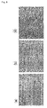
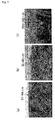
- Results of the evaluations are shown in Table 1, and SEM photographs (150 times magnification) of the surface of the SiC coat layer of each of the firing jigs manufactured in Examples 1 and 2, and Comparative Example 1 are shown in Figs. 6(a) to 6(c) . Also, SEM photographs (90 times magnification) of the cross section of the SiC coat layer of each of the firing jigs manufactured in Examples 1 and 2, and Comparative Example 1 are shown in Figs. 7(a) to 7(c) .
- the dense SiC coat layer having 4.5 ⁇ m of the surface roughness and 87 to 94 ⁇ m of the thickness of the SiC coat layer was formed. Also, peelings, cracks, and irregularities were not present on the SiC coat layer, and with respect to the stabilization of the average pore diameter of the honeycomb fired body, the stable value was obtained just after the manufacturing.
- the surface roughness of the SiC layer was 8.9 ⁇ m, and peelings and irregularities were not present on the SiC coat layer, so that it can be used without any problems; however, cracks were present in the SiC coat layer.
- Example 2 the surface roughness was 8.9 ⁇ m and the surface of the SiC coat layer was a little coarser in Example 2 than that in Example 1 in which the surface roughness was 4.5 ⁇ m and the SiC coat layer was dense, so that slight thermal stress was generated on the uppermost portion of the surface of the SiC coat layer and the thermal stress presumably caused the cracks.
- the cracks occurred in the SiC coat layer of the firing jig manufactured in Example 2, the cracks were not developed to cause peelings, and thus it is possible to use the firing jig without influencing on properties of the honeycomb fired body.
- the surface roughness of the SiC coat layer was 26.3 ⁇ m, cracks and peelings were present, and irregularities were also present on the SiC coat layer. Since the surface roughness was as large as 26.3 ⁇ m, it is presumed that slight thermal stress was generated on the surface of the SiC coat layer as in Example 2, and the thermal stress caused the cracks, and further the cracks developed due to heat to cause the peelings.
- Results of Examples 1 and 2, and Comparative Example 1 show that a surface roughness of a SiC coat layer is desirably 10 ⁇ m or less, and further desirably 5 ⁇ m or less in view of durability, exchange frequency, and the like. Also, with respect to the stabilization of the average pore diameter of the honeycomb fired body, the firing jig manufactured in Example 1 showed the stable value just after manufacturing, whereas the firing jig manufactured in Example 2 showed the stable value after two weeks. On the other hand, the firing jig manufactured in Comparative Example 1 took one month before the stabilization of the average pore diameter. The above-mentioned description shows that the firing jigs manufactured in Examples 1 and 2 are superior to that in Comparative Example 1 in view of the stabilization of the average pore diameter of the honeycomb fired body.
- a SiC coat layer is formed by using a forming material of the SiC coat layer, and then, a surface of the SiC coat layer is ground to obtain a SiC coat layer having a predetermined surface roughness.
- the embodiment of this kind is also included in the present invention.
- methods (A) to (D) for forming the SiC coat layer will be listed, and the following description will briefly discuss a method for grinding the formed SiC coat layer.
- a polymer mainly containing hydridopolycarbosilane and the like is applied to an area where a SiC coat layer is to be formed on the firing jig, and thereafter, a drying treatment and a firing treatment are carried out to form the SiC coat layer.
- a method for applying the polymer include spray coating, wash coating, brush application, instillation, printing, and the like.
- a mixture containing SiC particles and SiO 2 particles is applied to or placed on an area where a SiC coat layer is to be formed on the firing jig, and then a drying treatment and a firing treatment are carried out to form the SiC coat layer.
- the same application methods as those in the method (A) can be used for applying the mixture.
- organic solvents may be added to the mixture so as to easily apply or place the mixture.
- organic solvents include methyl cellulose, carboxymethyl cellulose, hydroxyethyl cellulose, polyethylene glycol, benzene, alcohols such as methanol, and the like.
- a firing treatment is carried out in a state that a material for recrystallization containing SiC particles and SiO 2 particles is placed on the firing jig, with inside of the firing furnace being under an atmosphere of SiO gas and CO gas, to form a coat layer comprising a recrystallized SiC on the surface of the firing jig.
- the coat layer comprising the recrystallized SiC it may be acceptable to form the coat layer comprising the recrystallized SiC on the surface of the firing jig by using the same method as the above-mentioned method, except that a material for recrystallization containing SiC particles with SiO 2 film formed on the surface of the particles is used in place of the material for recrystallization containing the SiC particles and the SiO 2 particles.
- the firing treatment may be carried out at a temperature of 1400 to 2300°C.
- a drying treatment and a degreasing treatment 200 to 500°C may be carried out on the material for recrystallization before the firing treatment.
- SiC derived from the material for recrystallization adheres to the surface of the firing jig as a recrystallized SiC in the firing treatment, so that the coat layer comprising the recrystallized SiC is formed.
- a mixture containing Si (silicon) and C (carbon) is applied to or placed on an area where a SiC coat layer is to be formed on the firing jig, and thereafter, for example, a firing treatment is carried out at a temperature of about 1800°C to form the coat layer comprising a reaction-sintered SiC.
- the SiC coat layer is formed on the surface of the firing jig by reaction sintering, so that the layer comprising the reaction-sintered SiC is formed.
- Examples of a method for grinding the SiC coat layer thus formed include a grinding with a buff or a grindstone, a grinding with a sheet, a scrub grinding, a blast grinding, a blast treatment, a polishing, and the like.
- Examples of the buff used in the grinding with a buff include: an abrasive grain-containing buff such as a disc buff, a flap buff, and a spiral buff; an abrasive grain-free buff such as a nonwoven polypropylene cloth; and the like.
- Examples of the abrasive grain used in the abrasive grain-containing buff include aluminum silicate, aluminum oxide, silicon carbide, and the like.
- the grindstone examples include a resinoid grindstone (resin type), magnesia grindstone (cement type), diamond grindstone, resin-bonded diamond grindstone, rubber control grindstone, epoxy control grindstone, and the like.
- a sheet containing an abrasive having a particle size of # A60 to A240 can be used as the sheet, and specific examples thereof include a urethane sponge, a nonwoven nylon cloth, a sheet formed by adhering abrasive grains such as aluminum silicate, aluminum oxide, and silicon carbide to acryl (sponge) and the like.
- Examples of the scrub grinding include a jet-scrub grinding, brush-scrub grinding, and the like. Also, examples of the blast grinding include micro-blast grinding, sand-blast grinding, and the like.
- a box-shaped housing body with its upper face open comprising carbon (DSG-332, manufactured by SEC Corp.), which comprises a bottom base and a frame base, was prepared, and a polymer for forming a SiC coat layer mainly containing allyl hydridopolycarbosilane (SP-MATRIX Polymer, manufactured by Starfire-Systems, Inc.) was applied to a placing face of the bottom base for a honeycomb molded body and a surface of the frame base.
- the housing body was dried at a temperature of 100°C for 12 hours, and then the housing body was repeatedly fired at a temperature of 2200°C for 2.5 hours seven times to form the SiC coat layer on the placing face of the housing body.
- the buff grinding with the disc buff was carried out on the placing face so as to adjust the surface roughness to 10 ⁇ m or less to form the SiC coat layer, so that a firing jig was manufactured.
- Fig. 8 is a SEM photograph showing a cross section of the firing jig before grinding.
- a firing jig was manufactured in the same manner as in the Example 3 except that the buff grinding was not carried out.
- Honeycomb fired bodies were manufactured by use of each of the firing jigs manufactured in Examples 3 and 4, and Comparative Example 2, in the same manner as in the method in which the honeycomb fired body was manufactured in the first embodiment.
- Example 3 the surface roughness of the SiC coat layer before the grinding was 27.5 ⁇ m and the surface roughness of the SiC coat layer after the grinding was 9.5 ⁇ m. Also, in Example 4, the surface roughness of the SiC coat layer before the grinding was 26.3 ⁇ m and the surface roughness of the SiC coat layer after the grinding was 6.6 ⁇ m. In both of Examples 3 and 4, peelings, cracks, and irregularities were not present on the coat layer, and the average pore diameter was stabilized in a month. On the other hand, in Comparative Example 2, the surface roughness of the SiC coat layer was as large as 28.1 ⁇ m. Also, cracks and peelings were present on the SiC coat layer.
- the average pore diameter was stabilized in a month as the same as in Example 3, but irregularities were present on the SiC coat layer. This is presumably because the unevenness of the coat layer was caused by that the polymer for forming a SiC coat layer was not uniformly applied to the surface of the housing body and that the application, drying, and firing of the polymer for forming a SiC coat layer were repeatedly carried out so as to form the SiC coat layer.
- the SiC coat layers before the grinding in Examples 3 and 4 were coarsely formed in the vicinity of the surface, and densely formed inside. Cracks tend to occur at a coarsely-formed surface portion of the SiC coat layer; however in Examples 3 and 4, since the coarsely-formed surface portion was ground so as to allow the dense portion formed at the inside to be exposed on the surface, it is possible to prevent peelings, cracks and the like from occurring after the grinding. Also, even in the case that irregularities are present on the surface of the SiC coat layer before the grinding, the irregularities are to be ground, so that it is possible to flatten the surface of the SiC coat layer.
- Examples of the method for forming a SiC coat layer include a chemical vapor-phase method such as a CVD (Chemical Vapor Deposition) method, a CVT (Chemical Vapor Transportation) method, and a CVI (Chemical Vapor Infiltration) method, a PVD (Physical Vapor Deposition) method, a liquid-phase method such as a liquid-phase epitaxy method, a sol-gel method, a DLC (Diamond Like Carbon) coating method, and a spraying method, a solid-phase method such as a solid-phase epitaxy method, and a recrystallization method, and the like.
- a chemical vapor-phase method such as a CVD (Chemical Vapor Deposition) method, a CVT (Chemical Vapor Transportation) method, and a CVI (Chemical Vapor Infiltration) method
- a PVD (Physical Vapor Deposition) method Physical Vapor Deposition) method
- the CVD method, the CVI method, the DLC coating method, the spraying method, and the recrystallization method are desirable, and particularly the CVD method and the CVI method are desirable. This is because the CVD method and the CVI method can make the surface roughness of the SiC coat layer small. Also, although the DLC coating method, the spraying method, and the recrystallization method tend to make the surface roughness of the SiC coat layer large, it is possible to make the surface roughness of the SiC coat layer small by forming the thick SiC coat layer and grinding the surface thereof.
- the SiC coat layer is formed by the vapor-phase method
- a method in which a heating treatment is carried out at a temperature of about 1000°C in the presence of CH 3 SiCl 3 and H 2 and a method in which a heating treatment is carried out at a temperature of 1500 to 1800°C in the presence of SiCl 4 and C 6 H 5 CH 3 can be used.
- a material of the spacer is not particularly limited as long as it can endure high temperatures upon firing, and silicon carbide, aluminum nitride, silicon nitride and the like can be used in addition to carbon.
- the shape of the spacer is not particularly limited, and a carbon felt having a cloth shape formed by combining carbon fibers, and a spacer having a shape formed by putting string-shaped carbon fibers together are desirable. This is because these shapes are not so hard that a honeycomb molded body tends not to be damaged.
- a honeycomb structured body manufactured in the present invention is not limited to a honeycomb structured body with a predetermined cell sealed.
- the honeycomb structured body with a predetermined cell sealed can be favorably used as a honeycomb filter, and the cell-unsealed honeycomb structured body can be favorably used as a catalyst supporting carrier. Therefore, the plug material paste is not necessarily filled into the cells and may be filled as needed in the method for manufacturing a honeycomb structured body of the present invention.
- the main component of the constituent material of the honeycomb structured body is not limited to silicon carbide, and examples of other ceramic materials include inorganic powders comprising the following materials: nitride ceramics such as aluminum nitride, silicon nitride, boron nitride, titanium nitride, and the like; carbide ceramics such as zirconium carbide, titanium carbide, tantalum carbide, tungsten carbide, and the like; oxide ceramics such as alumina, zirconia, cordierite, mullite, aluminum titanate, and the like.
- Non-oxide ceramics are desirable among these, and silicon carbide is particularly desirable due to its superior heat-resistance, mechanical strength, heat conductivity, and the like.
- examples of the constituent materials further include ceramic materials such as silicon-containing ceramics which are prepared by mixing the above-mentioned ceramics with metal silicon, and ceramics which are bonded by silicon or silicate composites, and the composite in which the metal silicon is mixed with silicon carbide (silicon-containing silicon carbide) is desirable among these.
- ceramic materials such as silicon-containing ceramics which are prepared by mixing the above-mentioned ceramics with metal silicon, and ceramics which are bonded by silicon or silicate composites, and the composite in which the metal silicon is mixed with silicon carbide (silicon-containing silicon carbide) is desirable among these.
- particle diameters of the silicon carbide powder is not particularly limited, and the silicon carbide powder that tends not to cause the case that the size of the honeycomb structured body manufactured by the following firing treatment becomes smaller than that of the honeycomb molded body after degreased is desirable.
- a powder containing 100 parts by weight of a powder having an average particle diameter of 1.0 to 50 ⁇ m and 5 to 65 parts by weight of a powder having an average particle diameter of 0.1 to 1.0 ⁇ m is desirable. It is required to adjust a firing temperature in order to adjust a pore diameter and the like of the honeycomb fired body; however, it is possible to adjust the pore diameter by adjusting the particle diameter of the inorganic powder.
- An organic binder in the wet mixture is not particularly limited, and examples thereof include methyl cellulose, carboxymethyl cellulose, hydroxyethyl cellulose, polyethylene glycol, and the like. Methyl cellulose is desirable among these. Generally, a blending amount of the organic binder is desirably 1 to 10 parts by weight to 100 parts by weight of the inorganic powder.
- the plasticizer in the wet mixture is not particularly limited, and examples thereof include glycerin and the like.
- the lubricant is not particularly limited, and examples thereof include polyoxy alkylene series composites such as polyoxyethylene alkyl ether, polyoxypropylene alkyl ether, and the like. Specific examples of the lubricant include polyoxyethylene monobutyl ether, polyoxypropylene monobutyl ether, and the like.
- the plasticizer and the lubricant may not be necessarily included in the mixed material powder.
- a dispersant solution may be used upon preparing the wet mixture, and examples thereof include water, organic solvents such as benzene, and alcohols such as methanol, and the like.
- a forming auxiliary may be added into the wet mixture.
- the forming auxiliary is not particularly limited, and examples thereof include ethylene glycol, dextrin, fatty acid, fatty acid soap, polyalcohol, and the like.
- balloons that are fine hollow spheres comprising oxide-based ceramics, spherical acrylic particles, graphite and the like may be added to the wet mixture as a pore-forming agent.
- the balloons are not particularly limited, and examples thereof include alumina balloons, glass micro balloons, shirasu balloons, fly ash balloons (FA balloons), mullite balloons, and the like. Alumina balloons are desirable among these.
- a temperature of the wet mixture containing a silicon carbide powder is desirably 28°C or less. In the case that the temperature is too high, the organic binder tends to be gelatinized. Also, the proportion of organic contents in the wet mixture is desirably 10% by weight or less, and the content of moisture is desirably 8 to 20% by weight.
- the plug material paste used for sealing the cells are not particularly limited, and those plug material pastes that allow the plugs manufactured through the following treatments to have a porosity of 30 to 75% are desirable, and for example, the same materials as those of the wet mixture can be used.
- the honeycomb fired bodies are preliminarily piled up one after another by interposing spacers, and then a sealing material paste is filled between the honeycomb fired bodies, so that an aggregated body of the honeycomb fired bodies may be manufactured.
- Examples of the inorganic binder used in the sealing material paste include silica sol, alumina sol, and the like. Each of these may be used alone or two or more kinds of these may be used in combination. Silica sol is desirable among the inorganic binders.
- Examples of the organic binder used in the sealing material paste include polyvinyl alcohol, methyl cellulose, ethyl cellulose, carboxymethyl cellulose, and the like. Each of these may be used alone or two or more kinds of these may be used in combination. Carboxymethyl cellulose is desirable among the organic binders.
- the examples of the inorganic fibers used in the sealing material paste include ceramic fibers such as silica-alumina fibers, mullite fibers, alumina fibers, and silica fibers. Each of these may be used alone or two or more kinds of these may be used in combination. Alumina fibers are desirable among the inorganic fibers.
- the examples of the inorganic particles used in the sealing material paste include carbides, nitrides, and the like. Specific examples include an inorganic powder comprising silicon carbide, silicon nitride and boron nitride, and the like. Each of these may be used alone, or two or more kinds of these may be used in combination. Silicon carbide is desirable among the inorganic particles due to its superior heat conductivity. Moreover, if necessary, the same pore-forming agent as that used in the wet mixture may be added into the sealing material paste.
- the drying treatment is not necessarily carried out, and may be carried out if necessary. Also, the drying treatment may be carried out after the plug material paste was charged into end portions of the cells. Also, upon drying the honeycomb molded body, a microwave drying apparatus, a hot-air drying apparatus, a reduced-pressure drying apparatus, a dielectric drying apparatus, a freeze drying apparatus, and the like may be used in addition to a drying apparatus in which microwave and hot air are used in combination.
- the degreasing treatment and the firing treatment are not necessarily carried out by using the same firing jig, and a degreasing jig which is not the same as the firing jig may be used upon degreasing.
- the degreased honeycomb molded body is taken from the degreasing jig and placed on the spacer which is placed in the firing jig, and then the firing treatment can be carried out.
- a catalyst may be supported on the honeycomb structured body manufactured in the present invention if necessary. Also, the catalyst may be supported on the honeycomb fired body before a honeycomb aggregated body is manufactured. In the case that the catalyst is supported, it is desirable that an alumina film having a large specific surface area is formed on the surface of the honeycomb structured body, and that a co-catalyst and the catalyst such as platinum are supported on a surface of the alumina film (layer).
Landscapes
- Chemical & Material Sciences (AREA)
- Engineering & Computer Science (AREA)
- Ceramic Engineering (AREA)
- Structural Engineering (AREA)
- Materials Engineering (AREA)
- Organic Chemistry (AREA)
- Inorganic Chemistry (AREA)
- Mechanical Engineering (AREA)
- General Engineering & Computer Science (AREA)
- Manufacturing & Machinery (AREA)
- Ceramic Products (AREA)
Applications Claiming Priority (1)
| Application Number | Priority Date | Filing Date | Title |
|---|---|---|---|
| PCT/JP2007/061480 WO2008149435A1 (fr) | 2007-06-06 | 2007-06-06 | Gabarit de cuisson et procédé de fabrication d'une structure en nid d'abeilles |
Publications (1)
| Publication Number | Publication Date |
|---|---|
| EP2014630A2 true EP2014630A2 (fr) | 2009-01-14 |
Family
ID=39248189
Family Applications (1)
| Application Number | Title | Priority Date | Filing Date |
|---|---|---|---|
| EP08000971A Withdrawn EP2014630A2 (fr) | 2007-06-06 | 2008-01-18 | Appareil de cuisson et procédé pour la fabrication d'un corps à structure en nid d'abeille |
Country Status (5)
| Country | Link |
|---|---|
| US (1) | US20080305259A1 (fr) |
| EP (1) | EP2014630A2 (fr) |
| KR (1) | KR20080107251A (fr) |
| CN (1) | CN101318826A (fr) |
| WO (1) | WO2008149435A1 (fr) |
Cited By (3)
| Publication number | Priority date | Publication date | Assignee | Title |
|---|---|---|---|---|
| CN102643095A (zh) * | 2012-04-16 | 2012-08-22 | 中国科学院金属研究所 | 一种SiC蜂窝陶瓷材料及其制备方法 |
| WO2019232153A1 (fr) * | 2018-05-31 | 2019-12-05 | Corning Incorporated | Procédé de fabrication de corps en nid d'abeilles |
| WO2019232152A1 (fr) * | 2018-05-31 | 2019-12-05 | Corning Incorporated | Procédé de fabrication de corps en nid d'abeilles |
Families Citing this family (74)
| Publication number | Priority date | Publication date | Assignee | Title |
|---|---|---|---|---|
| EP1719881B1 (fr) | 2002-02-05 | 2016-12-07 | Ibiden Co., Ltd. | Filtre a nid d'abeille pour la decontamination des gaz d'echappement, matiere adhesive et de revetement, et procede d'obtention dudit filtre |
| ATE374069T1 (de) * | 2002-03-15 | 2007-10-15 | Ibiden Co Ltd | Keramikfilter zur abgasreinigung |
| US20050169819A1 (en) | 2002-03-22 | 2005-08-04 | Ibiden Co., Ltd | Honeycomb filter for purifying exhaust gas |
| EP2020486A3 (fr) | 2002-04-10 | 2009-04-15 | Ibiden Co., Ltd. | Filtre à alvéoles servant à clarifier un gaz d'échappement |
| US20050153099A1 (en) * | 2002-04-11 | 2005-07-14 | Ibiden Co. Ltd. | Honeycomb filter for clarifying exhaust gases |
| US20060051556A1 (en) | 2003-09-12 | 2006-03-09 | Ibiden Co., Ltd. | Sintered ceramic compact and ceramic filter |
| JP4849891B2 (ja) | 2003-11-05 | 2012-01-11 | イビデン株式会社 | ハニカム構造体の製造方法 |
| JPWO2005108328A1 (ja) | 2004-05-06 | 2008-03-21 | イビデン株式会社 | ハニカム構造体及びその製造方法 |
| PL1647790T3 (pl) * | 2004-07-01 | 2009-01-30 | Ibiden Co Ltd | Sposób wytwarzania porowatego elementu ceramicznego |
| DE602005009635D1 (de) * | 2004-08-04 | 2008-10-23 | Ibiden Co Ltd | Brennofen und verfahren zur herstellung eines porösen keramikglieds damit |
| EP1666826A4 (fr) * | 2004-08-06 | 2008-04-09 | Ibiden Co Ltd | Four de frittage et procede de fabrication d'un corps fritte en ceramique poreuse a l'aide de ce four |
| EP1677063A4 (fr) * | 2004-08-25 | 2007-05-30 | Ibiden Co Ltd | KILN et méthode pour fabriquer un produit cuit céramique poreuse utilisant le KILN |
| EP1795262B1 (fr) * | 2004-09-30 | 2010-01-27 | Ibiden Co., Ltd. | Structure alvéolaire |
| WO2006082938A1 (fr) | 2005-02-04 | 2006-08-10 | Ibiden Co., Ltd. | Structure en nid d’abeille ceramique et procede de fabrication de celle-ci |
| JP2006223983A (ja) * | 2005-02-17 | 2006-08-31 | Ibiden Co Ltd | ハニカム構造体 |
| JP4812316B2 (ja) * | 2005-03-16 | 2011-11-09 | イビデン株式会社 | ハニカム構造体 |
| CN100453511C (zh) | 2005-03-28 | 2009-01-21 | 揖斐电株式会社 | 蜂窝结构体及密封材料 |
| WO2006103811A1 (fr) * | 2005-03-28 | 2006-10-05 | Ibiden Co., Ltd. | Structure en nid d’abeille |
| KR100822246B1 (ko) * | 2005-04-07 | 2008-04-16 | 이비덴 가부시키가이샤 | 허니컴 구조체 |
| WO2006117899A1 (fr) | 2005-04-28 | 2006-11-09 | Ibiden Co., Ltd. | Structure en nid d’abeille |
| ATE526252T1 (de) * | 2005-06-06 | 2011-10-15 | Ibiden Co Ltd | Verwendung eines verpackungsmaterials und verfahren für den transport eines wabenförmig strukturierten körpers |
| WO2007010643A1 (fr) * | 2005-07-21 | 2007-01-25 | Ibiden Co., Ltd. | Structure en nid d’abeille et appareil nettoyant un gaz d’échapement |
| WO2007023653A1 (fr) * | 2005-08-26 | 2007-03-01 | Ibiden Co., Ltd. | Structure en nid d’abeille et son procédé de production |
| CN101242937B (zh) * | 2005-10-05 | 2011-05-18 | 揖斐电株式会社 | 挤压成形用模具和多孔质陶瓷部件的制造方法 |
| CN100560180C (zh) * | 2005-11-18 | 2009-11-18 | 揖斐电株式会社 | 蜂窝结构体 |
| KR100855167B1 (ko) * | 2005-11-18 | 2008-08-29 | 이비덴 가부시키가이샤 | 벌집형 구조체 |
| CN101312809A (zh) * | 2005-12-26 | 2008-11-26 | 揖斐电株式会社 | 蜂窝结构体的制造方法 |
| WO2007074528A1 (fr) * | 2005-12-27 | 2007-07-05 | Ibiden Co., Ltd. | Gabarit de dégraissage, procédé de dégraissage de céramique moulée, et processus de fabrication de structure alvéolaire |
| WO2007086183A1 (fr) * | 2006-01-27 | 2007-08-02 | Ibiden Co., Ltd. | Structure en nid d'abeilles et processus pour sa production |
| WO2007086143A1 (fr) * | 2006-01-30 | 2007-08-02 | Ibiden Co., Ltd. | Procede d'inspection d'un corps de structure en nid d'abeilles et procede de production d'un corps de structure en nid d'abeilles |
| WO2007094075A1 (fr) | 2006-02-17 | 2007-08-23 | Ibiden Co., Ltd. | Unité d'assemblage et unité de desassemblage de dispositif de fixation pour le séchage, appareil de circulation dudit dispositif, procédé de séchage de moulage en céramique, et procédé de production de structure en nid d'abeille |
| JPWO2007097056A1 (ja) * | 2006-02-23 | 2009-07-09 | イビデン株式会社 | ハニカム構造体および排ガス浄化装置 |
| WO2007097000A1 (fr) * | 2006-02-24 | 2007-08-30 | Ibiden Co., Ltd. | Dispositif de scellage des extremites pour corps en nid d'abeille, procede d'application de materiau de scellement en pate et procede de production d'un corps a structure en nid d'abeille |
| WO2007096986A1 (fr) | 2006-02-24 | 2007-08-30 | Ibiden Co., Ltd. | Dispositif de chauffage de face d'extremite, procede de sechage de la face d'extremite d'un assemblage en nid d'abeille et procede de production de structures en nid d'abeille |
| DE602006002244D1 (de) | 2006-02-28 | 2008-09-25 | Ibiden Co Ltd | Trageelement für Trocknung, Trocknungsverfahren eines Presslings mit Wabenstruktur, und Verfahren zur Herstellung eines Wabenkörpers. |
| WO2007102216A1 (fr) | 2006-03-08 | 2007-09-13 | Ibiden Co., Ltd. | appareil pour introduction dans un four à dégraissage et processus de fabrication de structure alvéolaire |
| WO2007108076A1 (fr) * | 2006-03-17 | 2007-09-27 | Ibiden Co., Ltd. | Appareil de séchage, méthode de séchage d'une piece moulée céramique, et méthode de production d'une structure en nid d'abeille |
| JP4863904B2 (ja) * | 2006-03-31 | 2012-01-25 | イビデン株式会社 | ハニカム構造体およびその製造方法 |
| WO2007116529A1 (fr) * | 2006-04-11 | 2007-10-18 | Ibiden Co., Ltd. | appareil de découpe d'un article moulé, procédé de découpe d'un article moulé en céramique et processus pour produire une structure en nid d'abeille |
| WO2007122680A1 (fr) | 2006-04-13 | 2007-11-01 | Ibiden Co., Ltd. | Machine de moulage par extrusion, procédé de moulage par extrusion et procédé destiné à produire une structure en nid d'abeille |
| WO2007122707A1 (fr) * | 2006-04-19 | 2007-11-01 | Ibiden Co., Ltd. | Procédé permettant de produire une structure en nid d'abeille |
| WO2007122716A1 (fr) * | 2006-04-20 | 2007-11-01 | Ibiden Co., Ltd. | Dispositif de transport et procédé de fabrication d'une structure en nid d'abeilles |
| WO2007122715A1 (fr) * | 2006-04-20 | 2007-11-01 | Ibiden Co., Ltd. | Méthode d'inspection d'un corps cuit en nid d'abeilles et procédé de fabrication d'une structure en nid d'abeilles |
| WO2007129391A1 (fr) | 2006-05-01 | 2007-11-15 | Ibiden Co., Ltd. | Unité de montage de gabarit de cuisson, unité de démontage de gabarit de cuisson, appareil de circulation, procédé de moulage de céramique de cuisson, et processus de production de structure de nid d'abeille |
| WO2007129399A1 (fr) * | 2006-05-08 | 2007-11-15 | Ibiden Co., Ltd. | PROCÉDÉ DE FABRICATION D'UNE STRUCTURE EN NID D'ABEILLES, MACHINE DE RÉCePTION DE MOULAGES EN NID D'ABEILLES ET MACHINE DE DÉMONTAGE DE MOULAGES EN NID D'ABEILLES |
| WO2007132530A1 (fr) * | 2006-05-17 | 2007-11-22 | Ibiden Co., Ltd. | Appareil de finition de face d'extrémité pour moulage alvéolaire, procédé d'obturation de moulage alvéolaire et processus de fabrication de structure alvéolaire |
| WO2007138701A1 (fr) | 2006-05-31 | 2007-12-06 | Ibiden Co., Ltd. | Dispositif de maintien et procédé de production de structure alvéolaire |
| ATE425852T1 (de) * | 2006-07-07 | 2009-04-15 | Ibiden Co Ltd | Apparat und verfahren zur bearbeitung der endflache eines wabenkírpers und verfahren zur herstellung eines wabenkírpers |
| WO2008032391A1 (fr) * | 2006-09-14 | 2008-03-20 | Ibiden Co., Ltd. | Procédé de production d'une structure en nid d'abeille et composition de matière première pour nid d'abeille calciné |
| DE602006014830D1 (de) | 2006-09-14 | 2010-07-22 | Ibiden Co Ltd | Verfahren zur Herstellung eines Wabenkörpers und Zusammensetzung für Sinterwabenkörper |
| WO2008032390A1 (fr) * | 2006-09-14 | 2008-03-20 | Ibiden Co., Ltd. | Procédé de production d'une structure en nid d'abeille |
| BRPI0715565A2 (pt) | 2006-10-19 | 2013-07-02 | Univ Arkansas Board Of Regents | mÉtodos e aparelho para fazer revestimentos usando pulverizaÇço eletrostÁtica |
| MX349614B (es) | 2006-10-19 | 2017-07-26 | Nanomech Inc | Metodos y aparatos para elaborar recubrimientos utilizando deposicion de rocio ultrasonico. |
| WO2008090625A1 (fr) * | 2007-01-26 | 2008-07-31 | Ibiden Co., Ltd. | Appareil pour former une couche périphérique externe et procédé de fabrication d'une structure en nid d'abeilles |
| WO2008099454A1 (fr) * | 2007-02-09 | 2008-08-21 | Ibiden Co., Ltd. | Structure en nid d'abeilles et appareil de traitement de gaz d'échappement |
| WO2008099450A1 (fr) * | 2007-02-09 | 2008-08-21 | Ibiden Co., Ltd. | Structure en nid d'abeilles et appareil de traitement de gaz d'échappement |
| EP1982966B1 (fr) * | 2007-03-29 | 2011-11-09 | Ibiden Co., Ltd. | Structure en nid d'abeille et son procédé de production |
| WO2008120385A1 (fr) * | 2007-03-29 | 2008-10-09 | Ibiden Co., Ltd. | Structure de nid d'abeilles, son procédé de fabrication, appareil de purification de gaz d'échappement et procédé de fabrication de l'appareil |
| WO2008126320A1 (fr) * | 2007-03-30 | 2008-10-23 | Ibiden Co., Ltd. | Procédé de fabrication d'une structure en nid d'abeilles |
| WO2008155856A1 (fr) | 2007-06-21 | 2008-12-24 | Ibiden Co., Ltd. | Structure en nid d'abeille et son procédé de production |
| WO2009066388A1 (fr) | 2007-11-21 | 2009-05-28 | Ibiden Co., Ltd. | Structure en nid-d'abeilles et son procédé de production |
| WO2009101683A1 (fr) * | 2008-02-13 | 2009-08-20 | Ibiden Co., Ltd. | Processus de production d'une structure en nid d'abeilles |
| WO2009101682A1 (fr) | 2008-02-13 | 2009-08-20 | Ibiden Co., Ltd. | Structure en nid d'abeilles, appareil de purification de gaz d'échappement et processus de production d'une structure en nid d'abeilles |
| JPWO2009107230A1 (ja) | 2008-02-29 | 2011-06-30 | イビデン株式会社 | ハニカム構造体用シール材、ハニカム構造体、及び、ハニカム構造体の製造方法 |
| WO2009118814A1 (fr) | 2008-03-24 | 2009-10-01 | イビデン株式会社 | Filtre en nid d'abeilles |
| WO2009118813A1 (fr) | 2008-03-24 | 2009-10-01 | イビデン株式会社 | Structure en nid d'abeille et son procédé de production |
| TWI371376B (en) * | 2011-05-20 | 2012-09-01 | Carbotec Ind Co Ltd | Method of making a bicycle rim |
| JP6476047B2 (ja) * | 2015-04-22 | 2019-02-27 | イビデン株式会社 | 焼成冶具の製造方法 |
| CN105666678A (zh) * | 2016-01-08 | 2016-06-15 | 宜兴中村窑业有限公司 | 一种碳化硅板的成型机 |
| JP6953348B2 (ja) * | 2018-03-30 | 2021-10-27 | 日本碍子株式会社 | コーティング材、外周コート炭化珪素系ハニカム構造体、及び炭化珪素系ハニカム構造体の外周をコーティングする方法 |
| CN110923664A (zh) * | 2019-11-28 | 2020-03-27 | 宜兴王子制陶有限公司 | 一种二维增强的蜂窝结构体成形模具涂层的制备方法 |
| JP2023096455A (ja) * | 2021-12-27 | 2023-07-07 | 株式会社エフ・シー・シー | セラミック焼成用セッター及びその製造方法 |
| JPWO2024195173A1 (fr) * | 2023-03-17 | 2024-09-26 | ||
| CN118405927B (zh) * | 2024-04-28 | 2026-03-03 | 江苏赛威德电子材料有限公司 | 一种改性RB-SiC陶瓷及其制备方法 |
Citations (1)
| Publication number | Priority date | Publication date | Assignee | Title |
|---|---|---|---|---|
| WO2007015550A1 (fr) | 2005-08-03 | 2007-02-08 | Ibiden Co., Ltd. | Gabarit pour la cuisson de carbure de silicium et procédé de production d’un corps poreux de carbure de silicium |
Family Cites Families (97)
| Publication number | Priority date | Publication date | Assignee | Title |
|---|---|---|---|---|
| JPH0681713B2 (ja) * | 1990-04-05 | 1994-10-19 | 三井造船株式会社 | 断熱材 |
| JPH06305862A (ja) * | 1993-04-19 | 1994-11-01 | Toyo Tanso Kk | 炭化ケイ素被覆黒鉛部材 |
| JPH0727487A (ja) * | 1993-07-13 | 1995-01-27 | Mitsubishi Materials Corp | 焼成用治具 |
| EP1382443B1 (fr) * | 1996-01-12 | 2013-04-24 | Ibiden Co., Ltd. | Filtre pour purifier de gaz d'échappement |
| JPH1135391A (ja) * | 1997-05-20 | 1999-02-09 | Topy Ind Ltd | 炭化ケイ素被覆サセプタ− |
| ES2341274T3 (es) * | 1999-09-29 | 2010-06-17 | Ibiden Co., Ltd. | Filtro de panal y conjunto de filtro ceramico. |
| EP1403231B1 (fr) * | 2001-05-31 | 2012-11-21 | Ibiden Co., Ltd. | Procede de production d'un corps ceramique fritté poreux |
| EP1719881B1 (fr) * | 2002-02-05 | 2016-12-07 | Ibiden Co., Ltd. | Filtre a nid d'abeille pour la decontamination des gaz d'echappement, matiere adhesive et de revetement, et procede d'obtention dudit filtre |
| DE60318937T3 (de) * | 2002-03-04 | 2013-10-10 | Ibiden Co., Ltd. | Verwendung eines wabenfilters zur abgasreinigung |
| ATE374069T1 (de) * | 2002-03-15 | 2007-10-15 | Ibiden Co Ltd | Keramikfilter zur abgasreinigung |
| US20050169819A1 (en) * | 2002-03-22 | 2005-08-04 | Ibiden Co., Ltd | Honeycomb filter for purifying exhaust gas |
| JPWO2003084640A1 (ja) * | 2002-04-09 | 2005-08-11 | イビデン株式会社 | 排気ガス浄化用ハニカムフィルタ |
| EP2020486A3 (fr) * | 2002-04-10 | 2009-04-15 | Ibiden Co., Ltd. | Filtre à alvéoles servant à clarifier un gaz d'échappement |
| US20050153099A1 (en) * | 2002-04-11 | 2005-07-14 | Ibiden Co. Ltd. | Honeycomb filter for clarifying exhaust gases |
| JP2003306392A (ja) * | 2002-04-12 | 2003-10-28 | Toshiba Ceramics Co Ltd | 電子部品用セラミックスの熱処理用治具およびその製造方法 |
| WO2004076027A1 (fr) * | 2003-02-28 | 2004-09-10 | Ibiden Co., Ltd. | Structure ceramique en nids d'abeilles |
| CN100386505C (zh) * | 2003-05-06 | 2008-05-07 | 揖斐电株式会社 | 蜂巢式结构体 |
| JP3683572B2 (ja) * | 2003-05-07 | 2005-08-17 | 株式会社コーテック | Cvd用反応容器 |
| US20060051556A1 (en) * | 2003-09-12 | 2006-03-09 | Ibiden Co., Ltd. | Sintered ceramic compact and ceramic filter |
| JP4849891B2 (ja) * | 2003-11-05 | 2012-01-11 | イビデン株式会社 | ハニカム構造体の製造方法 |
| EP1698604B1 (fr) * | 2003-11-12 | 2009-05-27 | Ibiden Co., Ltd. | Corps a structure en ceramique |
| US7387829B2 (en) * | 2004-01-13 | 2008-06-17 | Ibiden Co., Ltd. | Honeycomb structure, porous body, pore forming material for the porous body, and methods for manufacturing the pore forming material, the porous body and the honeycomb structure |
| WO2005099865A1 (fr) * | 2004-04-05 | 2005-10-27 | Ibiden Co., Ltd. | Structure alvéolaire, procédé de fabrication de structure alvéolaire, et dispositif de contrôle d’émission d’échappement |
| JPWO2005108328A1 (ja) * | 2004-05-06 | 2008-03-21 | イビデン株式会社 | ハニカム構造体及びその製造方法 |
| CN101249350B (zh) * | 2004-05-18 | 2012-02-22 | 揖斐电株式会社 | 蜂窝结构体及废气净化装置 |
| PL1647790T3 (pl) * | 2004-07-01 | 2009-01-30 | Ibiden Co Ltd | Sposób wytwarzania porowatego elementu ceramicznego |
| DE602005009635D1 (de) * | 2004-08-04 | 2008-10-23 | Ibiden Co Ltd | Brennofen und verfahren zur herstellung eines porösen keramikglieds damit |
| JPWO2006013931A1 (ja) * | 2004-08-04 | 2008-05-01 | イビデン株式会社 | 焼成炉及びその焼成炉を用いた多孔質セラミック焼成体の製造方法 |
| WO2006013652A1 (fr) * | 2004-08-04 | 2006-02-09 | Ibiden Co., Ltd. | Four de cuisson continue et procédé de fabrication d’élément de céramique poreuse à l’aide de celui-ci |
| EP1666826A4 (fr) * | 2004-08-06 | 2008-04-09 | Ibiden Co Ltd | Four de frittage et procede de fabrication d'un corps fritte en ceramique poreuse a l'aide de ce four |
| CN1973171B (zh) * | 2004-08-10 | 2010-05-05 | 揖斐电株式会社 | 烧制炉及利用该烧制炉制造陶瓷部件的方法 |
| EP1677063A4 (fr) * | 2004-08-25 | 2007-05-30 | Ibiden Co Ltd | KILN et méthode pour fabriquer un produit cuit céramique poreuse utilisant le KILN |
| JPWO2006035823A1 (ja) * | 2004-09-30 | 2008-05-15 | イビデン株式会社 | ハニカム構造体 |
| EP1795262B1 (fr) * | 2004-09-30 | 2010-01-27 | Ibiden Co., Ltd. | Structure alvéolaire |
| EP1808217B1 (fr) * | 2004-10-12 | 2009-07-22 | Ibiden Co., Ltd. | Structure alveolaire ceramique |
| JP5142532B2 (ja) * | 2004-11-26 | 2013-02-13 | イビデン株式会社 | ハニカム構造体 |
| KR100820619B1 (ko) * | 2004-12-28 | 2008-04-08 | 이비덴 가부시키가이샤 | 필터 및 필터 집합체 |
| WO2006082938A1 (fr) * | 2005-02-04 | 2006-08-10 | Ibiden Co., Ltd. | Structure en nid d’abeille ceramique et procede de fabrication de celle-ci |
| DE602006012406D1 (de) * | 2005-02-04 | 2010-04-08 | Ibiden Co Ltd | Keramikwabenstruktur |
| JP2006223983A (ja) * | 2005-02-17 | 2006-08-31 | Ibiden Co Ltd | ハニカム構造体 |
| JP4812316B2 (ja) * | 2005-03-16 | 2011-11-09 | イビデン株式会社 | ハニカム構造体 |
| CN100453511C (zh) * | 2005-03-28 | 2009-01-21 | 揖斐电株式会社 | 蜂窝结构体及密封材料 |
| WO2006103811A1 (fr) * | 2005-03-28 | 2006-10-05 | Ibiden Co., Ltd. | Structure en nid d’abeille |
| CN101146742B (zh) * | 2005-03-30 | 2013-05-01 | 揖斐电株式会社 | 含碳化硅颗粒、制造碳化硅质烧结体的方法、碳化硅质烧结体以及过滤器 |
| KR100822246B1 (ko) * | 2005-04-07 | 2008-04-16 | 이비덴 가부시키가이샤 | 허니컴 구조체 |
| JP2006289237A (ja) * | 2005-04-08 | 2006-10-26 | Ibiden Co Ltd | ハニカム構造体 |
| WO2006117899A1 (fr) * | 2005-04-28 | 2006-11-09 | Ibiden Co., Ltd. | Structure en nid d’abeille |
| JPWO2006126278A1 (ja) * | 2005-05-27 | 2008-12-25 | イビデン株式会社 | ハニカム構造体 |
| ATE526252T1 (de) * | 2005-06-06 | 2011-10-15 | Ibiden Co Ltd | Verwendung eines verpackungsmaterials und verfahren für den transport eines wabenförmig strukturierten körpers |
| WO2007010643A1 (fr) * | 2005-07-21 | 2007-01-25 | Ibiden Co., Ltd. | Structure en nid d’abeille et appareil nettoyant un gaz d’échapement |
| WO2007023653A1 (fr) * | 2005-08-26 | 2007-03-01 | Ibiden Co., Ltd. | Structure en nid d’abeille et son procédé de production |
| CN101146589B (zh) * | 2005-09-28 | 2010-11-24 | 揖斐电株式会社 | 蜂窝式过滤器 |
| CN101242937B (zh) * | 2005-10-05 | 2011-05-18 | 揖斐电株式会社 | 挤压成形用模具和多孔质陶瓷部件的制造方法 |
| CN100560180C (zh) * | 2005-11-18 | 2009-11-18 | 揖斐电株式会社 | 蜂窝结构体 |
| KR100855167B1 (ko) * | 2005-11-18 | 2008-08-29 | 이비덴 가부시키가이샤 | 벌집형 구조체 |
| US20070187651A1 (en) * | 2005-12-26 | 2007-08-16 | Kazuya Naruse | Method for mixing powder, agitation apparatus, and method for manufacturing honeycomb structured body |
| CN101312809A (zh) * | 2005-12-26 | 2008-11-26 | 揖斐电株式会社 | 蜂窝结构体的制造方法 |
| WO2007074528A1 (fr) * | 2005-12-27 | 2007-07-05 | Ibiden Co., Ltd. | Gabarit de dégraissage, procédé de dégraissage de céramique moulée, et processus de fabrication de structure alvéolaire |
| CN101312895A (zh) * | 2005-12-27 | 2008-11-26 | 揖斐电株式会社 | 搬运装置和蜂窝结构体的制造方法 |
| WO2007086183A1 (fr) * | 2006-01-27 | 2007-08-02 | Ibiden Co., Ltd. | Structure en nid d'abeilles et processus pour sa production |
| WO2007086143A1 (fr) * | 2006-01-30 | 2007-08-02 | Ibiden Co., Ltd. | Procede d'inspection d'un corps de structure en nid d'abeilles et procede de production d'un corps de structure en nid d'abeilles |
| WO2007094075A1 (fr) * | 2006-02-17 | 2007-08-23 | Ibiden Co., Ltd. | Unité d'assemblage et unité de desassemblage de dispositif de fixation pour le séchage, appareil de circulation dudit dispositif, procédé de séchage de moulage en céramique, et procédé de production de structure en nid d'abeille |
| JPWO2007097056A1 (ja) * | 2006-02-23 | 2009-07-09 | イビデン株式会社 | ハニカム構造体および排ガス浄化装置 |
| WO2007097000A1 (fr) * | 2006-02-24 | 2007-08-30 | Ibiden Co., Ltd. | Dispositif de scellage des extremites pour corps en nid d'abeille, procede d'application de materiau de scellement en pate et procede de production d'un corps a structure en nid d'abeille |
| WO2007097004A1 (fr) * | 2006-02-24 | 2007-08-30 | Ibiden Co., Ltd. | Appareil et procede de melangeage a l'etat humide et procede de production de structures en nid d'abeille |
| WO2007096986A1 (fr) * | 2006-02-24 | 2007-08-30 | Ibiden Co., Ltd. | Dispositif de chauffage de face d'extremite, procede de sechage de la face d'extremite d'un assemblage en nid d'abeille et procede de production de structures en nid d'abeille |
| ATE551167T1 (de) * | 2006-02-28 | 2012-04-15 | Ibiden Co Ltd | Verfahren zur herstellung von einem wabenstrukturkörper |
| WO2007102216A1 (fr) * | 2006-03-08 | 2007-09-13 | Ibiden Co., Ltd. | appareil pour introduction dans un four à dégraissage et processus de fabrication de structure alvéolaire |
| WO2007102217A1 (fr) * | 2006-03-08 | 2007-09-13 | Ibiden Co., Ltd. | refroidisseur de corps cuit, four de cuisson, procédé de refroidissement de corps cuit céramique, et processus de fabrication de structure alvéolaire |
| WO2007108076A1 (fr) * | 2006-03-17 | 2007-09-27 | Ibiden Co., Ltd. | Appareil de séchage, méthode de séchage d'une piece moulée céramique, et méthode de production d'une structure en nid d'abeille |
| WO2007116529A1 (fr) * | 2006-04-11 | 2007-10-18 | Ibiden Co., Ltd. | appareil de découpe d'un article moulé, procédé de découpe d'un article moulé en céramique et processus pour produire une structure en nid d'abeille |
| WO2007122680A1 (fr) * | 2006-04-13 | 2007-11-01 | Ibiden Co., Ltd. | Machine de moulage par extrusion, procédé de moulage par extrusion et procédé destiné à produire une structure en nid d'abeille |
| WO2007122707A1 (fr) * | 2006-04-19 | 2007-11-01 | Ibiden Co., Ltd. | Procédé permettant de produire une structure en nid d'abeille |
| WO2007122715A1 (fr) * | 2006-04-20 | 2007-11-01 | Ibiden Co., Ltd. | Méthode d'inspection d'un corps cuit en nid d'abeilles et procédé de fabrication d'une structure en nid d'abeilles |
| WO2007129390A1 (fr) * | 2006-05-01 | 2007-11-15 | Ibiden Co., Ltd. | Unité de montage de gabarit de dégraissage, unité de démontage de gabarit de dégraissage, appareil de sirculation de gabarit de dégraissage. procédé de dégraissage de soudage en céramique, et processus de production de structure en nid d'abeilles |
| WO2007129391A1 (fr) * | 2006-05-01 | 2007-11-15 | Ibiden Co., Ltd. | Unité de montage de gabarit de cuisson, unité de démontage de gabarit de cuisson, appareil de circulation, procédé de moulage de céramique de cuisson, et processus de production de structure de nid d'abeille |
| WO2007129399A1 (fr) * | 2006-05-08 | 2007-11-15 | Ibiden Co., Ltd. | PROCÉDÉ DE FABRICATION D'UNE STRUCTURE EN NID D'ABEILLES, MACHINE DE RÉCePTION DE MOULAGES EN NID D'ABEILLES ET MACHINE DE DÉMONTAGE DE MOULAGES EN NID D'ABEILLES |
| WO2007132530A1 (fr) * | 2006-05-17 | 2007-11-22 | Ibiden Co., Ltd. | Appareil de finition de face d'extrémité pour moulage alvéolaire, procédé d'obturation de moulage alvéolaire et processus de fabrication de structure alvéolaire |
| WO2007138701A1 (fr) * | 2006-05-31 | 2007-12-06 | Ibiden Co., Ltd. | Dispositif de maintien et procédé de production de structure alvéolaire |
| ATE425852T1 (de) * | 2006-07-07 | 2009-04-15 | Ibiden Co Ltd | Apparat und verfahren zur bearbeitung der endflache eines wabenkírpers und verfahren zur herstellung eines wabenkírpers |
| WO2008032391A1 (fr) * | 2006-09-14 | 2008-03-20 | Ibiden Co., Ltd. | Procédé de production d'une structure en nid d'abeille et composition de matière première pour nid d'abeille calciné |
| WO2008032390A1 (fr) * | 2006-09-14 | 2008-03-20 | Ibiden Co., Ltd. | Procédé de production d'une structure en nid d'abeille |
| DE602006014830D1 (de) * | 2006-09-14 | 2010-07-22 | Ibiden Co Ltd | Verfahren zur Herstellung eines Wabenkörpers und Zusammensetzung für Sinterwabenkörper |
| WO2008047404A1 (fr) * | 2006-10-16 | 2008-04-24 | Ibiden Co., Ltd. | Support de montage pour structure alvéolaire et dispositif d'inspection pour structure alvéolaire |
| WO2008090625A1 (fr) * | 2007-01-26 | 2008-07-31 | Ibiden Co., Ltd. | Appareil pour former une couche périphérique externe et procédé de fabrication d'une structure en nid d'abeilles |
| WO2008099454A1 (fr) * | 2007-02-09 | 2008-08-21 | Ibiden Co., Ltd. | Structure en nid d'abeilles et appareil de traitement de gaz d'échappement |
| WO2008099450A1 (fr) * | 2007-02-09 | 2008-08-21 | Ibiden Co., Ltd. | Structure en nid d'abeilles et appareil de traitement de gaz d'échappement |
| WO2008114335A1 (fr) * | 2007-02-21 | 2008-09-25 | Ibiden Co., Ltd. | Four de chauffage et procédé de fabrication de structure en nid d'abeille |
| WO2008120385A1 (fr) * | 2007-03-29 | 2008-10-09 | Ibiden Co., Ltd. | Structure de nid d'abeilles, son procédé de fabrication, appareil de purification de gaz d'échappement et procédé de fabrication de l'appareil |
| WO2008120386A1 (fr) * | 2007-03-29 | 2008-10-09 | Ibiden Co., Ltd. | Structure de nid d'abeilles |
| EP1982966B1 (fr) * | 2007-03-29 | 2011-11-09 | Ibiden Co., Ltd. | Structure en nid d'abeille et son procédé de production |
| WO2008126319A1 (fr) * | 2007-03-30 | 2008-10-23 | Ibiden Co., Ltd. | Procédé de fabrication de comprimés frittés de carbure de silicium poreux |
| WO2008126320A1 (fr) * | 2007-03-30 | 2008-10-23 | Ibiden Co., Ltd. | Procédé de fabrication d'une structure en nid d'abeilles |
| WO2008129691A1 (fr) * | 2007-03-30 | 2008-10-30 | Ibiden Co., Ltd. | Filtre en nid d'abeilles |
| WO2008139581A1 (fr) * | 2007-05-09 | 2008-11-20 | Ibiden Co., Ltd. | Procédé de production d'une matière première pour la cuisson de carbure de silicium et procédé de production d'une structure en nid d'abeille |
| JP5180835B2 (ja) * | 2007-10-31 | 2013-04-10 | イビデン株式会社 | ハニカム構造体用梱包体、及び、ハニカム構造体の輸送方法 |
| WO2009066388A1 (fr) * | 2007-11-21 | 2009-05-28 | Ibiden Co., Ltd. | Structure en nid-d'abeilles et son procédé de production |
-
2007
- 2007-06-06 WO PCT/JP2007/061480 patent/WO2008149435A1/fr not_active Ceased
-
2008
- 2008-01-18 EP EP08000971A patent/EP2014630A2/fr not_active Withdrawn
- 2008-04-07 KR KR1020080032313A patent/KR20080107251A/ko not_active Ceased
- 2008-04-11 CN CN200810092443.2A patent/CN101318826A/zh active Pending
- 2008-04-18 US US12/106,168 patent/US20080305259A1/en not_active Abandoned
Patent Citations (1)
| Publication number | Priority date | Publication date | Assignee | Title |
|---|---|---|---|---|
| WO2007015550A1 (fr) | 2005-08-03 | 2007-02-08 | Ibiden Co., Ltd. | Gabarit pour la cuisson de carbure de silicium et procédé de production d’un corps poreux de carbure de silicium |
Cited By (6)
| Publication number | Priority date | Publication date | Assignee | Title |
|---|---|---|---|---|
| CN102643095A (zh) * | 2012-04-16 | 2012-08-22 | 中国科学院金属研究所 | 一种SiC蜂窝陶瓷材料及其制备方法 |
| CN102643095B (zh) * | 2012-04-16 | 2013-10-09 | 中国科学院金属研究所 | 一种SiC蜂窝陶瓷材料及其制备方法 |
| WO2019232153A1 (fr) * | 2018-05-31 | 2019-12-05 | Corning Incorporated | Procédé de fabrication de corps en nid d'abeilles |
| WO2019232152A1 (fr) * | 2018-05-31 | 2019-12-05 | Corning Incorporated | Procédé de fabrication de corps en nid d'abeilles |
| US11866375B2 (en) | 2018-05-31 | 2024-01-09 | Corning Incorporated | Honeycomb body manufacturing methods |
| US11919822B2 (en) | 2018-05-31 | 2024-03-05 | Corning Incorporated | Honeycomb body manufacturing methods |
Also Published As
| Publication number | Publication date |
|---|---|
| US20080305259A1 (en) | 2008-12-11 |
| KR20080107251A (ko) | 2008-12-10 |
| WO2008149435A1 (fr) | 2008-12-11 |
| CN101318826A (zh) | 2008-12-10 |
Similar Documents
| Publication | Publication Date | Title |
|---|---|---|
| US20080305259A1 (en) | Firing jig and method for manufacturing honeycomb structure | |
| US7951324B2 (en) | Method for manufacturing honeycomb structure | |
| EP1902766B1 (fr) | Procédé de construction d'un corps en forme de nid d' abeilles. | |
| EP1832565A1 (fr) | Gabarit pour la cuisson de carbure de silicium et procédé de production d un corps poreux de carbure de silicium | |
| EP1974884B1 (fr) | Procédé de fabrication d'un élément structuré en nid d'abeille | |
| JP2007230859A (ja) | ハニカム構造体の製造方法 | |
| US20080237942A1 (en) | Method for manufacturing porous silicon carbide sintered body | |
| EP1847366B1 (fr) | Procédé pour la fabrication d'une structure en nid d'abeilles | |
| US8124002B2 (en) | Extrusion-molding machine, extrusion-molding method, and method for manufacturing honeycomb structured body | |
| US9506391B2 (en) | Honeycomb structure | |
| CN101069859B (zh) | 蜂窝状结构及其制造方法 | |
| US20080067725A1 (en) | Method for manufacturing honeycomb structure and material composition for honeycomb fired body | |
| EP2792396B1 (fr) | Structure en nid d'abeille | |
| EP1647790A1 (fr) | Dispositif de serrage pour céramique de cuisson et méthode de fabrication de corps en céramique poreuse | |
| US20080111274A1 (en) | Degreasing jig assembling apparatus, degreasing jig disassembling apparatus, degreasing jig circulating apparatus, method for degreasing ceramic molded body, and method for manufacturing honeycomb structured body | |
| US20080136053A1 (en) | Cooling apparatus for fired body, firing furnace, cooling method of ceramic fired body, and method for manufacturing honeycomb structure | |
| EP1772242A1 (fr) | Filière pour l'extrusion et procédé de fabrication de corps poreux en céramique | |
| US20080284067A1 (en) | Method for manufacturing material for silicon carbide fired body and method for manufacturing honeycomb structure | |
| US20090252919A1 (en) | Honeycomb structure and method for manufacturing the same | |
| US8349432B2 (en) | Honeycomb structure and method for manufacturing honeycomb structure | |
| WO2007132530A1 (fr) | Appareil de finition de face d'extrémité pour moulage alvéolaire, procédé d'obturation de moulage alvéolaire et processus de fabrication de structure alvéolaire | |
| JP5057815B2 (ja) | ハニカム成形体用端面処理装置、ハニカム成形体の封止方法、及び、ハニカム構造体の製造方法 | |
| US20090242100A1 (en) | Method for manufacturing honeycomb structure | |
| EP2481542A1 (fr) | Structure de nid d'abeilles et son procédé de fabrication | |
| JP5171308B2 (ja) | 焼成用治具及びハニカム構造体の製造方法 |
Legal Events
| Date | Code | Title | Description |
|---|---|---|---|
| PUAI | Public reference made under article 153(3) epc to a published international application that has entered the european phase |
Free format text: ORIGINAL CODE: 0009012 |
|
| PUAI | Public reference made under article 153(3) epc to a published international application that has entered the european phase |
Free format text: ORIGINAL CODE: 0009012 |
|
| 17P | Request for examination filed |
Effective date: 20080118 |
|
| AK | Designated contracting states |
Kind code of ref document: A2 Designated state(s): AT BE BG CH CY CZ DE DK EE ES FI FR GB GR HR HU IE IS IT LI LT LU LV MC MT NL NO PL PT RO SE SI SK TR |
|
| AX | Request for extension of the european patent |
Extension state: AL BA MK RS |
|
| STAA | Information on the status of an ep patent application or granted ep patent |
Free format text: STATUS: THE APPLICATION HAS BEEN WITHDRAWN |
|
| 18W | Application withdrawn |
Effective date: 20100604 |