EP2014811A1 - Procédé de fonctionnement d'un métier à tricoter à mailles jettées et métier à tricoter chaîne - Google Patents
Procédé de fonctionnement d'un métier à tricoter à mailles jettées et métier à tricoter chaîne Download PDFInfo
- Publication number
- EP2014811A1 EP2014811A1 EP07013353A EP07013353A EP2014811A1 EP 2014811 A1 EP2014811 A1 EP 2014811A1 EP 07013353 A EP07013353 A EP 07013353A EP 07013353 A EP07013353 A EP 07013353A EP 2014811 A1 EP2014811 A1 EP 2014811A1
- Authority
- EP
- European Patent Office
- Prior art keywords
- main shaft
- axis
- knitting machine
- virtual
- warp knitting
- Prior art date
- Legal status (The legal status is an assumption and is not a legal conclusion. Google has not performed a legal analysis and makes no representation as to the accuracy of the status listed.)
- Granted
Links
Images
Classifications
-
- D—TEXTILES; PAPER
- D04—BRAIDING; LACE-MAKING; KNITTING; TRIMMINGS; NON-WOVEN FABRICS
- D04B—KNITTING
- D04B27/00—Details of, or auxiliary devices incorporated in, warp knitting machines, restricted to machines of this kind
- D04B27/06—Needle bars; Sinker bars
- D04B27/08—Driving devices therefor
-
- D—TEXTILES; PAPER
- D04—BRAIDING; LACE-MAKING; KNITTING; TRIMMINGS; NON-WOVEN FABRICS
- D04B—KNITTING
- D04B27/00—Details of, or auxiliary devices incorporated in, warp knitting machines, restricted to machines of this kind
-
- D—TEXTILES; PAPER
- D04—BRAIDING; LACE-MAKING; KNITTING; TRIMMINGS; NON-WOVEN FABRICS
- D04B—KNITTING
- D04B27/00—Details of, or auxiliary devices incorporated in, warp knitting machines, restricted to machines of this kind
- D04B27/10—Devices for supplying, feeding, or guiding threads to needles
- D04B27/24—Thread guide bar assemblies
- D04B27/26—Shogging devices therefor
Definitions
- the invention relates to a method for operating a warp knitting machine with a main shaft driven by a main shaft drive, in which one controls at least one follower drive in response to a master axis.
- the invention relates to a warp knitting machine with a main shaft driven by a main shaft drive, at least one follower drive and a control device for controlling the follower drive in response to a master axis.
- a method and a warp knitting machine of this kind are out DE 42 15 798 C2 known.
- the main shaft is driven by a main shaft drive.
- By the main shaft of a warp knitting machine usually different elements of the knitting machine are driven, for example, a knitting needle or pivot lever for guide bars.
- Other elements of the knitting machine are driven by follower drives.
- warp beams of the knitting machine are driven by follower drives to provide the required amount of thread for the knitting process available.
- the follower drive or the following drives must be operated synchronously with the main shaft.
- the movements of the patterning needles must be matched to the movements of the knitting needles in order to produce the desired patterns in the knitted fabric and to avoid collisions between the knitting needles and the guide needles.
- the invention has for its object to provide a warp knitting machine with high productivity. This object is achieved in a method of the type mentioned above in that one generates a virtual master axis and controls the slave drive in dependence on the virtual master axis.
- the main shaft rotates in continuous operation, although at a constant speed. Accordingly, the or the following drives would have to be able to work equally well.
- the speed or the rotational speed of the main shaft is constant but only on average.
- the main shaft is subject to certain speed changes during one revolution. This may be due to the fact that the load of the main shaft changes in one revolution. For example, if the main shaft or associated parts in a portion of the revolution must lift the knitting needle bar, then the main shaft will momentarily rotate slower than average in that portion of the revolution. If, however, in another section of the revolution, the knitting needle bar is lowered again, then there will be a short-term increase in the speed of the main shaft.
- a virtual master axis can be generated relatively easily, for example by a master axis generator or by appropriate hardware and software components.
- the virtual master axis then forms, as it were, the basis for the motion control of the driven parts of the warp knitting machine.
- the main shaft drive is controlled as a function of the virtual master axis.
- the main shaft drive is controlled as a function of the virtual master axis.
- a real master axis is generated by means of the main shaft. So you still uses an encoder arrangement on the main shaft, which provides continuous information about the current angular position of the main shaft. This is a security feature. In addition, you can integrate this real master axis in a position control for the main shaft.
- the real master axis and the virtual master axis are continuously compared with each other. It is thus easy to monitor the synchronization between the virtual master and the real master. For example, it is possible to determine by simple experiments which velocity profile the main shaft has in one revolution. Accordingly, permissible deviations between the virtual master axis and the real master axis can basically be defined for each rotational angle position of the main shaft. This makes it possible to monitor whether the virtual master axis and the real master axis coincide with one another so far that trouble-free operation of the warp knitting machine is made possible.
- the control of the slave drive is controlled from the virtual master axis to the real master axis.
- This is for example a simple way to bring the warp knitting machine from a standstill to the desired rated speed or to change the speed of the warp knitting machine.
- the virtual Leading axis is particularly advantageous in situations in which it is important to produce in a continuous operation as uniform as possible, that is free of harmonics signal that generates the angular position of the main shaft. In other situations, this "smooth" signal may be dispensable.
- an error is used as a criterion for switching.
- An error would be, for example, excessive divergence of virtual master axis and real master axis, ie a "following error" that exceeds a predetermined limit.
- the limit value of the following error can also be parameterized, ie change with operating conditions of the warp knitting machine. Another mistake would be a power failure. In this case, the follower drives must follow the main shaft drive until the machine stops. Switching to the real master axis simplifies this operating state. The same applies to the operating mode "emergency stop".
- the virtual master axis is formed by signals that correspond to transmitter signals. In this case you can take over the follower or the drives practically unchanged. These then react just as well to the output signals of encoders.
- variable speed speed profile is used to generate the virtual master.
- Predetermined pattern sections may be, for example, those pattern sections in which the pattern-laying needles have a large offset path. Lowering the speed of the main shaft in this range will leave more time for the pattern pegs to travel the appropriate offset path. Once the predetermined pattern section has passed, the speed can be increased again and an overload of the following drives involved in critical pattern transitions is avoided.
- switching points are generated at points of the virtual leading axis which correspond to predetermined rotational angle positions of the main shaft.
- the virtual master axis it is possible to generate so-called “trigger points” as software switching marks at specific angular positions of the main shaft rotation and to derive corresponding control commands for the machine control.
- the advantage of this procedure is that a so-called “angle-synchronous cam controller” can be realized in a simple manner.
- control device has a leading axis generator for generating a virtual leading axis.
- the main shaft drive is operable as a follower drive in dependence on the virtual master axis.
- the virtual leading axis is therefore no longer used merely as the basis for the movement of the following axes, i. the following drives, but also for the drive of the main shaft. This makes it possible in a simple manner to synchronize the main shaft and driven by the following drives or other parts of the knitting machine.
- the main shaft has an encoder arrangement with which the rotational angle positions of the main shaft are detected. So you will continue to gain information about the rotation angle of the main shaft. This information can be used to control the angular position of the main shaft through a position control loop. However, one can also use this information of the encoder arrangement to generate a real master axis.
- control device has a monitoring device which determines a deviation between the real master axis and the virtual master axis.
- the real master axis will deviate from the virtual master axis, thus forming a following error. This is also permitted within certain limits. It is now possible, on the basis of the comparison between the real and the virtual master axis, to monitor whether the warp knitting machine is still working within a permissible range or whether an error is to be feared.
- control device is switchable between the real and the virtual master axis. This not only relies on the virtual master axis but can also use the real master axis if required.
- the control device preferably has an error detection device, depending on the output signal of which it can be switched between the real and the virtual master axis.
- An error detection device can detect, for example, a power failure or an emergency stop. It is also possible for the error detection device to output an error signal if the deviation between the real master axis and the virtual master axis becomes too large. In this case, you will lean on the real leading axis, which then have to follow the follower drives.
- the master axis generator generates encoder signals.
- Encoder signals for example, signals of incremental, absolute, SinCos - encoder signals or the like have generally defined shapes, to which the following drives are adapted. Now you can configure the master axis generator so that it generates similar signals, so that you can continue to use the follower drives without major changes.
- a speed profile generator is assigned to the leading axis generator.
- the speed profiler controls the speed, which is determined by the virtual master axis, depending on a particular program that is specified for a knitted fabric. For example, you can make specific speed changes here. For example, if the knitted fabric has a pattern portion in which complicated patterning becomes necessary or patterning with large offsets due to the knitting needles, then in such a pattern portion, the number of revolutions of the main shaft can be reduced to allow enough time for the pattern pegs to move ,
- the speed profiler can also control certain ramps and transitions, so that even with a speed change of the main shaft, the follower drives are not overly burdened.
- the master axis generator Preferably, the master axis generator generates trigger signals at predetermined angular positions of the main shaft. This gives a simple way the above-mentioned "angle synchronous cam switch". The trigger signals can then be used as control commands for the machine control or one can derive the control commands thereof.
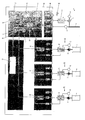
- a warp knitting machine 1 shown only very schematically has a main shaft 2, which is driven by a main shaft drive 3.
- the main shaft drive 3 is controlled by a drive amplifier 4.
- the drive amplifier 4 in turn is connected to an angle encoder 5, which continuously determines the rotational angle position of the main shaft drive 3.
- the main shaft 2 is also connected to an angle encoder 6, which continuously determines the angular position of the main shaft.
- the warp knitting machine 1 also has a plurality of follower drives 19 - 21, for example for the controlled movement of a pattern guide bar or a warp beam.
- follower drives 19-21 are shown here, wherein the respective driven element is simply referred to as "following axis" 7-9.
- Each following axis 7-9 is driven by a motor 10-12.
- Each motor 10 - 12 is connected to an angle encoder 13 - 15, which further reports the current rotational position of the motor 10 - 12 to a drive amplifier 16 - 18.
- the drive amplifier 16 - 18 controls the motor 10 - 12, which then causes the corresponding following axis 7 - 9 in accordance with the movement of the main shaft 2.
- the main shaft 2 drives in a manner not shown further elements of the warp knitting machine 1, for example, a knitting needle or pivot lever for guide bars.
- the main shaft 2 is to be operated in steady-state operation at a constant speed.
- rotational speed changes i. E. for example, the main shaft 2 turns a little slower when it needs to lift the needle bar. It turns faster when it lowers the needle bar.
- the follower drives 19-21 Even if these speed changes are only small during one revolution, they can, without additional measures, nevertheless lead to the follower drives 19-21 also receiving these speed fluctuations and the following axes 7 - 9 having to drive accordingly. This leads to unnecessary current peaks in the follower drives 19 - 21.
- control device 22 also referred to as "machine control".
- the control device 22 has a leading axis generator 23 which generates a virtual leading axis.
- the virtual master axis is a signal that maps the rotational movement of the main shaft 2, wherein one This signal can be designed so that it reflects the theoretically ideal rotational movement of the main shaft 2.
- the follower drives 19 - 21 can be controlled.
- the virtual master axis 24 can be kept free of rotational speed changes. It therefore transmits an harmonic-free or harmonic-poor signal to the follower drives 19-21.
- the control device 22 has an adjusting device 25, here in the form of a potentiometer, in order to set the rotational speed of the main shaft 2.
- the conversion of the signal from the setting device 25 into a signal which is understandable for the control device 22 takes place via an interface device 26.
- the signal from the setting device 25 is fed via a normalization device 27 to a speed profiler 28, which can perform a sequential setpoint change for the leading axis generator 23.
- a speed curve for the main shaft 2 can be set for a specific pattern.
- the main shaft 2 may be rotated more slowly during certain patterning operations to provide more time for these patterning operations in the knitwear. Then, when the corresponding patterning operation is completed, the rotational speed of the main shaft 2 can be increased again, so that overall high productivity can be achieved.
- the drive amplifier 4 of the main shaft drive 3 is supplied by a position controller 29 with control signals.
- the position controller 29 gets as a target value the virtual Leading axis 24.
- the current angular position of the main shaft 2 is supplied, which is determined by the angle encoder 6.
- the position controller thus ensures that the main shaft 2 follows as a "real master axis" of the virtual master axis 24.
- the virtual master axis 24 is also supplied to position controllers 30-32 of the follower drives 19-21.
- the position controllers 30 - 32 receive information corresponding to the actual values from the drive amplifiers 16 - 18 which they in turn derive from the angle encoders 13 - 15.
- the position controllers 30-32 must drive much less unnecessary acceleration and braking operations.
- the real master axis 33 not only serves as the actual value for the position controller 29, but is also supplied to a comparator 34.
- the comparison device 34 continuously compares the virtual master axis 24 with the real master axis 33. These two master axes 24, 33 will not coincide congruently. Due to the above-described load changes in one revolution, deviations may result. As long as these deviations, the so-called "following error", remain within a certain range, they are permissible. However, if the following error exceeds a limit value, the operation of the warp knitting machine 1 is switched over by a switch 35 so that it is no longer the virtual leading axis 24 but the real leading axis 33 that is used as default for the follower drives 19-21. A switch 36 takes over in this case, the speed signal from the Adjustment device 25, so that the main shaft 2 can continue to operate at the predetermined speed. Incidentally, the warp knitting machine 1 can then optionally be moved down.
- the limit value for the following error can be parameterizable, i. You can adapt it to different operating conditions, such as speeds.
- Another error monitor 37 is provided. This monitors, for example, whether an operating voltage is present. In the event of failure of the operating voltage or upon actuation of an "emergency stop", the warp knitting machine 1 is also switched over from operation with the virtual master shaft 24 to the operation with the real master shaft 33.
- the real master 33 is still forwarded to an operating data and machine data acquisition 38, so that the operation of the warp knitting machine 1 can be logged on the basis of the behavior of the main shaft 2.
- the virtual master axis 24 is also reported back to the speed profiler 28, so that the speed profile generator 28, for example, depending on the performed revolutions of the main shaft 2 can set the speed.
- each revolution of the main shaft 2 stands for one course in the knitwear. Since one knows in certain knitting patterns in the knitted fabric on which course a more complicated sampling takes place, it is possible to reduce the speed of the main shaft 2 precisely at this course or at the corresponding courses.
- leading-axis generator 23 it generates trigger signals at predetermined "rotational angle positions" of the lead axle 24, corresponding to the corresponding rotational angle positions of the main shaft 2, which trigger signals can then be used for the generation of main-shaft-position-dependent control commands. This simulates an "angle-synchronous cam controller".
- the switches 35, 36 can also be realized by software switches, which are switched depending on the operating conditions and service settings.
- the position controllers 29 - 32 and optionally also other elements can be realized by program-controlled microprocessors.
Landscapes
- Engineering & Computer Science (AREA)
- Textile Engineering (AREA)
- Knitting Machines (AREA)
Priority Applications (3)
| Application Number | Priority Date | Filing Date | Title |
|---|---|---|---|
| EP07013353.3A EP2014811B1 (fr) | 2007-07-07 | 2007-07-07 | Procédé de fonctionnement d'un métier à tricoter à mailles jettées et métier à tricoter chaîne |
| CN2007103062870A CN101339425B (zh) | 2007-07-07 | 2007-11-05 | 经编机的运行方法和经编机 |
| KR1020070112132A KR20090004336A (ko) | 2007-07-07 | 2007-11-05 | 체인 편직장치의 작동 방법 및 체인 편직장치 |
Applications Claiming Priority (1)
| Application Number | Priority Date | Filing Date | Title |
|---|---|---|---|
| EP07013353.3A EP2014811B1 (fr) | 2007-07-07 | 2007-07-07 | Procédé de fonctionnement d'un métier à tricoter à mailles jettées et métier à tricoter chaîne |
Publications (2)
| Publication Number | Publication Date |
|---|---|
| EP2014811A1 true EP2014811A1 (fr) | 2009-01-14 |
| EP2014811B1 EP2014811B1 (fr) | 2013-09-11 |
Family
ID=39581816
Family Applications (1)
| Application Number | Title | Priority Date | Filing Date |
|---|---|---|---|
| EP07013353.3A Not-in-force EP2014811B1 (fr) | 2007-07-07 | 2007-07-07 | Procédé de fonctionnement d'un métier à tricoter à mailles jettées et métier à tricoter chaîne |
Country Status (3)
| Country | Link |
|---|---|
| EP (1) | EP2014811B1 (fr) |
| KR (1) | KR20090004336A (fr) |
| CN (1) | CN101339425B (fr) |
Cited By (3)
| Publication number | Priority date | Publication date | Assignee | Title |
|---|---|---|---|---|
| EP2826902A1 (fr) * | 2013-07-19 | 2015-01-21 | Kufner Textil GmbH | Procédé de fabrication d'un élément de chauffage de surface textile |
| CN106054793A (zh) * | 2016-06-17 | 2016-10-26 | 江南大学 | 一种经编机花型进度跟踪和控制装置及控制方法 |
| EP3205761B1 (fr) * | 2016-02-10 | 2021-12-15 | KARL MAYER STOLL R&D GmbH | Métier à tricoter à chaîne |
Families Citing this family (1)
| Publication number | Priority date | Publication date | Assignee | Title |
|---|---|---|---|---|
| CN101858014B (zh) * | 2010-05-20 | 2011-08-17 | 常州市第八纺织机械有限公司 | 双轴向经编机十轴同步控制方法 |
Citations (3)
| Publication number | Priority date | Publication date | Assignee | Title |
|---|---|---|---|---|
| DE2349931A1 (de) * | 1973-02-26 | 1974-09-05 | Sigma Instruments Inc | Verfahren zur mustersteuerung der maschenbildungswerkzeuge von wirk- und strickmaschinen und einrichtung zur durchfuehrung des verfahrens |
| DE4215798C2 (de) | 1992-05-13 | 1994-03-24 | Mayer Textilmaschf | Kettenwirkmaschine |
| DE19963990A1 (de) | 1999-12-31 | 2001-07-19 | Mayer Textilmaschf | Kettenwirkmaschine mit Mustereinrichtung |
Family Cites Families (3)
| Publication number | Priority date | Publication date | Assignee | Title |
|---|---|---|---|---|
| DE4238600C2 (de) * | 1992-11-16 | 1996-09-26 | Kaendler Maschinenbau Gmbh | Elektronische Steuereinheit für Textilmaschinen, insbesondere für Wirkmaschinen |
| DE20000582U1 (de) * | 2000-01-14 | 2000-03-30 | Karl Mayer Textilmaschinenfabrik Gmbh, 63179 Obertshausen | Kettenwirkmaschine |
| DE10224429B4 (de) * | 2002-06-01 | 2007-11-29 | Karl Mayer Textilmaschinenfabrik Gmbh | Wirkmaschine, insbesondere Kettenwirkmaschine |
-
2007
- 2007-07-07 EP EP07013353.3A patent/EP2014811B1/fr not_active Not-in-force
- 2007-11-05 KR KR1020070112132A patent/KR20090004336A/ko not_active Abandoned
- 2007-11-05 CN CN2007103062870A patent/CN101339425B/zh not_active Expired - Fee Related
Patent Citations (3)
| Publication number | Priority date | Publication date | Assignee | Title |
|---|---|---|---|---|
| DE2349931A1 (de) * | 1973-02-26 | 1974-09-05 | Sigma Instruments Inc | Verfahren zur mustersteuerung der maschenbildungswerkzeuge von wirk- und strickmaschinen und einrichtung zur durchfuehrung des verfahrens |
| DE4215798C2 (de) | 1992-05-13 | 1994-03-24 | Mayer Textilmaschf | Kettenwirkmaschine |
| DE19963990A1 (de) | 1999-12-31 | 2001-07-19 | Mayer Textilmaschf | Kettenwirkmaschine mit Mustereinrichtung |
Cited By (7)
| Publication number | Priority date | Publication date | Assignee | Title |
|---|---|---|---|---|
| EP2826902A1 (fr) * | 2013-07-19 | 2015-01-21 | Kufner Textil GmbH | Procédé de fabrication d'un élément de chauffage de surface textile |
| WO2015007533A1 (fr) * | 2013-07-19 | 2015-01-22 | Kufner Textil Gmbh | Procédé de fabrication d'un élément chauffant plat textile |
| TWI570290B (zh) * | 2013-07-19 | 2017-02-11 | 庫佛奈爾控股有限公司 | 產生纖維表面加熱元件的方法及複式襯緯系統 |
| EA031560B1 (ru) * | 2013-07-19 | 2019-01-31 | Куфнер Холдинг Гмбх | Способ изготовления тканевого нагревательного элемента поверхностного типа |
| US10349468B2 (en) | 2013-07-19 | 2019-07-09 | Kufner Holding Gmbh | Method for producing a textile sheet heating element |
| EP3205761B1 (fr) * | 2016-02-10 | 2021-12-15 | KARL MAYER STOLL R&D GmbH | Métier à tricoter à chaîne |
| CN106054793A (zh) * | 2016-06-17 | 2016-10-26 | 江南大学 | 一种经编机花型进度跟踪和控制装置及控制方法 |
Also Published As
| Publication number | Publication date |
|---|---|
| EP2014811B1 (fr) | 2013-09-11 |
| KR20090004336A (ko) | 2009-01-12 |
| CN101339425A (zh) | 2009-01-07 |
| CN101339425B (zh) | 2010-12-29 |
Similar Documents
| Publication | Publication Date | Title |
|---|---|---|
| EP0742503B1 (fr) | Dispositif pour la commande numérique d'une machine-outil ou d'un robot | |
| DE4215798C2 (de) | Kettenwirkmaschine | |
| EP0527192B1 (fr) | Procede de commande des mouvements de la molette d'une machine de fluotournage et machine de fluotournage pour mettre en oeuvre ce procede | |
| EP1917564B1 (fr) | Procede et dispositif pour commander et reguler le mouvement du poussoir sur des presses servo-electriques | |
| DE10131806A1 (de) | Verfahren und Vorrichtung zum Betreiben eines dezentralen Steuersystems | |
| DE2704375C2 (de) | System zur Erzeugung von Folgen von digitalen Sollwerten | |
| EP2014811B1 (fr) | Procédé de fonctionnement d'un métier à tricoter à mailles jettées et métier à tricoter chaîne | |
| WO2002018264A1 (fr) | Systeme de securite redondant d'un vehicule | |
| DE102008047684B4 (de) | Wirkmaschine, insbesondere Kettenwirkmaschine | |
| DE4215691C2 (de) | Kettenwirkmaschine | |
| DE69413007T2 (de) | Verfahren zum Steuern vom horizontalen Versatz der Hülsentragbarren in Beziehung mit vorher bestimmten Distanzen zwischen den Nadelmitten an Strickmaschinen | |
| EP1055755A2 (fr) | Dispositif de réglage pour les cames de métiers à tricoter rectilignes | |
| DE102019112717A1 (de) | Antriebssystem für einen Schalter und ein Verfahren zum Antreiben eines Schalters | |
| EP1372965B1 (fr) | Procede de reglage de registre | |
| EP0139926B1 (fr) | Métier à tricoter rectiligne à cueillage (système Cotton) | |
| DE69100887T2 (de) | Verfahren und Gerät zum Steuern einer oder mehrerer Achsen einer Werkzeugmaschine. | |
| DE2125093A1 (fr) | ||
| EP2302118A1 (fr) | Procédé et machine à tricoter destinés à la fabrication de marchandises tricotées selon le motif rayure | |
| DE10333010B4 (de) | Verfahren zum Betreiben einer schnell laufenden Wirkmaschine | |
| DE10224429B4 (de) | Wirkmaschine, insbesondere Kettenwirkmaschine | |
| EP1592829B1 (fr) | Metiers a tricoter | |
| DE3824547C2 (de) | Verfahren zur Steuerung eines auf Handbetrieb umschaltbaren motorischen Antriebs, Motorsteuerung mit Umschaltung auf Handbetrieb und deren Verwendung | |
| DE19962143B4 (de) | Wirkmaschine, insbesondere Kettenwirkmaschine | |
| DE1930522C3 (de) | Rundstrickmaschine | |
| DE102007031093B4 (de) | Verfahren zum Betreiben einer Kettenwirkmaschine und Kettenwirkmaschine |
Legal Events
| Date | Code | Title | Description |
|---|---|---|---|
| PUAI | Public reference made under article 153(3) epc to a published international application that has entered the european phase |
Free format text: ORIGINAL CODE: 0009012 |
|
| 17P | Request for examination filed |
Effective date: 20081011 |
|
| AK | Designated contracting states |
Kind code of ref document: A1 Designated state(s): AT BE BG CH CY CZ DE DK EE ES FI FR GB GR HU IE IS IT LI LT LU LV MC MT NL PL PT RO SE SI SK TR |
|
| AX | Request for extension of the european patent |
Extension state: AL BA HR MK RS |
|
| AKX | Designation fees paid |
Designated state(s): CH DE ES IT LI |
|
| GRAP | Despatch of communication of intention to grant a patent |
Free format text: ORIGINAL CODE: EPIDOSNIGR1 |
|
| INTG | Intention to grant announced |
Effective date: 20130607 |
|
| GRAS | Grant fee paid |
Free format text: ORIGINAL CODE: EPIDOSNIGR3 |
|
| GRAA | (expected) grant |
Free format text: ORIGINAL CODE: 0009210 |
|
| AK | Designated contracting states |
Kind code of ref document: B1 Designated state(s): CH DE ES IT LI |
|
| REG | Reference to a national code |
Ref country code: CH Ref legal event code: EP |
|
| REG | Reference to a national code |
Ref country code: DE Ref legal event code: R096 Ref document number: 502007012255 Country of ref document: DE Effective date: 20131107 |
|
| PG25 | Lapsed in a contracting state [announced via postgrant information from national office to epo] |
Ref country code: ES Free format text: LAPSE BECAUSE OF FAILURE TO SUBMIT A TRANSLATION OF THE DESCRIPTION OR TO PAY THE FEE WITHIN THE PRESCRIBED TIME-LIMIT Effective date: 20130911 |
|
| REG | Reference to a national code |
Ref country code: DE Ref legal event code: R097 Ref document number: 502007012255 Country of ref document: DE |
|
| PLBE | No opposition filed within time limit |
Free format text: ORIGINAL CODE: 0009261 |
|
| STAA | Information on the status of an ep patent application or granted ep patent |
Free format text: STATUS: NO OPPOSITION FILED WITHIN TIME LIMIT |
|
| 26N | No opposition filed |
Effective date: 20140612 |
|
| REG | Reference to a national code |
Ref country code: DE Ref legal event code: R097 Ref document number: 502007012255 Country of ref document: DE Effective date: 20140612 |
|
| PGFP | Annual fee paid to national office [announced via postgrant information from national office to epo] |
Ref country code: CH Payment date: 20140722 Year of fee payment: 8 Ref country code: DE Payment date: 20140717 Year of fee payment: 8 |
|
| PGFP | Annual fee paid to national office [announced via postgrant information from national office to epo] |
Ref country code: IT Payment date: 20140729 Year of fee payment: 8 |
|
| REG | Reference to a national code |
Ref country code: DE Ref legal event code: R119 Ref document number: 502007012255 Country of ref document: DE |
|
| REG | Reference to a national code |
Ref country code: CH Ref legal event code: PL |
|
| PG25 | Lapsed in a contracting state [announced via postgrant information from national office to epo] |
Ref country code: DE Free format text: LAPSE BECAUSE OF NON-PAYMENT OF DUE FEES Effective date: 20160202 Ref country code: IT Free format text: LAPSE BECAUSE OF NON-PAYMENT OF DUE FEES Effective date: 20150707 Ref country code: LI Free format text: LAPSE BECAUSE OF NON-PAYMENT OF DUE FEES Effective date: 20150731 Ref country code: CH Free format text: LAPSE BECAUSE OF NON-PAYMENT OF DUE FEES Effective date: 20150731 |