EP2014844A1 - Sichtschutzeinrichtung - Google Patents
Sichtschutzeinrichtung Download PDFInfo
- Publication number
- EP2014844A1 EP2014844A1 EP08018439A EP08018439A EP2014844A1 EP 2014844 A1 EP2014844 A1 EP 2014844A1 EP 08018439 A EP08018439 A EP 08018439A EP 08018439 A EP08018439 A EP 08018439A EP 2014844 A1 EP2014844 A1 EP 2014844A1
- Authority
- EP
- European Patent Office
- Prior art keywords
- frame
- brackets
- frame legs
- snap
- wing
- Prior art date
- Legal status (The legal status is an assumption and is not a legal conclusion. Google has not performed a legal analysis and makes no representation as to the accuracy of the status listed.)
- Granted
Links
- 238000012216 screening Methods 0.000 claims description 10
- 230000000007 visual effect Effects 0.000 claims description 10
- 239000004033 plastic Substances 0.000 claims description 4
- 230000001681 protective effect Effects 0.000 claims 1
- 230000037431 insertion Effects 0.000 abstract 1
- 238000003780 insertion Methods 0.000 abstract 1
- 238000009434 installation Methods 0.000 description 5
- 238000010276 construction Methods 0.000 description 3
- 230000015572 biosynthetic process Effects 0.000 description 2
- 239000004744 fabric Substances 0.000 description 2
- 238000006243 chemical reaction Methods 0.000 description 1
- 238000002347 injection Methods 0.000 description 1
- 239000007924 injection Substances 0.000 description 1
- 230000003993 interaction Effects 0.000 description 1
- 230000013011 mating Effects 0.000 description 1
- 238000000034 method Methods 0.000 description 1
- 239000002991 molded plastic Substances 0.000 description 1
- 230000035515 penetration Effects 0.000 description 1
- 239000012815 thermoplastic material Substances 0.000 description 1
Images




Classifications
-
- A—HUMAN NECESSITIES
- A47—FURNITURE; DOMESTIC ARTICLES OR APPLIANCES; COFFEE MILLS; SPICE MILLS; SUCTION CLEANERS IN GENERAL
- A47G—HOUSEHOLD OR TABLE EQUIPMENT
- A47G5/00—Screens; Draught-deflectors
-
- E—FIXED CONSTRUCTIONS
- E04—BUILDING
- E04B—GENERAL BUILDING CONSTRUCTIONS; WALLS, e.g. PARTITIONS; ROOFS; FLOORS; CEILINGS; INSULATION OR OTHER PROTECTION OF BUILDINGS
- E04B2/00—Walls, e.g. partitions, for buildings; Wall construction with regard to insulation; Connections specially adapted to walls
- E04B2/74—Removable non-load-bearing partitions; Partitions with a free upper edge
- E04B2/7407—Removable non-load-bearing partitions; Partitions with a free upper edge assembled using frames with infill panels or coverings only; made-up of panels and a support structure incorporating posts
- E04B2/7416—Removable non-load-bearing partitions; Partitions with a free upper edge assembled using frames with infill panels or coverings only; made-up of panels and a support structure incorporating posts with free upper edge, e.g. for use as office space dividers
- E04B2/7422—Removable non-load-bearing partitions; Partitions with a free upper edge assembled using frames with infill panels or coverings only; made-up of panels and a support structure incorporating posts with free upper edge, e.g. for use as office space dividers with separate framed panels without intermediary support posts
- E04B2/7427—Removable non-load-bearing partitions; Partitions with a free upper edge assembled using frames with infill panels or coverings only; made-up of panels and a support structure incorporating posts with free upper edge, e.g. for use as office space dividers with separate framed panels without intermediary support posts with adjustable angular connection of panels
- E04B2/7431—Removable non-load-bearing partitions; Partitions with a free upper edge assembled using frames with infill panels or coverings only; made-up of panels and a support structure incorporating posts with free upper edge, e.g. for use as office space dividers with separate framed panels without intermediary support posts with adjustable angular connection of panels using hinges having two parallel rotation axes
-
- E—FIXED CONSTRUCTIONS
- E04—BUILDING
- E04B—GENERAL BUILDING CONSTRUCTIONS; WALLS, e.g. PARTITIONS; ROOFS; FLOORS; CEILINGS; INSULATION OR OTHER PROTECTION OF BUILDINGS
- E04B2/00—Walls, e.g. partitions, for buildings; Wall construction with regard to insulation; Connections specially adapted to walls
- E04B2/74—Removable non-load-bearing partitions; Partitions with a free upper edge
- E04B2002/7479—Details of connection of flexible sheets to frame or posts
-
- F—MECHANICAL ENGINEERING; LIGHTING; HEATING; WEAPONS; BLASTING
- F16—ENGINEERING ELEMENTS AND UNITS; GENERAL MEASURES FOR PRODUCING AND MAINTAINING EFFECTIVE FUNCTIONING OF MACHINES OR INSTALLATIONS; THERMAL INSULATION IN GENERAL
- F16B—DEVICES FOR FASTENING OR SECURING CONSTRUCTIONAL ELEMENTS OR MACHINE PARTS TOGETHER, e.g. NAILS, BOLTS, CIRCLIPS, CLAMPS, CLIPS OR WEDGES; JOINTS OR JOINTING
- F16B7/00—Connections of rods or tubes, e.g. of non-circular section, mutually, including resilient connections
- F16B7/04—Clamping or clipping connections
- F16B7/0433—Clamping or clipping connections for rods or tubes being in parallel relationship
Definitions
- the invention relates to a screening device.
- Screening devices are known as fixed shelves in the form of so-called screens or Spanish walls for the division of interiors. Mainly these screens are used to subdivide open-plan offices and are known as heavy, even sound-absorbing constructions. For outdoor use visual or windbreaker elements are known as lightweight cloth constructions, wherein the cloth is stretched between tentered by strings and ground anchors tent poles. Such lightweight screens are intended for temporary use only. These are not suitable for installation on terraces and balconies.
- the invention is therefore an object of the invention to provide a visual protection device that is relatively easy and simple design, but is suitable for permanent installation on terraces and balconies.
- a visual protection device comprising at least two pivotally interconnected wings as each provided with privacy shield frame, of which two approximately mutually parallel frame legs adjacent wings are connected to each other with the respective frame leg a hinge forming brackets, the brackets each form with at least one frame leg in at least one angular position a positive locking.
- Such a device according to the invention may be provided for wall mounting or for floor installation.
- the respectively forming a hinge with the frame legs of the wings brackets allow easy mating of different frame wings.
- the fact that the brackets interact at least partially positively with the frame legs of the wings a simple alignment of the wings of a visual protection device can achieve each other.
- the brackets each form two approximately C-shaped receptacles for the frame legs, which embrace this in the mounted position.
- the receptacles are each formed by resiliently formed retaining arms, can be clipped together in a simple manner, several wings of the screening device according to the invention.
- brackets are integrally formed of plastic.
- the clamps can have at least one latching depression, which cooperate with latching projections of the frame legs, so that the individual wings of the privacy screen can be fixed to one another in at least one predetermined angular position.
- the clamps may be formed so that at least one receptacle is provided with pivot limiting stops, which cooperate with the latching projections of the frame legs.
- each case two locking projections are arranged at the same height in each case diametrically opposite at least one frame leg of at least one wing.
- at least some of the brackets can be locked in two angular positions offset by 90 ° with respect to the frame legs. This makes it possible to fold several wings of the device in the manner of an accordion with mutually aligned contours as well as these in a line in alignment with each other take off.
- the frames of the wings are expediently put together from a plurality of the frame legs forming tubes or rods, preferably for this purpose the individual element is provided in each case with end-widened sleeve ends and each end with tapered sockets.
- the pipe ends can also be secured in each other by means of spring buttons.
- the pipe ends are screwed together, wherein the screw heads and / or nuts can each serve as locking elements.
- the frames may, for example, have corner elements over which the frame legs are joined together.
- corner elements can be designed, for example, as injection-molded plastic components.
- On at least one wing brackets may be provided for wall mounting, each having a base provided with fastening means and an approximately C-shaped, the frame leg enclosing receptacle.
- wing brackets By means of the wall attachment, several wings which can be bent relative to one another can be mounted relatively simply on a house wall or a terrace boundary wall, in such a way that the entire arrangement can be latched or clipped onto the clips permanently mounted on the wall.
- the visual protection device consists essentially of a plurality of pivotally interconnected wings 1, which are each formed as provided with a privacy screen 2 frame 3.
- the frames are each composed of individual, the frame legs 10 forming pipe sections 4.
- the pipe sections 4 may have different diameters, so that their Caribbeansteckiana is ensured, as shown in the figures.
- the ends of at least some pipe sections 4 can each be widened like a sleeve at the end, so that the pipe ends respectively form receiving ends and plug ends.
- the assembled into a frame 3 pipe sections 4 are each connected in the region of their mutual penetration with screws 5.
- the corners 6 of the frame 3 are also provided with fastening means 6 for holding and tensioning the privacy screen 2.
- the fastening means 6 are shown only hinted. These can be carried out in various ways, for example as screws, bolts, tension wires or the like.
- the corners of the frame can also be formed as one-piece injection molded corner elements, which are each provided with receptacles for the pipe sections 4.
- connection clips 7 are made of plastic and have two diametrically opposite arranged, approximately C-shaped snap-8.
- the snap-shots 8 are each formed by four spring-trained retaining arms 9 of the connecting clips 7. The spring elasticity of the same results from the properties and the thickness distribution of the thermoplastic material.
- connection clips 7 allow the frame legs 10 of adjacent frames 3 to be easily interlocked with each other, while at the same time ensuring the pivoting articulation thereof.
- a frame leg 10 of a wing 1 forms the pivot axis about which the pivotal movement of the adjacent wing 1 is completed.
- a frame leg 10 is locked in rotation in the connecting clip 7, by latching projections 11 which engage in corresponding locking recesses 12 of the support arms 9.
- the latching projections 11 can be formed in the simplest case by the heads of cylinder screws which are guided through the respective pipe section 4.
- each pivot limiting stops 17 are provided, which cooperate with the respective height of the frame legs 10 diametrically opposite locking projections 11 in the sense of locking of connecting clip 7 and frame legs 10 to each other.
- the respective connection clip 7 is snapped onto the frame leg 10 such that the heads of the cylinder screws connecting the pipe sections 4 are inserted between two holding arms 9 arranged one above the other and rest there against the pivot limit stops 17. This is not just a radial Fixing of connecting clip 7 and frame legs 10 causes each other, but also an axial securing the same.
- connection clips 7 are each provided in the region of a snap-action receptacle 8, in any case in the illustrated embodiment, with a latching recess 12, which is arranged in each case in the deepest of the C-shaped snap-action receptacle 8.
- the latching recess 12 is positioned offset by 90 ° to the oppositely disposed pivoting limit stops 17, so that the connecting clips 7 can be fixed in two positions offset by 90 ° from each other. For this purpose, in each case the removal of the respective connection clip 7 of the frame legs 10 is required.
- the locking projections 11 are of course arranged in the illustrated constellation at a height of the respective frame leg 11. This can be, for example, in the area of an already required screw connection of the pipe sections 4 with each other.
- a folding this in the in FIG. 11 Position shown be accomplished, such that wings 1 with their outer contour congruent or aligned with each other.
- it is necessary to lock the connecting clips 7 in each case in an offset by 90 ° angular position, as in FIG. 10 is shown at the end of the sight protection device remote from a wall 13 hinted.
- the visual protection device can be provided either for floor mounting or wall mounting.
- the in the FIGS. 2 and 5 illustrated wing 1 of the screening device is provided for floor installation with two clip feet 14.
- the Klippfpune 14 are also provided with a snap-in receptacle which is formed so that each of these on a vertically extending frame leg 10 of a wing 1 are fastened laterally and in the raised position each lower, each horizontally extending frame legs 10 in the area of a corner supporting under attack.
- the clip feet 14 are for this purpose as one-piece plastic elements with a base area 18 and a one-piece molded standpipe 19 is provided.
- the standpipe 19 has, forming the snap-on receptacle, an approximately C-shaped cross-sectional profile, and only over a partial length, which is snapped onto the respective vertical frame legs 10 of a frame 3.
- the receiving slot 20 extending in the longitudinal direction of the standpipe 19 expands in the direction of the base area 18 of the foot clip 14. In this area, the receiving slot 20 forms a kind of blind hole in which the lower frame corner or the lower frame leg 10 of the frame 3 rests.
- the screen protection wall clips 7b are provided, which also form a snap-action receptacle 8 and engage around the relevant frame leg of the wing 1 to be mounted on the wall 13.
- the formation of the wall clips 7b is approximately corresponding to the formation of the connection clips 7.
- the wall clips 7b are each provided with a base which is penetrated with a screw against the wall 13 is pegged.
- inventively provided clip technique can also attach various accessories and conversion parts of the screening device, as for example in FIG. 12 is shown.
- a parasol 15 is attached to a frame member 10 of a wing 1 by means of two Kirsklipps 7.
- At 16 is in FIG. 6 a ground spike with snap-on recording is called, which allows an installation of the screen on soft ground.
Landscapes
- Engineering & Computer Science (AREA)
- Architecture (AREA)
- Physics & Mathematics (AREA)
- Electromagnetism (AREA)
- Civil Engineering (AREA)
- Structural Engineering (AREA)
- Clamps And Clips (AREA)
- Aiming, Guidance, Guns With A Light Source, Armor, Camouflage, And Targets (AREA)
- Buffer Packaging (AREA)
- Curtains And Furnishings For Windows Or Doors (AREA)
- Mirrors, Picture Frames, Photograph Stands, And Related Fastening Devices (AREA)
- Non-Silver Salt Photosensitive Materials And Non-Silver Salt Photography (AREA)
- Eye Examination Apparatus (AREA)
- Noodles (AREA)
Abstract
Description
- Die Erfindung betrifft eine Sichtschutzeinrichtung.
- Sichtschutzeinrichtungen sind als feste Stellagen in Form von sogenannten Paravents oder spanischen Wänden für die Aufteilung von Innenräumen bekannt. Hauptsächlich dienen diese Wandschirme der Unterteilung von Großraumbüros und sind als schwere, auch schallschluckende Konstruktionen bekannt. Für den Außenbereich sind Sicht- oder Windschutzelemente als leichte Tuchkonstruktionen bekannt, wobei das Tuch zwischen mittels Schnüren und Erdankern abgespannten Zeltstangen aufgespannt wird. Solche leichten Sichtschutzeinrichtungen sind nur für den temporären Einsatz vorgesehen. Diese eignen sich nicht zur Installation auf Terrassen und Balkonen.
- Der Erfindung liegt daher die Aufgabe zugrunde, eine Sichtschutzeinrichtung zu schaffen, die verhältnismäßig leicht und einfach konstruiert ist, sich jedoch für die dauerhafte Montage auf Terrassen und Balkonen eignet.
- Die Aufgabe wird gelöst durch eine Sichtschutzeinrichtung, umfassend wenigstens zwei schwenkbeweglich miteinander verbundene Flügel als jeweils mit Sichtschutzbespannung versehene Rahmen, von denen zwei sich etwa parallel zueinander erstreckende Rahmenschenkel benachbarter Flügel über jeweils mit dem betreffenden Rahmenschenkel ein Scharnier bildende Klammern miteinander verbunden sind, wobei die Klammern jeweils mit wenigstens einem Rahmenschenkel in wenigstens einer Winkelstellung eine formschlüssige Arretierung bilden.
- Auf diese Art und Weise lässt sich eine leichte und zusammenfaltbare, verhältnismäßig stabile Anordnung von verschiedenen Sicht- und/oder Windschutzelementen zu einer Sichtschutzeinrichtung bewerkstelligen.
- Eine solche Einrichtung gemäß der Erfindung kann zur Wandmontage oder auch zur Bodenaufstellung vorgesehen sein.
- Die jeweils mit den Rahmenschenkeln der Flügel ein Scharnier bildenden Klammern ermöglichen das einfache Zusammenstecken verschiedener Rahmenflügel. Insbesondere dadurch, dass die Klammern zumindest teilweise formschlüssig mit den Rahmenschenkeln der Flügel zusammenwirken, lässt sich eine einfache Ausrichtung der Flügel einer Sichtschutzeinrichtung zueinander erzielen.
- Vorzugsweise bilden die Klammern jeweils zwei etwa C-förmig ausgebildete Aufnahmen für die Rahmenschenkel aus, die in montierter Lage diese umgreifen.
- Dadurch, dass die Aufnahmen jeweils durch federelastisch ausgebildete Haltearme gebildet werden, lassen sich in einfacher Art und Weise mehrere Flügel der erfindungsgemäßen Sichtschutzeinrichtung zusammenklipsen.
- Zweckmäßigerweise sind die Klammern einstückig aus Kunststoff ausgebildet.
- Die Klammern können wenigstens im Bereich einer Aufnahme wenigstens eine Rastvertiefung aufweisen, die mit Rastvorsprüngen der Rahmenschenkel zusammenwirken, so dass die einzelnen Flügel der Sichtschutzeinrichtung in wenigstens einer vorgegebenen Winkelstellung zueinander festlegbar sind. Zusätzlich oder alternativ können die Klammern so ausgebildet sein, dass wenigstens eine Aufnahme mit Schwenkbegrenzungsanschlägen versehen ist, die mit den Rastvorsprüngen der Rahmenschenkel zusammenwirken.
- Bei einer besonders bevorzugten Ausführungsform der erfindungsgemäßen Sichtschutzeinrichtung ist vorgesehen, dass an wenigstens einem Rahmenschenkel wenigstens eines Flügels jeweils zwei Rastvorsprünge auf gleicher Höhe jeweils diametral gegenüberliegend angeordnet sind. Auf diese Art und Weise lassen sich zumindest einige der Klammern in zwei um 90° zueinander versetzten Winkelstellungen bezüglich der Rahmenschenkel arretieren. Hierdurch ist es möglich, mehrere Flügel der Einrichtung nach Art einer Ziehharmonika mit zueinander fluchtenden Konturen zusammenzufalten sowie diese in einer Linie fluchtend zueinander angeordnet auszuziehen.
- Die Rahmen der Flügel sind zweckmäßigerweise aus mehreren die Rahmenschenkel bildenden Rohren oder Stangen zusammengesteckt, vorzugsweise sind hierzu die einzelnen Element jeweils mit endseitig aufgeweiteten Muffenenden und jeweils mit endseitig verjüngten Steckenden versehen. Anstelle von Sicherungssplinten können die Rohrenden auch mittels Federknöpfen ineinander gesichert sein. Vorzugsweise sind die Rohrenden miteinander verschraubt, wobei die Schraubenköpfe und/oder Muttern jeweils als Rastelemente dienen können.
- Die Rahmen können beispielsweise Eckelemente aufweisen, über welche die Rahmenschenkel zusammengefügt sind. Diese Eckelemente können beispielsweise als spritzgegossene Kunststoffbauteile ausgeführt sein.
- An wenigstens einem Flügel können Klammern zur Wandbefestigung vorgesehen sein, die jeweils einen mit Befestigungsmitteln versehenen Sockel und eine etwa C-förmig ausgebildete, den Rahmenschenkel umschließende Aufnahme aufweisen. Über die Wandbefestigung lassen sich mehrere zueinander abwinkelbare Flügel verhältnismäßig einfach an einer Hauswand oder einer Terrassenbegrenzungswand montieren, und zwar so, dass die gesamte Anordnung an den dauerhaft an der Wand montierten Klammern verrastbar bzw. verklipsbar ist.
- Auf die gleiche Art und Weise lassen sich an den Rahmenschenkeln diverse Anbauteile befestigen, beispielsweise Fußelemente oder Erdspieße.
- Die Erfindung wird nachstehend anhand eines in den Zeichnungen dargestellten Ausführungsbeispiels erläutert.
- Es zeigen
- Figur 1
- eine perspektivische Ansicht eines Flügels der Sichtschutzeinrichtung gemäß der Erfindung,
- Figur 2
- eine Ansicht eines solchen Flügels, der mit Fußelementen versehen ist,
- Figur 3
- eine vergrößerte Ansicht des in
Figur 2 mit III gekennzeichneten Bereichs, - Figur 4
- eine Ansicht eines Fußelements,
- Figur 5
- eine Draufsicht auf den in
Figur 2 dargestellten Flügel, - Figur 5a
- eine Ansicht des als Klippfuß ausgebildeten Fußelements,
- Figur 5b
- einen Schnitt durch das Standrohr des Klippfußes entlang der Linien B-B,
- Figur 5c
- einen Schnitt durch das Standrohr des Klippfußes entlang der Linien C-C,
- Figur 6
- eine Ansicht eines Erdspießes mit Aufnahme für den Rahmenschenkel eines Flügels,
- Figur 7
- eine Ansicht, die die Verbindung mehrerer Flügel mittels als Verbindungsklipps ausgebildeten Haltern veranschaulicht,
- Figur 8
- eine Draufsicht auf die in
Figur 7 dargestellte Anordnung, - Figur 9
- eine schematische Darstellung eines Verbindungsklipps und dessen Verbindung mit dem Rahmenschenkel eines Flügels,
- Figur 9a
- eine Ansicht des Verbindungsklipps in Richtung des in
Figur 9 dargestellten Pfeils A - Figur 9b
- einen Schnitt durch das Rahmenrohr im Bereich der Rastvorsprünge, wobei die Lage des Rahmenrohrs in Bezug auf den in
Figur 9c dargestellten Verbindungsklipp dargestellt ist, - Figuren 9c-9f
- schematische Darstellungen, die das Zusammenwirken von Verbindungsklipp und Rahmenschekel verdeutlichen,
- Figuren 10-11
- eine Darstellung der Sichtschutzeinrichtung gemäß der Erfindung zur Wandmontage in ausgezogener und eingeklappter Stellung und
- Figur 12
- eine Ansicht eines Flügels der Sichtschutzeinrichtung gemäß der Erfindung mit einem daran befestigten Sonnenschirm.
- Wie ohne weiteres aus den Figuren ersichtlich ist, besteht die Sichtschutzeinrichtung gemäß der Erfindung im Wesentlichen aus mehreren schwenkbeweglich miteinander verbundenen Flügeln 1, die jeweils als mit einer Sichtschutzbespannung 2 versehene Rahmen 3 ausgebildet sind. Die Rahmen sind jeweils aus einzelnen, die Rahmenschenkel 10 bildenden Rohrabschnitten 4 zusammengesetzt. Die Rohrabschnitte 4 können unterschiedliche Durchmesser aufweisen, so dass deren Zusammensteckbarkeit gewährleistet ist, so wie dies in den Figuren dargestellt ist. Alternativ hierzu können die Enden wenigstens einiger Rohrabschnitte 4 jeweils endseitig muffenartig aufgeweitet sein, so dass die Rohrenden jeweils Aufnahmeenden und Steckenden bilden.
- Die zu einem Rahmen 3 zusammengefügten Rohrabschnitte 4 sind jeweils im Bereich ihrer gegenseitigen Durchdringung mit Schrauben 5 verbunden. Die Ecken 6 des Rahmens 3 sind ebenfalls mit Befestigungsmitteln 6 zum Halten und Spannen der Sichtschutzbespannung 2 versehen. Die Befestigungsmittel 6 sind nur andeutungsweise dargestellt. Diese können in verschiedenster Art und Weise ausgeführt sein, beispielsweise als Schrauben, Bolzen, Spanndrähte oder dergleichen.
- Wie vorstehend bereits erwähnt, können die Ecken des Rahmens auch als einstückig durch Spritzgießen hergestellte Eckelemente ausgebildet sein, die jeweils mit Aufnahmen für die Rohrabschnitte 4 versehen sind.
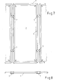
- Wie insbesondere
Figur 7 zu entnehmen ist, sind mehrere Flügel 1 der Sichtschutzeinrichtung untereinander mittels Scharniere bildenden als Verbindungsklipps 7 als Klammern schwenkbeweglich zueinander befestigt. Die Verbindungsklipps 7 sind aus Kunststoff ausgebildet und weisen zwei diametral gegenüberliegend angeordnete, etwa C-förmig ausgebildete Schnappaufnahmen 8 auf. Die Schnappaufnahmen 8 werden jeweils durch vier federelastisch ausgebildete Haltearme 9 der Verbindungsklipps 7 gebildet. Die Federelastizität derselben ergibt sich aus den Eigenschaften und der Dickenverteilung des thermoplastischen Materials. - Wie
Figur 7 zu entnehmen ist, ist der mittlere der drei dort dargestellten Flügel 1 der Sichtschutzeinrichtung jeweils beidseitig mit Verbindungsklipps 7 an einem benachbarten Flügel 1 befestigt. Die Verbindungsklipps 7 erlauben es, die Rahmenschenkel 10 benachbarter Rahmen 3 einfach miteinander zu verklipsen, wobei gleichzeitig die schwenkbewegliche Artikulation derselben gewährleistet ist. Dabei bildet jeweils ein Rahmenschenkel 10 eines Flügels 1 die Schwenkachse, um welche die Schwenkbewegung des benachbarten Flügels 1 vollzogen wird. - Damit die Schwenkachse jeweils eindeutig festliegt, ist jeweils ein Rahmenschenkel 10 in dem Verbindungsklipp 7 drehfest arretiert, und zwar durch Rastvorsprünge 11, die in entsprechende Rastvertiefungen 12 der Haltearme 9 eingreifen. Die Rastvorsprünge 11 können im einfachsten Fall durch die Köpfe von Zylinderschrauben gebildet werden, die durch den jeweiligen Rohrabschnitt 4 geführt sind.
- Zwischen den Haltearmen 9 der Verbindungsklipps 7 sind jeweils Schwenkbegrenzungsanschläge 17 vorgesehen, die mit den jeweils in gleicher Höhe der Rahmenschenkel 10 diametral gegenüberliegend angeordneten Rastvorsprüngen 11 im Sinne einer Arretierung von Verbindungsklipp 7 und Rahmenschenkel 10 zueinander zusammenwirken. Hierzu wird der betreffende Verbindungsklipp 7 so auf den Rahmenschenkel 10 aufgeschnappt, dass die Köpfe der die Rohrabschnitte 4 verbindenden Zylinderschraube sich zwischen zwei übereinanderliegend angeordneten Haltearmen 9 einfügen und dort gegen die Schwenkbegrenzungsanschläge 17 anliegen. Hierdurch wird nicht nur eine radiale Festlegung von Verbindungsklipp 7 und Rahmenschenkel 10 zueinander bewirkt, sondern auch eine axiale Sicherung derselben.
- Die Verbindungsklipps 7 sind jeweils im Bereich einer Schnappaufnahme 8, jedenfalls bei dem dargestellten Ausführungsbeispiel, mit einer Rastvertiefung 12 versehen, die jeweils im Tiefsten der C-förmig ausgebildeten Schnappaufnahme 8 angeordnet ist. Die Rastvertiefung 12 ist um 90° versetzt zu den gegenüberliegend angeordneten Schwenkbegrenzungsanschlägen 17 positioniert, so dass die Verbindungsklipps 7 in zwei um 90° Winkelabstand zueinander versetzt angeordneten Positionen festlegbar sind. Hierzu ist jeweils das Abnehmen des betreffenden Verbindungsklipps 7 von dem Rahmenschenkel 10 erforderlich.
- Die Rastvorsprünge 11 sind selbstverständlich in der dargestellten Konstellation auf einer Höhe des betreffenden Rahmenschenkels 11 angeordnet. Dies kann beispielsweise im Bereich einer ohnehin erforderlichen Verschraubung der Rohrabschnitte 4 miteinander sein. Hierdurch ist einerseits die Anordnung der Flügel 1 der Sichtschutzanordnung in einer Linie fluchtend zueinander möglich, andererseits kann ein Einfalten dieser in die in
Figur 11 gezeigte Lage bewerkstelligt werden, derart, dass Flügel 1 mit ihrer Außenkontur deckungsgleich bzw. fluchtend aufeinanderliegen. Hierzu ist es erforderlich, die Verbindungsklipps 7 jeweils in einer um 90° versetzten Winkelstellung zu arretieren, wie dies inFigur 10 an dem von einer andeutungsweise dargestellten Wand 13 abliegenden Ende der Sichtschutzeinrichtung dargestellt ist. - Es versteht sich von selbst, dass die Sichtschutzeinrichtung wahlweise zur Bodenbefestigung oder zur Wandbefestigung vorgesehen sein kann. Der in den
Figuren 2 und 5 dargestellte Flügel 1 der Sichtschutzeinrichtung ist zur Bodenaufstellung mit zwei Klippfüßen 14 versehen. Die Klippfüße 14 sind ebenfalls mit einer Schnappaufnahme versehen, die so ausgebildet ist, dass diese jeweils an einem sich vertikal erstreckenden Rahmenschenkel 10 eines Flügels 1 seitlich befestigbar sind und den in aufgestellter Lage jeweils unteren, sich jeweils horizontal erstreckenden Rahmenschenkel 10 im Bereich einer Ecke stützend untergreifen. Die Klippfüße 14 sind hierzu als einteilige Kunststoffelemente mit einem Sockelbereich 18 und einem einteilig angeformten Standrohr 19 versehen. Das Standrohr 19 hat, die Schnappaufnahme bildend, ein etwa C-förmiges Querschnittsprofil, und zwar nur über eine Teillänge, die auf den jeweils vertikalen Rahmenschenkel 10 eines Rahmens 3 aufgeschnappt wird. Der sich in Längsrichtung des Standrohrs 19 erstreckende Aufnahmeschlitz 20 erweitert sich hierzu in Richtung auf den Sockelbereich 18 des Fußklipps 14. In diesem Bereich bildet der Aufnahmeschlitz 20 eine Art Sackloch, in dem die untere Rahmenecke oder der untere Rahmenschenkel 10 des Rahmens 3 aufliegt. - Zur Wandmontage der Sichtschutzeinrichtung sind Wandklipps 7b vorgesehen, die ebenfalls eine Schnappaufnahme 8 ausbilden und den betreffenden Rahmenschenkel des an der Wand 13 zu montierenden Flügels 1 umgreifen. Die Ausbildung der Wandklipps 7b ist etwa entsprechend der Ausbildung der Verbindungsklipps 7. Die Wandklipps 7b sind jeweils mit einem Sockel versehen, der mit einer Schraube durchsetzt gegen die Wand 13 verdübelt wird.
- Durch die erfindungsgemäß vorgesehene Klipp-Technik lassen sich auch diverse Zubehör- und Umbauteile der Sichtschutzeinrichtung befestigen, wie es beispielsweise in
Figur 12 dargestellt ist. Dort ist mittels zweier Verbindungsklipps 7 ein Sonnenschirm 15 an einem Rahmenschenkel 10 eines Flügels 1 befestigt. Mit 16 ist inFigur 6 ein Erdspieß mit Schnappaufnahme bezeichnet, der eine Aufstellung der Sichtschutzeinrichtung auf weichem Untergrund ermöglicht. - Insgesamt wird durch die Schnappverbindung der Anbauteile und der Flügel 1 untereinander der Aufbau eines leichten und modularen Systems ermöglicht.
-
- 1
- Flügel
- 2
- Sichtschutzbespannung
- 3
- Rahmen
- 4
- Rohrabschnitte
- 5
- Schrauben
- 6
- Befestigungsmittel
- 7
- Verbindungsklipp
- 7b
- Wandklipp
- 8
- Schnappaufnahmen
- 9
- Haltearme
- 10
- Rahmenschenkel
- 11
- Rastvorsprünge
- 12
- Rastvertiefungen
- 13
- Wand
- 14
- Fußklipp
- 15
- Sonnenschirm
- 16
- Erdspieß
- 17
- Schwenkbegrenzungsanschläge
- 18
- Sockelbereich
- 19
- Standrohr
- 20
- Aufnahmeschlitz
Claims (11)
- Sichtschutzeinrichtung, umfassend wenigstens zwei schwenkbeweglich miteinander verbundene Flügel (1) als jeweils mit Sichtschutzbespannung (2) versehene Rahmen (3), von denen zwei sich etwa parallel zueinander erstreckende Rahmenschenkel (10) benachbarter Flügel (1) über jeweils mit dem betreffenden Rahmenschenkel (10) ein Scharnier bildende Klammern miteinander verbunden sind, wobei die Klammern jeweils mit wenigstens einem Rahmenschenkel (10) in wenigstens einer Winkelstellung eine formschlüssige Arretierung bilden.
- Einrichtung nach Anspruch 1, dadurch gekennzeichnet, dass die Klammern jeweils zwei etwa C-förmig ausgebildete Aufnahmen (8) für die Rahmenschenkel (10) aufweisen, die in montierter Lage diese umgreifen.
- Einrichtung nach Anspruch 1 oder 2, dadurch gekennzeichnet, dass die Schnappaufnahmen (8) jeweils durch federelastisch ausgebildete Halterarme (9) gebildet werden.
- Einrichtung nach einem der Ansprüche 1 bis 3, dadurch gekennzeichnet, dass die Klammern einstückig aus Kunststoff ausgebildet sind.
- Einrichtung nach Anspruch 3, dadurch gekennzeichnet, dass die Klammern wenigstens im Bereich einer Schnappaufnahme (8) mindestens eine Rastvertiefung (12) aufweisen, die mit Rastvorsprüngen (11) der Rahmenschenkel (10) zusammenwirken.
- Einrichtung nach einem der Ansprüche 3 oder 5, dadurch gekennzeichnet, dass wenigstens eine Schnappaufnahme (8) mit Schwenkbegrenzungsanschlägen (17) versehen ist, die mit den Rastvorsprüngen (11) eines Rahmenschenkels (10) zusammenwirken.
- Einrichtung nach Anspruch 5 oder 6, dadurch gekennzeichnet, dass an wenigstens einem Rahmenschenkel (10) wenigstens eines Flügels (1) jeweils zwei Rastvorsprünge (11) auf gleicher Höhe jeweils paarweise diametral gegenüberliegend angeordnet sind.
- Einrichtung nach Anspruch 7, dadurch gekennzeichnet, dass die Rahmen (3) Eckelemente aufweisen, über welche die Rahmenschenkel (10) zusammengefügt sind.
- Einrichtung nach einem der Ansprüche 1 bis 8, dadurch gekennzeichnet, dass die Rahmen (3) der Flügel (1) aus mehreren die Rahmenschenkel (10) bildenden Rohren oder Stangen zusammengesetzt ist.
- Einrichtung nach einem der Ansprüche 1 bis 7, dadurch gekennzeichnet, dass an wenigstens einem Flügel (1) Klammern (7b) zur Wandbefestigung vorgesehen sind, die jeweils einen mit Befestigungsmitteln versehenen Sockel und eine etwa C-förmig ausgebildete, den Rahmenschenkel (10) umschließende Schnappaufnahme (8) aufweisen.
- Sichtschutzeinrichtung, umfassend wenigstens einen Flügel (1) als mit Sichtschutzbespannung (2) versehener Rahmen (3), der mittels ein Scharnier bildenden Klammer an einer Wand befestigbar ist.
Applications Claiming Priority (2)
| Application Number | Priority Date | Filing Date | Title |
|---|---|---|---|
| DE20211079U DE20211079U1 (de) | 2002-07-22 | 2002-07-22 | Sichtschutzeinrichtung |
| EP03013918A EP1384832B1 (de) | 2002-07-22 | 2003-06-20 | Sichtschutzeinrichtung |
Related Parent Applications (2)
| Application Number | Title | Priority Date | Filing Date |
|---|---|---|---|
| EP03013918.2 Division | 2003-06-20 | ||
| EP03013918A Division EP1384832B1 (de) | 2002-07-22 | 2003-06-20 | Sichtschutzeinrichtung |
Publications (3)
| Publication Number | Publication Date |
|---|---|
| EP2014844A1 true EP2014844A1 (de) | 2009-01-14 |
| EP2014844B1 EP2014844B1 (de) | 2013-04-03 |
| EP2014844B9 EP2014844B9 (de) | 2013-07-03 |
Family
ID=7973273
Family Applications (2)
| Application Number | Title | Priority Date | Filing Date |
|---|---|---|---|
| EP08018439.3A Expired - Lifetime EP2014844B9 (de) | 2002-07-22 | 2003-06-20 | Sichtschutzeinrichtung |
| EP03013918A Expired - Lifetime EP1384832B1 (de) | 2002-07-22 | 2003-06-20 | Sichtschutzeinrichtung |
Family Applications After (1)
| Application Number | Title | Priority Date | Filing Date |
|---|---|---|---|
| EP03013918A Expired - Lifetime EP1384832B1 (de) | 2002-07-22 | 2003-06-20 | Sichtschutzeinrichtung |
Country Status (4)
| Country | Link |
|---|---|
| EP (2) | EP2014844B9 (de) |
| AT (1) | ATE431880T1 (de) |
| DE (2) | DE20211079U1 (de) |
| ES (1) | ES2327400T3 (de) |
Cited By (3)
| Publication number | Priority date | Publication date | Assignee | Title |
|---|---|---|---|---|
| WO2012007897A1 (en) * | 2010-07-12 | 2012-01-19 | Necdet Suat Mehmetoglu | Folding balcony screen |
| FR3022576A1 (fr) * | 2014-06-20 | 2015-12-25 | Creations Mathou Jean Pierre | Barriere a panneaux repliables |
| CN113616053A (zh) * | 2021-07-28 | 2021-11-09 | 南通市第一人民医院 | 一种重症监护室用具有负压功能的防感染隔帘 |
Families Citing this family (4)
| Publication number | Priority date | Publication date | Assignee | Title |
|---|---|---|---|---|
| DE202007008133U1 (de) | 2007-06-06 | 2007-09-20 | Peddy Shield Sonnenschutzsysteme Gmbh | Erdspieß mit angeschraubtem Rohr als Aufstellvariante Clip-Paravent |
| DE202011102324U1 (de) | 2011-06-20 | 2011-11-10 | Peddy Shield Sonnenschutzsysteme Gmbh | Sichtschutz- und/oder Windschutzeinrichtung |
| DE202015103524U1 (de) | 2015-07-03 | 2016-10-13 | M.A.C.'s Holding Gmbh | Paravent |
| CN112726826A (zh) * | 2019-10-28 | 2021-04-30 | 佛山市南海区品位智能家具有限公司 | 一种足球阳光房及其安装方法 |
Citations (5)
| Publication number | Priority date | Publication date | Assignee | Title |
|---|---|---|---|---|
| US4134439A (en) * | 1977-06-22 | 1979-01-16 | Commercial Vehicle Parts, Inc. | Portable industrial screen |
| US4715072A (en) * | 1985-03-18 | 1987-12-29 | Sudmann Jurgen Peter | Shower barrier |
| US4774792A (en) * | 1986-08-25 | 1988-10-04 | Ballance Design Limited | Exhibition display apparatus |
| US5722477A (en) | 1995-10-31 | 1998-03-03 | The Children's Factory | Pipe connector assembly with internal locking mechanism |
| US6206079B1 (en) * | 1998-11-30 | 2001-03-27 | Industrial Noise Control, Inc. | Curtain barrier assembly |
-
2002
- 2002-07-22 DE DE20211079U patent/DE20211079U1/de not_active Expired - Lifetime
-
2003
- 2003-06-20 EP EP08018439.3A patent/EP2014844B9/de not_active Expired - Lifetime
- 2003-06-20 DE DE50311530T patent/DE50311530D1/de not_active Expired - Lifetime
- 2003-06-20 EP EP03013918A patent/EP1384832B1/de not_active Expired - Lifetime
- 2003-06-20 AT AT03013918T patent/ATE431880T1/de active
- 2003-06-20 ES ES03013918T patent/ES2327400T3/es not_active Expired - Lifetime
Patent Citations (5)
| Publication number | Priority date | Publication date | Assignee | Title |
|---|---|---|---|---|
| US4134439A (en) * | 1977-06-22 | 1979-01-16 | Commercial Vehicle Parts, Inc. | Portable industrial screen |
| US4715072A (en) * | 1985-03-18 | 1987-12-29 | Sudmann Jurgen Peter | Shower barrier |
| US4774792A (en) * | 1986-08-25 | 1988-10-04 | Ballance Design Limited | Exhibition display apparatus |
| US5722477A (en) | 1995-10-31 | 1998-03-03 | The Children's Factory | Pipe connector assembly with internal locking mechanism |
| US6206079B1 (en) * | 1998-11-30 | 2001-03-27 | Industrial Noise Control, Inc. | Curtain barrier assembly |
Cited By (3)
| Publication number | Priority date | Publication date | Assignee | Title |
|---|---|---|---|---|
| WO2012007897A1 (en) * | 2010-07-12 | 2012-01-19 | Necdet Suat Mehmetoglu | Folding balcony screen |
| FR3022576A1 (fr) * | 2014-06-20 | 2015-12-25 | Creations Mathou Jean Pierre | Barriere a panneaux repliables |
| CN113616053A (zh) * | 2021-07-28 | 2021-11-09 | 南通市第一人民医院 | 一种重症监护室用具有负压功能的防感染隔帘 |
Also Published As
| Publication number | Publication date |
|---|---|
| EP1384832A2 (de) | 2004-01-28 |
| ATE431880T1 (de) | 2009-06-15 |
| DE50311530D1 (de) | 2009-07-02 |
| EP2014844B1 (de) | 2013-04-03 |
| DE20211079U1 (de) | 2002-09-26 |
| EP2014844B9 (de) | 2013-07-03 |
| EP1384832A3 (de) | 2004-11-17 |
| EP1384832B1 (de) | 2009-05-20 |
| ES2327400T3 (es) | 2009-10-29 |
Similar Documents
| Publication | Publication Date | Title |
|---|---|---|
| DE10338816B3 (de) | Halterung für eine Platte, insbesondere für eine Glasscheibe | |
| DE202004000706U1 (de) | Profilschienensystem zur Überprüfung von Bodenbelagsübergängen | |
| EP2014844B9 (de) | Sichtschutzeinrichtung | |
| EP1849929A2 (de) | Freitragendes Vordach | |
| DE102020100493A1 (de) | Torpfosten für Sichtschutz | |
| DE10163807A1 (de) | Befestigungsvorrichtung | |
| DE4403827A1 (de) | Bauelementesatz für eine Einfriedung, Verblendung oder Vertäfelung | |
| EP1541776B1 (de) | Befestigungsprofil | |
| DE102018005072A1 (de) | Befestigungselement zur Montage einer Fassadenpaneele | |
| DE102016213394B4 (de) | Schutzvorrichtung, insbesondere als Insektenschutz | |
| CH669832A5 (en) | Supporting structure for light fittings - uses hollow rails with clips and supports inserted into longitudinal grooves for wall and ceiling mounting | |
| DE102019102278B4 (de) | Unterbauanordnung für eine Unterkonstruktion einer Terrasse oder eines sonstigen Bodens | |
| DE8417333U1 (de) | Abhaenge-vorrichtung fuer c-foermige tragschienen von unterdecken od. dgl. | |
| DE102023000634A1 (de) | Geländertragprofil | |
| DE9420155U1 (de) | FAssadenbekleidung mit horizontalen Halteprofilen | |
| EP4417767A1 (de) | Geländertragprofil | |
| DE102023000633A1 (de) | Geländerhalteprofil | |
| DE19807387C2 (de) | Profilhalter für die Wand- und/oder Bodenbefestigung von Ständersystemen | |
| EP4417766A1 (de) | Geländerhalteprofil | |
| DE102023005516A1 (de) | Statikkonsole und Halteeinrichtung zum Einbau in einen Rollladenkasten oder in einen Raffstorekasten | |
| DE102023125050A1 (de) | Statikkonsole und Halteeinrichtung zum Einbau in einen Rollladenkasten oder in einen Raffstorekasten | |
| CH645425A5 (en) | Awning | |
| AT503243B1 (de) | Sockelleiste | |
| DE202023105379U1 (de) | Statikkonsole und Halteeinrichtung zum Einbau in einen Rolladenkasten oder in einen Raffstorekasten | |
| DE9413193U1 (de) | Stützenhalter für die Halterung einer vorzugsweise rohrförmigen Bodenstütze eines Balkons |
Legal Events
| Date | Code | Title | Description |
|---|---|---|---|
| PUAI | Public reference made under article 153(3) epc to a published international application that has entered the european phase |
Free format text: ORIGINAL CODE: 0009012 |
|
| AC | Divisional application: reference to earlier application |
Ref document number: 1384832 Country of ref document: EP Kind code of ref document: P |
|
| AK | Designated contracting states |
Kind code of ref document: A1 Designated state(s): AT BE BG CH CY CZ DE DK EE ES FI FR GB GR HU IE IT LI LU MC NL PT RO SE SI SK TR |
|
| AX | Request for extension of the european patent |
Extension state: AL LT LV MK |
|
| 17P | Request for examination filed |
Effective date: 20090604 |
|
| AKX | Designation fees paid |
Designated state(s): AT BE BG CH CY CZ DE DK EE ES FI FR GB GR HU IE IT LI LU MC NL PT RO SE SI SK TR |
|
| 17Q | First examination report despatched |
Effective date: 20100819 |
|
| GRAP | Despatch of communication of intention to grant a patent |
Free format text: ORIGINAL CODE: EPIDOSNIGR1 |
|
| GRAS | Grant fee paid |
Free format text: ORIGINAL CODE: EPIDOSNIGR3 |
|
| GRAA | (expected) grant |
Free format text: ORIGINAL CODE: 0009210 |
|
| AC | Divisional application: reference to earlier application |
Ref document number: 1384832 Country of ref document: EP Kind code of ref document: P |
|
| AK | Designated contracting states |
Kind code of ref document: B1 Designated state(s): AT BE BG CH CY CZ DE DK EE ES FI FR GB GR HU IE IT LI LU MC NL PT RO SE SI SK TR |
|
| REG | Reference to a national code |
Ref country code: GB Ref legal event code: FG4D Free format text: NOT ENGLISH |
|
| REG | Reference to a national code |
Ref country code: AT Ref legal event code: REF Ref document number: 604844 Country of ref document: AT Kind code of ref document: T Effective date: 20130415 Ref country code: CH Ref legal event code: EP |
|
| REG | Reference to a national code |
Ref country code: CH Ref legal event code: NV Representative=s name: FIAMMENGHI-FIAMMENGHI, CH |
|
| REG | Reference to a national code |
Ref country code: IE Ref legal event code: FG4D Free format text: LANGUAGE OF EP DOCUMENT: GERMAN |
|
| REG | Reference to a national code |
Ref country code: DE Ref legal event code: R096 Ref document number: 50314748 Country of ref document: DE Effective date: 20130529 |
|
| PGFP | Annual fee paid to national office [announced via postgrant information from national office to epo] |
Ref country code: GB Payment date: 20130619 Year of fee payment: 11 |
|
| PG25 | Lapsed in a contracting state [announced via postgrant information from national office to epo] |
Ref country code: SI Free format text: LAPSE BECAUSE OF FAILURE TO SUBMIT A TRANSLATION OF THE DESCRIPTION OR TO PAY THE FEE WITHIN THE PRESCRIBED TIME-LIMIT Effective date: 20130403 |
|
| REG | Reference to a national code |
Ref country code: NL Ref legal event code: VDEP Effective date: 20130403 |
|
| PG25 | Lapsed in a contracting state [announced via postgrant information from national office to epo] |
Ref country code: SE Free format text: LAPSE BECAUSE OF FAILURE TO SUBMIT A TRANSLATION OF THE DESCRIPTION OR TO PAY THE FEE WITHIN THE PRESCRIBED TIME-LIMIT Effective date: 20130403 Ref country code: GR Free format text: LAPSE BECAUSE OF FAILURE TO SUBMIT A TRANSLATION OF THE DESCRIPTION OR TO PAY THE FEE WITHIN THE PRESCRIBED TIME-LIMIT Effective date: 20130704 Ref country code: PT Free format text: LAPSE BECAUSE OF FAILURE TO SUBMIT A TRANSLATION OF THE DESCRIPTION OR TO PAY THE FEE WITHIN THE PRESCRIBED TIME-LIMIT Effective date: 20130805 Ref country code: NL Free format text: LAPSE BECAUSE OF FAILURE TO SUBMIT A TRANSLATION OF THE DESCRIPTION OR TO PAY THE FEE WITHIN THE PRESCRIBED TIME-LIMIT Effective date: 20130403 Ref country code: ES Free format text: LAPSE BECAUSE OF FAILURE TO SUBMIT A TRANSLATION OF THE DESCRIPTION OR TO PAY THE FEE WITHIN THE PRESCRIBED TIME-LIMIT Effective date: 20130714 Ref country code: FI Free format text: LAPSE BECAUSE OF FAILURE TO SUBMIT A TRANSLATION OF THE DESCRIPTION OR TO PAY THE FEE WITHIN THE PRESCRIBED TIME-LIMIT Effective date: 20130403 |
|
| PG25 | Lapsed in a contracting state [announced via postgrant information from national office to epo] |
Ref country code: BG Free format text: LAPSE BECAUSE OF FAILURE TO SUBMIT A TRANSLATION OF THE DESCRIPTION OR TO PAY THE FEE WITHIN THE PRESCRIBED TIME-LIMIT Effective date: 20130703 Ref country code: CY Free format text: LAPSE BECAUSE OF FAILURE TO SUBMIT A TRANSLATION OF THE DESCRIPTION OR TO PAY THE FEE WITHIN THE PRESCRIBED TIME-LIMIT Effective date: 20130403 |
|
| BERE | Be: lapsed |
Owner name: MULLER-PEDDINGHAUS, REINER, PROF. DR. Effective date: 20130630 |
|
| PG25 | Lapsed in a contracting state [announced via postgrant information from national office to epo] |
Ref country code: MC Free format text: LAPSE BECAUSE OF FAILURE TO SUBMIT A TRANSLATION OF THE DESCRIPTION OR TO PAY THE FEE WITHIN THE PRESCRIBED TIME-LIMIT Effective date: 20130403 Ref country code: CZ Free format text: LAPSE BECAUSE OF FAILURE TO SUBMIT A TRANSLATION OF THE DESCRIPTION OR TO PAY THE FEE WITHIN THE PRESCRIBED TIME-LIMIT Effective date: 20130403 Ref country code: EE Free format text: LAPSE BECAUSE OF FAILURE TO SUBMIT A TRANSLATION OF THE DESCRIPTION OR TO PAY THE FEE WITHIN THE PRESCRIBED TIME-LIMIT Effective date: 20130403 Ref country code: SK Free format text: LAPSE BECAUSE OF FAILURE TO SUBMIT A TRANSLATION OF THE DESCRIPTION OR TO PAY THE FEE WITHIN THE PRESCRIBED TIME-LIMIT Effective date: 20130403 Ref country code: DK Free format text: LAPSE BECAUSE OF FAILURE TO SUBMIT A TRANSLATION OF THE DESCRIPTION OR TO PAY THE FEE WITHIN THE PRESCRIBED TIME-LIMIT Effective date: 20130403 |
|
| PLBE | No opposition filed within time limit |
Free format text: ORIGINAL CODE: 0009261 |
|
| STAA | Information on the status of an ep patent application or granted ep patent |
Free format text: STATUS: NO OPPOSITION FILED WITHIN TIME LIMIT |
|
| PG25 | Lapsed in a contracting state [announced via postgrant information from national office to epo] |
Ref country code: IT Free format text: LAPSE BECAUSE OF FAILURE TO SUBMIT A TRANSLATION OF THE DESCRIPTION OR TO PAY THE FEE WITHIN THE PRESCRIBED TIME-LIMIT Effective date: 20130403 Ref country code: RO Free format text: LAPSE BECAUSE OF FAILURE TO SUBMIT A TRANSLATION OF THE DESCRIPTION OR TO PAY THE FEE WITHIN THE PRESCRIBED TIME-LIMIT Effective date: 20130403 |
|
| 26N | No opposition filed |
Effective date: 20140106 |
|
| REG | Reference to a national code |
Ref country code: IE Ref legal event code: MM4A |
|
| PG25 | Lapsed in a contracting state [announced via postgrant information from national office to epo] |
Ref country code: BE Free format text: LAPSE BECAUSE OF NON-PAYMENT OF DUE FEES Effective date: 20130630 |
|
| REG | Reference to a national code |
Ref country code: DE Ref legal event code: R097 Ref document number: 50314748 Country of ref document: DE Effective date: 20140106 |
|
| PG25 | Lapsed in a contracting state [announced via postgrant information from national office to epo] |
Ref country code: IE Free format text: LAPSE BECAUSE OF NON-PAYMENT OF DUE FEES Effective date: 20130620 |
|
| REG | Reference to a national code |
Ref country code: DE Ref legal event code: R082 Ref document number: 50314748 Country of ref document: DE Representative=s name: KIERDORF RITSCHEL PATENTANWAELTE PARTG MBB, DE Ref country code: DE Ref legal event code: R082 Ref document number: 50314748 Country of ref document: DE Representative=s name: KIERDORF RITSCHEL RICHLY PATENTANWAELTE PARTG , DE Ref country code: DE Ref legal event code: R082 Ref document number: 50314748 Country of ref document: DE Representative=s name: RICHLY & RITSCHEL PATENTANWAELTE PARTG MBB, DE |
|
| GBPC | Gb: european patent ceased through non-payment of renewal fee |
Effective date: 20140620 |
|
| PG25 | Lapsed in a contracting state [announced via postgrant information from national office to epo] |
Ref country code: GB Free format text: LAPSE BECAUSE OF NON-PAYMENT OF DUE FEES Effective date: 20140620 |
|
| REG | Reference to a national code |
Ref country code: FR Ref legal event code: PLFP Year of fee payment: 13 |
|
| PG25 | Lapsed in a contracting state [announced via postgrant information from national office to epo] |
Ref country code: TR Free format text: LAPSE BECAUSE OF FAILURE TO SUBMIT A TRANSLATION OF THE DESCRIPTION OR TO PAY THE FEE WITHIN THE PRESCRIBED TIME-LIMIT Effective date: 20130403 |
|
| PG25 | Lapsed in a contracting state [announced via postgrant information from national office to epo] |
Ref country code: HU Free format text: LAPSE BECAUSE OF FAILURE TO SUBMIT A TRANSLATION OF THE DESCRIPTION OR TO PAY THE FEE WITHIN THE PRESCRIBED TIME-LIMIT; INVALID AB INITIO Effective date: 20030620 Ref country code: LU Free format text: LAPSE BECAUSE OF NON-PAYMENT OF DUE FEES Effective date: 20130620 |
|
| REG | Reference to a national code |
Ref country code: FR Ref legal event code: PLFP Year of fee payment: 14 |
|
| REG | Reference to a national code |
Ref country code: DE Ref legal event code: R082 Ref document number: 50314748 Country of ref document: DE Representative=s name: KIERDORF RITSCHEL RICHLY PATENTANWAELTE PARTG , DE Ref country code: DE Ref legal event code: R081 Ref document number: 50314748 Country of ref document: DE Owner name: PEDDY SHIELD SONNENSCHUTZSYSTEME GMBH, DE Free format text: FORMER OWNER: MUELLER-PEDDINGHAUS, REINER, PROF. DR., 51467 BERGISCH GLADBACH, DE Ref country code: DE Ref legal event code: R082 Ref document number: 50314748 Country of ref document: DE Representative=s name: RICHLY & RITSCHEL PATENTANWAELTE PARTG MBB, DE |
|
| PGFP | Annual fee paid to national office [announced via postgrant information from national office to epo] |
Ref country code: CH Payment date: 20160620 Year of fee payment: 14 |
|
| PGFP | Annual fee paid to national office [announced via postgrant information from national office to epo] |
Ref country code: AT Payment date: 20160621 Year of fee payment: 14 Ref country code: FR Payment date: 20160627 Year of fee payment: 14 |
|
| REG | Reference to a national code |
Ref country code: CH Ref legal event code: PUE Owner name: PEDDY SHIELD SONNENSCHUTZSYSTEME GMBH, DE Free format text: FORMER OWNER: MUELLER-PEDDINGHAUS, REINER, PROF. DR., DE |
|
| REG | Reference to a national code |
Ref country code: FR Ref legal event code: TP Owner name: PEDDY SHIELD SONNENSCHUTZSYSTEME GMBH, DE Effective date: 20161215 |
|
| REG | Reference to a national code |
Ref country code: AT Ref legal event code: PC Ref document number: 604844 Country of ref document: AT Kind code of ref document: T Owner name: PEDDY SHIELD SONNENSCHUTZSYSTEME GMBH, DE Effective date: 20170411 |
|
| REG | Reference to a national code |
Ref country code: CH Ref legal event code: PL |
|
| REG | Reference to a national code |
Ref country code: AT Ref legal event code: MM01 Ref document number: 604844 Country of ref document: AT Kind code of ref document: T Effective date: 20170620 |
|
| REG | Reference to a national code |
Ref country code: FR Ref legal event code: ST Effective date: 20180228 |
|
| PG25 | Lapsed in a contracting state [announced via postgrant information from national office to epo] |
Ref country code: CH Free format text: LAPSE BECAUSE OF NON-PAYMENT OF DUE FEES Effective date: 20170630 Ref country code: LI Free format text: LAPSE BECAUSE OF NON-PAYMENT OF DUE FEES Effective date: 20170630 |
|
| PG25 | Lapsed in a contracting state [announced via postgrant information from national office to epo] |
Ref country code: AT Free format text: LAPSE BECAUSE OF NON-PAYMENT OF DUE FEES Effective date: 20170620 Ref country code: FR Free format text: LAPSE BECAUSE OF NON-PAYMENT OF DUE FEES Effective date: 20170630 |
|
| PGFP | Annual fee paid to national office [announced via postgrant information from national office to epo] |
Ref country code: DE Payment date: 20180606 Year of fee payment: 16 |
|
| REG | Reference to a national code |
Ref country code: DE Ref legal event code: R119 Ref document number: 50314748 Country of ref document: DE |
|
| PG25 | Lapsed in a contracting state [announced via postgrant information from national office to epo] |
Ref country code: DE Free format text: LAPSE BECAUSE OF NON-PAYMENT OF DUE FEES Effective date: 20200101 |