EP2014864B1 - Rollladen mit einer Anschlagvorrichtung zur Begrenzung der Aufrollung des Rollladenpanzers in den Rollladenkasten - Google Patents
Rollladen mit einer Anschlagvorrichtung zur Begrenzung der Aufrollung des Rollladenpanzers in den Rollladenkasten Download PDFInfo
- Publication number
- EP2014864B1 EP2014864B1 EP08352014A EP08352014A EP2014864B1 EP 2014864 B1 EP2014864 B1 EP 2014864B1 EP 08352014 A EP08352014 A EP 08352014A EP 08352014 A EP08352014 A EP 08352014A EP 2014864 B1 EP2014864 B1 EP 2014864B1
- Authority
- EP
- European Patent Office
- Prior art keywords
- limit stop
- activation means
- roller shutter
- shutter
- branches
- Prior art date
- Legal status (The legal status is an assumption and is not a legal conclusion. Google has not performed a legal analysis and makes no representation as to the accuracy of the status listed.)
- Active
Links
Images



Classifications
-
- E—FIXED CONSTRUCTIONS
- E06—DOORS, WINDOWS, SHUTTERS, OR ROLLER BLINDS IN GENERAL; LADDERS
- E06B—FIXED OR MOVABLE CLOSURES FOR OPENINGS IN BUILDINGS, VEHICLES, FENCES OR LIKE ENCLOSURES IN GENERAL, e.g. DOORS, WINDOWS, BLINDS, GATES
- E06B9/00—Screening or protective devices for wall or similar openings, with or without operating or securing mechanisms; Closures of similar construction
- E06B9/56—Operating, guiding or securing devices or arrangements for roll-type closures; Spring drums; Tape drums; Counterweighting arrangements therefor
- E06B9/80—Safety measures against dropping or unauthorised opening; Braking or immobilising devices; Devices for limiting unrolling
- E06B9/82—Safety measures against dropping or unauthorised opening; Braking or immobilising devices; Devices for limiting unrolling automatic
- E06B9/88—Safety measures against dropping or unauthorised opening; Braking or immobilising devices; Devices for limiting unrolling automatic for limiting unrolling
-
- E—FIXED CONSTRUCTIONS
- E06—DOORS, WINDOWS, SHUTTERS, OR ROLLER BLINDS IN GENERAL; LADDERS
- E06B—FIXED OR MOVABLE CLOSURES FOR OPENINGS IN BUILDINGS, VEHICLES, FENCES OR LIKE ENCLOSURES IN GENERAL, e.g. DOORS, WINDOWS, BLINDS, GATES
- E06B9/00—Screening or protective devices for wall or similar openings, with or without operating or securing mechanisms; Closures of similar construction
- E06B9/02—Shutters, movable grilles, or other safety closing devices, e.g. against burglary
- E06B9/08—Roll-type closures
- E06B9/11—Roller shutters
- E06B9/17—Parts or details of roller shutters, e.g. suspension devices, shutter boxes, wicket doors, ventilation openings
- E06B9/17046—Bottom bars
-
- E—FIXED CONSTRUCTIONS
- E06—DOORS, WINDOWS, SHUTTERS, OR ROLLER BLINDS IN GENERAL; LADDERS
- E06B—FIXED OR MOVABLE CLOSURES FOR OPENINGS IN BUILDINGS, VEHICLES, FENCES OR LIKE ENCLOSURES IN GENERAL, e.g. DOORS, WINDOWS, BLINDS, GATES
- E06B9/00—Screening or protective devices for wall or similar openings, with or without operating or securing mechanisms; Closures of similar construction
- E06B9/02—Shutters, movable grilles, or other safety closing devices, e.g. against burglary
- E06B9/08—Roll-type closures
- E06B9/11—Roller shutters
- E06B9/15—Roller shutters with closing members formed of slats or the like
- E06B2009/1577—Slat end pieces used for guiding shutter
- E06B2009/1583—Slat end pieces used for guiding shutter inserted in slat cavity
-
- E—FIXED CONSTRUCTIONS
- E06—DOORS, WINDOWS, SHUTTERS, OR ROLLER BLINDS IN GENERAL; LADDERS
- E06B—FIXED OR MOVABLE CLOSURES FOR OPENINGS IN BUILDINGS, VEHICLES, FENCES OR LIKE ENCLOSURES IN GENERAL, e.g. DOORS, WINDOWS, BLINDS, GATES
- E06B9/00—Screening or protective devices for wall or similar openings, with or without operating or securing mechanisms; Closures of similar construction
- E06B9/56—Operating, guiding or securing devices or arrangements for roll-type closures; Spring drums; Tape drums; Counterweighting arrangements therefor
- E06B9/80—Safety measures against dropping or unauthorised opening; Braking or immobilising devices; Devices for limiting unrolling
- E06B9/82—Safety measures against dropping or unauthorised opening; Braking or immobilising devices; Devices for limiting unrolling automatic
- E06B9/88—Safety measures against dropping or unauthorised opening; Braking or immobilising devices; Devices for limiting unrolling automatic for limiting unrolling
- E06B2009/885—Braking mechanism activated by the bottom bar
Definitions
- the present invention relates to the field of construction, more particularly to a roller shutter intended to be mounted in an opening made in a building or the like, according to the preamble of claim 1.
- tulip means for the present invention any device facilitating the introduction of the apron into the guide rails and having means for supporting the stop of the roller shutter in the direction of the winding of the deck in the trunk and in to limit this winding.
- a rolling shutter of this type is known with the document DE 296 11 369 , comprising two flexible stops respectively mounted at each lateral end of the last deck blade.
- the V-shaped flexible stops the opening of the V being turned upwards, allow the automatic crossing of the tulips in the direction of the unwinding of the deck, by elastic compression of the branches of the V towards each other, and prevent the crossing of the tulips in the opposite direction of winding apron because the branches of the V resume under the effect of their elasticity their initial position.
- Such a shutter stop technology works pretty well, but has a disadvantage with respect to the disassembly of the apron: indeed, it is necessary in this case to use a suitable tool to reach the branches of the V inside the guide rails in an inaccessible place in the upper part of the opening, and compress them to allow the apron to cross the tulips in the direction of winding.
- a roller shutter is in principle provided with two stops respectively placed at each end of the last deck blade, the operation is to be repeated twice and at two different locations making disassembly of the apron even more delicate.
- the need for a compression of the elastic branches of the V induces an effort for the crossing of the tulips in the direction of the unfolding of the deck, an effort that can actually turn into a blocking of the deck if it is too important compared to the unwinding force of the deck, all the weaker at this time that almost the entire deck is wrapped in the trunk and that the weight of the deck then plays very little.
- DE 102 58 374 which relates to an abutment device for limiting the winding of the apron in a roller shutter box, comprising an abutment adopting a rigid T-shape having an extension intended to slide inside a shutter blade, the abutment being movable as a whole in longitudinal translation in the profile defining the last blade of the shutter.
- the stop can thus adopt two positions as follows: a first position in which the T is partially retracted inside the blade having a recess for this purpose so that it can not serve as a stop in the direction of winding roller shutter, and a second position in which the T is moved outwardly of the blade so that it can be arranged opposite the tulip and thus serve as a stop in the winding direction of the rolling shutter.
- the device comprises a return spring for blocking the entire stop in the second position.
- Such a rigid stop device loses the advantages of a stop with flexible branches.
- the document is still known DE 1,266,476 which relates to an articulated angle shutter device for roller shutter, comprising two rigid branches, a first abutment leg or movable branch, rotatable acting as a stop or abutment, and a second branch or fixed branch, adapted to be rigidly attached to the shutter rolling and supporting the rotating mobile branch.
- a rotation of 90 ° of the movable arm allows to put the latter in support on rigid advances integral fixed branch, thereby constituting an active position of the stop.
- the movable branch comprises a flexible blade which, in this active position, is clipped into a housing made in the fixed branch of the stop, to lock the active position of the movable arm. In the inactive position, the two branches of the abutment are aligned in the same plane.
- Such a rigid stop device loses the advantages of a stop with flexible branches.
- EP 0 092 122 which relates to a rolling shutter stop, mounted at the end of the blade, T-shaped, and rotatable along an axis of rotation parallel to the longitudinal axis of the blade corresponding to the main leg of the T, so that, according to two positions at 90 ° to one another, the stop blocks the winding of the flap or authorizes it.
- the device further comprises a system of spring and balls engaged with notches on the stop, to index the two positions.
- An alternative embodiment of the abutment according to this document is to move the stop T in translation along the longitudinal axis of the shutter blade. Such a rigid stop device loses the advantages of a stop with flexible branches.
- the present invention proposes to overcome these disadvantages, and to provide other advantages. More specifically, it consists of a roller shutter as defined at the beginning of the memory, wherein: said at least one stop comprises two flexible branches between which said activation means are movably arranged in translation, in at least one position of rest allowing a rimpedement of the flexible branches one towards the other corresponding to said rest position of the stop, and an active position allowing a separation of the flexible branches under the effect of a deformation of at least one of said two flexible branches corresponding to said active position of the stop.
- the present invention provides a stop with two positions, a rest position in which the crossing of the tulip is free in both directions of movement of the deck, that is to say it does not oppose any active resistance, except for a natural resistance of friction or sliding, and an active position in which the crossing in the opposite direction of the tulip is no longer possible, this position being advantageously used after the stop has passed the tulip in the direction of the unfolding of the apron ; the presence of two flexible branches between which said activation means are arranged, allows cooperation of the flexibility of the flexible branches of the stop with the activation means to establish the two positions of the stop.
- Such cooperation provides a stop with flexible branches, reinforced in that the activation means are adapted to be inserted between the branches defining the stop, thus able to define an abutment by obstacle, while allowing thanks to the flexibility of the branches, for example the possibilities of automatic return of the flexible branches of the stop in the rest position under the effect of the elasticity of these branches.
- Activation of the stop may be performed manually by an operator, or advantageously automatically according to a feature of the invention detailed below.
- the roller shutter according to the invention comprises means for guiding in translation of said activation means in a direction parallel to said lateral guide rails.
- This feature makes it possible to use the movement of the apron in the guide rails to automatically maneuver the activation means.
- said two flexible branches of the abutment adopt a shape of V whose longitudinal axis is parallel to said guide rails and whose opening of the flexible branches is turned downwards of said opening made in a building or similar.
- This characteristic allows a practical access of the activation means when they are arranged between the branches of the V, or manually by an operator because the opening of the V is directed towards the operator thus having a direct access to the activation means, either automatically as detailed below.
- said activation means comprise a movable element capable of coming into contact with the bottom of said opening made in a building or the like, said movable element being able to pass from the rest position to the active position when the hinged blade apron comes to bear at the bottom of said opening made in a building or the like.
- This feature allows an automatic activation of the activation means in the active position, by moving the apron which actuates the activation means during the end of its course when it arrives at low support, on the bottom of the opening or any other means of support low.
- This characteristic specifies a particularly advantageous mode of cooperation between a mobile element of the activation means and the flexible branches. V-shaped abutment, to obtain the two defined positions, rest and active.
- the shutter according to the invention comprises means for locking said activation means in the activated position.
- This feature ensures the maintenance of the activation means in the active position to ensure the active operation of the stop.
- the shutter according to the invention comprises means for unlocking said activation means, in order to allow the latter to pass from the active position to the rest position.
- This feature allows easy disassembly of the deck by placing in the rest position of the stop, allowing a crossing of the tulip without additional effort.
- the roller shutter according to the invention comprises means for driving said two flexible branches of the stop, to bring them closer to each other when said activation means pass from the active position to the position rest.
- This feature makes it possible to overcome a loosening of the elasticity of the flexible branches over time, by guaranteeing a return of the branches to the rest position even if these branches tend to remain in their active position despite the displacement of the activation means. rest position.
- the roller shutter according to the invention comprises means for connecting said activation means to said stop in the rest position, so that said activation means remain integral with it regardless of the adopted, resting or active position.
- This feature makes it possible to provide a compact and complete stop assembly, constituting a functional whole, and makes it possible to avoid, for example, the loss of an element of the assembly, in particular the loss of the activation means.
- said drive means and said connecting means are combined, and take the form of two lugs or pins respectively integral with said activation means or flexible branches.
- This feature is a particularly advantageous embodiment of the drive means and the connecting means combined.
- the roller blind according to the invention comprises means for embedding, in the lateral end of a blade of said apron, said abutment and said integral actuating means so as to form a blade tip.
- This feature allows quick and easy mounting of the stop in the appropriate deck blade, particularly the last blade that comes into contact with the bottom of the opening.
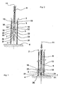
- a stop 3 preferably comprises two flexible branches 10 advantageously adopting a shape of V whose longitudinal axis 11 is parallel to the guide rails 1, and whose opening 12 of the flexible branches 10 is turned downwards 4 of the opening carried out in a building or the like; the activation means 7 are advantageously arranged between the two flexible branches 10.
- the V-shaped abutment 3 is advantageously fixed on the outer face of a plate 13 serving as a tip of the end of the blade on which the abutment 3 is mounted; in order to rigidly fix the abutment 3 at the end of a blade of the apron 6, embedding means 14 are arranged on the face of the plate 13 opposite to that on which the V-stop is fixed, as shown in FIGS. figures 5 or 7 .
- embedding means 14 are arranged on the face of the plate 13 opposite to that on which the V-stop is fixed, as shown in FIGS. figures 5 or 7 .
- These means in the known manner, for example, formed by one or more protuberances 18 adapted to engage, preferably in force, in the tubular end of the blade until the plate 13 comes into abutment on the lateral edge of said blade, playing its role of tip.
- the V-stop is attached to the plate by the root of the V as shown on the Figures 1 to 7 , so that the branches of the V can be free in a movement, preferably transversely along a plane perpendicular to the plane of the deck 6, to reach the two positions of rest and active stop 3, as will be explained later with the description activation means 7.
- the root of the V may be constituted by a cylinder 15 whose base is integral with the plate 13, or any other geometric shape adapted according to the dimensions of the flexible branches, in order to determine a sufficient grip of the stop on the plate 13.
- a rib 19 may, possibly where space permits, additionally attach the cylinder 15 or any other geometry adapted to the plate 13, on the opposite side to the departure of the flexible branches 10 from a generator of the cylinder, as shown for example on the figure 5 .
- each flexible branch 10 is provided with a stop face 16, substantially perpendicular to the outer surface of the branch of the V, and integral therewith, facing the end 17 of the tulip 2 in the example shown, either towards the root of the V, and intended to come into contact with the latter as shown on the figure 4 , in order to limit the winding of the apron in the trunk.
- the stop face 16 of each flexible branch 10 is for example formed by the face of a bearing prism 20, whose bases are for example triangular rectangles, one of the faces of the prism being attached to the outer surface of the branch flexible 10 and at the end thereof.
- the activation means 7 advantageously comprise a movable element 21, able to come into contact with the bottom of the opening made in a building or analogous, this movable element 21 being able to pass from the rest position to the active position when the apron 6 articulated blades comes to bear at the bottom 4 of the opening made in a building or the like, as shown in Figures 2 and 3 .
- the corner 23 can be hollowed in its center as shown for its lightening.
- the plate 22 of the movable element 21 cooperates with the space 29 for guiding the activation means 7 in a plane perpendicular to the plane of the deck 6, and the wedge 23 integral with the plate 22 cooperates with the faces internal flexible branches 10 for guiding the activation means 7 in a direction of this plane, namely the longitudinal direction of the V constituted by the branches 10.
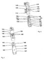
- the part partially represented on the Figures 1 to 7 advantageously comprises locking means 31 of the activation means 7 in the activated position.
- These locking means 31 may for example take the form of two projections 32 respectively disposed on the two inner faces of the two flexible branches 10, respectively able to penetrate into two complementary housing 33 formed on the movable member 21, for example on the corner 23, under the effect of an elastic return of the flexible branches, when the movable element 21 is in the active position, that is to say in place inside the V, the branches 10 of the latter then being sufficiently spaced for that the stop faces 16 are vis-à-vis the ends of the tulip, as shown on the figure 4 .
- the part partially represented on the Figures 1 to 7 comprises advantageously means for unlocking the activation means 7, to allow the passage of the latter from the locked active position to the rest position.
- These unlocking means comprise a suitable shape of the projections 32 and complementary housing 33 constituting the locking means 31 so that, when the projections 32 are in the recesses 33, respectively, they can emerge by pulling the movable element 21 in the opposite direction to that which allowed the locking of this movable element 21 in the abutment 3.
- the appropriate form of the projections will for example be a prismatic shape extending over the width of a flexible arm 10, the cross section is for example triangular and having a stop face parallel to an opposite complementary face of the housing 33, having an inclination angle for example between 30 ° and 60 ° relative to the longitudinal axis of the V branches of the stop 3.
- the unlocking means furthermore advantageously comprise an opening 34 made in the movable element 21 in the lower part thereof, as shown in FIGS. Figures 1 to 7 , in order to allow the passage of a suitable hook-type tool in the opening 34, to exert a pull down and thus unlock the activation means 7 to make the abutment 3 passive (rest position).
- This opening can be achieved by crossing the plate 22 of the movable member 21 and the corner 23 as shown.
- the unlocking of the activation means by traction on the movable element 21, can be performed regardless of the position of the shutter in the opening of the building or the like, and in particular according to the most appropriate position for the operator.
- the opening 34 will preferably be performed in an area of the movable member 21 closest to the bearing face 27, in order to be easily accessible to the operator. It should be noted that this opening 34 may be placed near the lower edge of the final blade, and therefore will be much more accessible than the branches of the V-stop themselves.
- At least one additional projection similar to a projection 32 described above, associated respectively with at least one housing (not shown) additional like a housing 33 described above, can be formed respectively on the face of the plate 22, opposite the fixing face of the wedge 23, and on the plate 13 of the abutment 3 opposite the plate 22.
- This additional projection and housing may strengthen the locking means 31 described above, by constituting an additional locking means of the movable member 21 on the stop 3 in a plane transverse to the plane of the deck 6.
- This additional locking means can intervene in the two active and passive positions of the movable element 21, for example by producing a projection on the plate 13 and two corresponding housings on the plate 22, one for each position distinct from the movable element .
- the part partially represented on the Figures 1 to 7 advantageously comprises connecting means 35 of the activation means 7, to the stop 3, in the rest position, so that the activation means 7 remain integral with it regardless of the position adopted, rest or active .
- the locking means 31 rigidly and removably connect the activation means 7 to the stop 3 in the active position.
- connection means 35 of the activation means 7, to the abutment 3, in the rest position advantageously comprise two lugs 36 attached to the plate 22 of the movable element 21 and extending perpendicularly thereto towards the branches flexible 10, so as to respectively bear on the stop faces 16 of each flexible branch 10 when the movable member 21 is in the rest position, as shown in the figures 5 , 1 , and 2 , thus preventing a complete dissociation of the activation means 7 of the abutment 3.
- the two lugs 36 may advantageously serve, for a part of the displacement at least, for guiding the movable element 21 on the two flexible branches 10, the latter being trapped between the corner 23 on their inner faces, and respectively the two lugs 36 on their outer faces, as shown in FIG. figure 6 .
- the two lugs 36 can be away from the branches, as shown on the figure 4 .
- the two lugs 36 may advantageously take the form of two bumpers perpendicular to the plate 22 and each having a bearing surface 40, for example flat or other surface suitable for this function, vis-à-vis the two outer surfaces of the two branches flexible 10 respectively.
- This bearing surface 40 also serves to ensure the return of the flexible branches 10 in the rest position when the movable member 21 moves from the active position to the rest position, that is to say ensure the approximation of flexible branches 10 towards each other.
- the lugs 36 guarantee the return of the flexible branches 10 in the rest position by forcing them to approach each other during the movement of the movable element 21 towards the rest position.
- the two lugs 36 are preferably placed in the tapered zone of the end 41 of the wedge 23 and on either side thereof, as shown in FIGS.
- the distance separating the two lugs 36 is fixed, in a direction perpendicular to the surface of the deck 6, and it is found that when the wedge 23 passes from the rest position to the active position, the end of the branches 10 is spacing apart from one another under the effect of the wedge 23, but the lugs 36 are simultaneously approaching the root of the flexible branches 10, so that the distance separating the flexible branches 10 remains substantially constant during the movement of the movable element 21 at the two lugs 36: and the fixed spacing of the two lugs 36 does not interfere or oppose, the variable spacing of the flexible legs 10 during the transition from the rest position to the position active stopper 3.
- the lugs 36 via their support surfaces 40 at least partially supported during the transition from a rest state to an active state of the stop 3 or vice versa, participate in the guide means 28 in translation of the activation means 7 in a direction parallel to the lateral guide rails 1.
- the Figures 1 to 4 show that the distance separating the two outer surfaces of the flexible branches 10 is substantially the same at the end of the branches where the bearing faces 16 are and in the rest position on the one hand, and at the root of the flexible branches 10 and in the active position on the other hand. It can be assumed as explained above that this distance is slightly lower in the second situation with respect to the first, so that the lugs 36 no longer touch the flexible branches 10 in the active position.
- the connecting means of the activation means to the stop are constituted by the pins 136 housed and guided in the slots 150 and 151 which constitute a limit of the displacement of the movable element 121 towards the position of rest when the upper end of the lights abuts against the pins 136 formed on the flexible branches in the rest position.
- the lights 150 and 151 assist the wedge for the spacing of the flexible branches 110, the wedge 123 giving the stop 103 its resistance in the active position.
- the abutment 3 or 103 and the activation means 7 or 107 may be made of rigid plastic material having elastic properties for the flexible branches 10 or 110, and obtained by molding.
- the stop 3, 103 the plate 13, 113 and the embedding means 14, 114 are advantageously made integrally in a first piece, and the activation means comprising the plate 22, 122 and the wedge 23, 123 may advantageously be made in one piece in a single piece, linked to the first by a link having at least one degree of freedom in translation as explained above.
- the abutment assembly 3, 103 and activation means 7, 107 is a push-fit end piece of rolling shutter deck blade, as described above.
- the apron can then be unwound in the opening of the building or the like, by crossing the tulips, and the arrival of the deck at the bottom of the opening will automatically place the activation means in the active position as explained above; when the apron is raised the active stops come to limit the winding of the apron in the trunk.
- the active positioning of the activation means of the stop can be performed manually by an operator before the arrival at the end of travel of the apron at the bottom of the opening.
Landscapes
- Engineering & Computer Science (AREA)
- Structural Engineering (AREA)
- Architecture (AREA)
- Civil Engineering (AREA)
- Operating, Guiding And Securing Of Roll- Type Closing Members (AREA)
Claims (11)
- Rollladen (5) zum Anbringen in einer Öffnung eines Gebäudes oder dergleichen, wobei der Rollladen aufweist:- einen Rollladenpanzer (6) mit gliedartig verbundenen Lamellen, die geeignet sind, sich in der Öffnung abzurollen und sich in einem an der Öffnung angrenzenden Kasten aufzurollen,- zwei Führungsschienen (1) seitlich des Rollladenpanzers, die jeweils zum Befestigen an den zwei vertikalen gegenüberliegenden Beschlägen der Öffnung bestimmt sind,- zwei Einlauftrichter (2) zum Führen des Eintritts des Rollladenpanzers jeweils in die Führungsschienen,- mindestens einen Begrenzer (3, 103) zum Begrenzen des Abrollens des Rolladenpanzers in dem Kasten, der an einem Ende einer Lamelle des Rollladenpanzers angeordnet ist und geeignet ist, den Durchtritt durch mindestens einen der zwei Einlauftrichter in Abrollrichtung des Rollladenpanzers zu ermöglichen und den Durchtritt durch den mindestens einen Einlauftrichter in Aufrollrichtung des Rollladenpanzers zu verhindern,- Betätigungsmittel (7, 107) des mindestens einen Begrenzers, die mit dem Letzteren so zusammenwirken, dass sie geeignet sind, die zwei folgenden verschiedenen Positionen anzunehmen:- eine erste Position, wenn die Betätigungsmittel in Ruhe sind, bezeichnet als Ruhestellung, die einen freien Durchtritt des Begrenzers durch den mindestens einen Einlauftrichter zulässt,- eine zweite Position, wenn die Betätigungsmittel betätigt sind, bezeichnet als Wirkstellung, die einen Durchtritt des Begrenzers durch den mindestens einen Einlauftrichter verhindert,
dadurch gekennzeichnet,- dass der mindestens eine Begrenzer (3, 103) zwei flexible Schenkel (10, 110) aufweist, zwischen denen die Betätigungsmittel (7, 107) verschiebbar angeordnet sind, wobei gemäß zumindest einer Ruheposition eine Annäherung der flexiblen Schenkel (10, 110) zueinander entsprechend der Ruheposition des Begrenzers (3, 103) erlaubt ist und eine Wirkposition ein Auseinanderspreizen der flexiblen Schenkel (10, 110) durch eine Verformung zumindest einer der zwei flexiblen Schenkel (10, 110) entsprechend der Wirkposition des Begrenzers (3, 103) erlaubt. - Rollladen nach Anspruch 1'
dadurch gekennzeichnet,
dass er Mittel (28, 128) zum Führen der Betätigungsmittel (7, 107) bei Verschiebung entlang einer zu den seitlichen Führungsschienen (1) parallelen Richtung (11) aufweist. - Rollladen nach Anspruch 1 oder 2
dadurch gekennzeichnet,
dass die zwei flexiblen Schenkel (10, 110) des Begrenzers (3, 103) eine V-Form bilden, deren Längsachse (11) parallel zu den Führungsschienen (1) ist und bei der die Öffnung (12, 112) der flexiblen Schenkel dem Unterteil (4) der Öffnung in einem Gebäude oder dergleichen zugewandt ist. - Rollladen nach einem der Ansprüche 1 bis 3
dadurch gekennzeichnet,
dass die Betätigungsmittel (7, 107) ein bewegliches Element (21, 121) aufweisen, dass geeignet ist, mit dem Unterteil (4) der Öffnung in einem Gebäude oder dergleichen in Kontakt zu kommen, wobei das bewegliche Element geeignet ist, von der Ruheposition in die Wirkposition überzugehen, wenn der Rollladenpanzer (6) mit gliedartig verbundenen Lamellen in Auflage mit dem Unterteil der Öffnung in einem Gebäude oder dergleichen kommt. - Rollladen nach Anspruche 3 oder 4
dadurch gekennzeichnet,- dass, wenn die Betätigungsmittel (7, 107) in Ruhe sind, das bewegliche Element (21, 121) zwischen den flexiblen Schenkeln (10, 110) des zumindest einen Begrenzers (3, 103) so am Eingang des V angeordnet ist, dass diese flexiblen Schenkel (10, 110) zueinander entlang einer Querrichtung senkrecht zur Längsachse (11) der Führungsschienen (1) angenähert sind, um den zumindest einen Begrenzer (3, 103) in Ruheposition zu positionieren, damit der Durchtritt durch den zumindest einen Einlauftrichter (2) in den zwei Bewegungsrichtungen des Rollladenpanzers (6) (Aufrollen und Abrollen) möglich ist, und- dass, wenn die Betätigungsmittel (7, 107) betätigt werden, das bewegliche Element (21, 121) zwischen den flexiblen Schenkeln (10, 110) des zumindest einen Begrenzers (3, 103) so in Richtung zum Boden des V angeordnet ist, dass diese flexiblen Schenkel voneinander entlang einer Querrichtung senkrecht zur Längsachse (11) der Führungsschienen (1) gespreizt werden, um den zumindest einen Begrenzer (3, 103) zum Begrenzen des Aufrollens des Rollladenpanzers (6) im Kasten zu betätigen, indem der Durchtritt durch den zumindest einen Einlauftrichter (2) in Aufrollrichtung verhindert wird. - Rollladen nach einem der Ansprüche 1 bis 5
dadurch gekennzeichnet,
dass er Mittel (31) zum Verriegeln der Betätigungsmittel (7, 107) in aktivierter Position aufweist. - Rollladen nach Anspruch 6
dadurch gekennzeichnet,
dass er Mittel (34, 134) zum Entriegeln der Betätigungsmittel (7, 107) aufweist, um den Übergang dieser Letzteren von der Wirkposition in die Ruheposition zu ermöglichen. - Rollladen nach einem der Ansprüche 1 bis 7
dadurch gekennzeichnet,
dass er Mittel (40, 140) zum Bewegen der zwei flexiblen Schenkel (10, 110) des Begrenzers (3, 103) aufweist, um sie einander anzunähern, wenn die Betätigungsmittel (7, 107) von der Wirkposition in die Ruheposition übergehen. - Rollladen nach einem der Ansprüche 1 bis 8
dadurch gekennzeichnet,
dass er Mittel (35) zum Verbinden der Betätigungsmittel (7, 107) mit dem Begrenzer (3, 103) in Ruheposition aufweist, so dass die Betätigungsmittel unabhängig davon, ob die Ruhe- oder Wirkposition eingenommen wird, mit diesen verbunden bleiben. - Rollladen nach einem der Ansprüche 8 und 9
dadurch gekennzeichnet,
dass die Mittel (40, 140) zum Bewegen und die Mittel (35) zum Verbinden kombiniert sind und die Form von zwei Zentrierzapfen (36) oder von Formstücken (136) aufweisen, die jeweils mit den Betätigungsmitteln (7) oder den flexiblen Schenkeln (110) verbunden sind. - Rollladen nach einem der Ansprüche 1 bis 10
dadurch gekennzeichnet,
dass er Mittel (14, 114) zum Einbau des Begrenzers (3) und der damit verbundenen Betätigungsmittel (7, 107) in einem seitlichen Ende (9) einer Lamelle des Rollladenpanzers (6) aufweist, um eine Lamellenabdeckung zu bilden.
Applications Claiming Priority (1)
| Application Number | Priority Date | Filing Date | Title |
|---|---|---|---|
| FR0704955A FR2918699A1 (fr) | 2007-07-09 | 2007-07-09 | Volet roulant comportant un dispositif de butee pour limiter l'enroulement du tablier dans le coffre. |
Publications (2)
| Publication Number | Publication Date |
|---|---|
| EP2014864A1 EP2014864A1 (de) | 2009-01-14 |
| EP2014864B1 true EP2014864B1 (de) | 2010-10-20 |
Family
ID=38996647
Family Applications (1)
| Application Number | Title | Priority Date | Filing Date |
|---|---|---|---|
| EP08352014A Active EP2014864B1 (de) | 2007-07-09 | 2008-07-03 | Rollladen mit einer Anschlagvorrichtung zur Begrenzung der Aufrollung des Rollladenpanzers in den Rollladenkasten |
Country Status (4)
| Country | Link |
|---|---|
| EP (1) | EP2014864B1 (de) |
| AT (1) | ATE485437T1 (de) |
| DE (1) | DE602008003064D1 (de) |
| FR (1) | FR2918699A1 (de) |
Families Citing this family (5)
| Publication number | Priority date | Publication date | Assignee | Title |
|---|---|---|---|---|
| FR2975725B1 (fr) * | 2011-05-26 | 2013-06-21 | Bubendorff | Dispositif de limitation du repliement du tablier d'un systeme d'occultation, tablier comportant un tel dispositif de limitation et systeme d'occultation comportant un tel tablier |
| JP6324095B2 (ja) * | 2014-02-04 | 2018-05-16 | 文化シヤッター株式会社 | 開閉装置の開閉体停止装置 |
| DE102018107546A1 (de) | 2018-03-29 | 2019-10-02 | Warema Renkhoff Se | Sonnenschutz- oder Rollladenanlage mit Anschlägen in Führungsschienen für ein Schienenelement |
| IL263745A (en) * | 2018-12-16 | 2020-06-30 | Yedidia Hagay | A lock for locking the curtain of a roller shutter |
| FR3122447A1 (fr) | 2021-05-03 | 2022-11-04 | Moulages Plastiques Du Midi | Butée pour volet roulant ou similaire |
Family Cites Families (6)
| Publication number | Priority date | Publication date | Assignee | Title |
|---|---|---|---|---|
| DE1266476B (de) * | 1963-11-19 | 1968-04-18 | Philipp Sauer | Anschlagwinkel fuer Fenster-Rollaeden |
| DE3214092A1 (de) * | 1982-04-16 | 1983-10-20 | Alukon F. Grashei Kg, 8671 Konradsreuth | Vorrichtung zur begrenzung der aufwickelbewegung eines rolladenpanzers oder dergleichen |
| DE29611369U1 (de) | 1996-06-29 | 1996-09-05 | Beckhoff Alulux Gmbh & Co | In seitlichen Führungsschienen geführter Rolladen |
| AT411088B (de) * | 2001-12-13 | 2003-09-25 | Schlotterer Rollladen Systeme | Stab für verschiebbare, öffnungen zugeordnete vorrichtungen, wie rollläden |
| DE10304899B4 (de) * | 2003-02-06 | 2004-12-09 | Roma Rolladensysteme Gmbh | Rollladen |
| FR2893347B1 (fr) * | 2005-11-17 | 2008-01-04 | Eveno Sas Soc Par Actions Simp | Volet roulant muni d'un dispositif de butee haute |
-
2007
- 2007-07-09 FR FR0704955A patent/FR2918699A1/fr active Pending
-
2008
- 2008-07-03 AT AT08352014T patent/ATE485437T1/de not_active IP Right Cessation
- 2008-07-03 EP EP08352014A patent/EP2014864B1/de active Active
- 2008-07-03 DE DE602008003064T patent/DE602008003064D1/de active Active
Also Published As
| Publication number | Publication date |
|---|---|
| EP2014864A1 (de) | 2009-01-14 |
| ATE485437T1 (de) | 2010-11-15 |
| FR2918699A1 (fr) | 2009-01-16 |
| DE602008003064D1 (de) | 2010-12-02 |
Similar Documents
| Publication | Publication Date | Title |
|---|---|---|
| EP1839713B1 (de) | Einheit aus einem Langlaufski und einer Langlaufbindung | |
| EP2014864B1 (de) | Rollladen mit einer Anschlagvorrichtung zur Begrenzung der Aufrollung des Rollladenpanzers in den Rollladenkasten | |
| EP0422382B1 (de) | Einrichtung beim Langlaufski um Rückwärtsgleiten zu vermeiden | |
| FR2788001A1 (fr) | Table de tennis de table pliable equipee de moyens de verrouillage | |
| EP0055166B1 (de) | Mechanische Triebketten- oder Riemenspanneinrichtung | |
| FR3051506A1 (fr) | Installation de volet roulant comprenant un dispositif de blocage du tablier | |
| WO2012143519A1 (fr) | Dispositif de suspension d'une toile | |
| EP0922606B1 (de) | Anordnung für einen ausnehmbaren und in Längsrichtung verstellbaren Sitz im Innenraum eines Kraftfahrzeuges | |
| FR2629996A1 (fr) | Ecran adaptable a une baignoire, integrant un dispositif de coulissement vertical des parois | |
| FR3075847A1 (fr) | Verrou et trappe comprenant un tel verrou | |
| FR2918101A1 (fr) | Verrou de securite automatique pour volet roulant, et volet roulant equipe d'un tel verrou. | |
| EP1026363B1 (de) | Sicherheitsvorrichtung gegen das Hochschieben von Rolläden | |
| FR2749880A1 (fr) | Embout de lames de volet roulant et volet roulant equipe de tels embouts | |
| FR2919335A1 (fr) | Dispositif de liaison entre un arbre rotatif et un tablier a lames articulees de volet roulant assurant notamment une fonction anti-relevage de securite. | |
| EP2672039B1 (de) | Hubvorrichtung für Element eines Schutzdachs für Becken | |
| FR2962759A1 (fr) | Volet roulant inclinable automatique | |
| FR2538258A1 (fr) | Frein de ski | |
| FR2955136A1 (fr) | Arret de vantail | |
| FR3022514A1 (fr) | Ensemble d’essuyage d’une vitre de vehicule automobile comportant une tete de montage et un bras d’entrainement | |
| EP1034813B1 (de) | Sicherheitsreling | |
| FR2757694A1 (fr) | Dispositif de verrouillage pour la mise en place d'une perche de distribution electrique, et perche de distribution ainsi verrouillee | |
| WO1990000870A1 (fr) | Perfectionnement a une installation et procede d'entrainement de chariots sur rails, notamment pour le rangement et la mise en place de rangees de sieges | |
| EP4444617A1 (de) | Trennwand für eine flugzeugsitzanordnung mit schiebetür und zugehörige flugzeugsitzanordnung | |
| FR2746433A1 (fr) | Tribune telescopique munie d'un dispositif de blocage entre rangs | |
| WO1989006300A1 (fr) | Systeme d'entrainement de chariots sur un rail et procede pour sa mise en oeuvre |
Legal Events
| Date | Code | Title | Description |
|---|---|---|---|
| PUAI | Public reference made under article 153(3) epc to a published international application that has entered the european phase |
Free format text: ORIGINAL CODE: 0009012 |
|
| AK | Designated contracting states |
Kind code of ref document: A1 Designated state(s): AT BE BG CH CY CZ DE DK EE ES FI FR GB GR HR HU IE IS IT LI LT LU LV MC MT NL NO PL PT RO SE SI SK TR |
|
| AX | Request for extension of the european patent |
Extension state: AL BA MK RS |
|
| 17P | Request for examination filed |
Effective date: 20090702 |
|
| AKX | Designation fees paid |
Designated state(s): AT BE BG CH CY CZ DE DK EE ES FI FR GB GR HR HU IE IS IT LI LT LU LV MC MT NL NO PL PT RO SE SI SK TR |
|
| GRAP | Despatch of communication of intention to grant a patent |
Free format text: ORIGINAL CODE: EPIDOSNIGR1 |
|
| GRAS | Grant fee paid |
Free format text: ORIGINAL CODE: EPIDOSNIGR3 |
|
| GRAA | (expected) grant |
Free format text: ORIGINAL CODE: 0009210 |
|
| AK | Designated contracting states |
Kind code of ref document: B1 Designated state(s): AT BE BG CH CY CZ DE DK EE ES FI FR GB GR HR HU IE IS IT LI LT LU LV MC MT NL NO PL PT RO SE SI SK TR |
|
| REG | Reference to a national code |
Ref country code: GB Ref legal event code: FG4D Free format text: NOT ENGLISH |
|
| REG | Reference to a national code |
Ref country code: CH Ref legal event code: EP |
|
| REG | Reference to a national code |
Ref country code: IE Ref legal event code: FG4D Free format text: LANGUAGE OF EP DOCUMENT: FRENCH |
|
| REF | Corresponds to: |
Ref document number: 602008003064 Country of ref document: DE Date of ref document: 20101202 Kind code of ref document: P |
|
| REG | Reference to a national code |
Ref country code: NL Ref legal event code: VDEP Effective date: 20101020 |
|
| LTIE | Lt: invalidation of european patent or patent extension |
Effective date: 20101020 |
|
| PG25 | Lapsed in a contracting state [announced via postgrant information from national office to epo] |
Ref country code: LT Free format text: LAPSE BECAUSE OF FAILURE TO SUBMIT A TRANSLATION OF THE DESCRIPTION OR TO PAY THE FEE WITHIN THE PRESCRIBED TIME-LIMIT Effective date: 20101020 Ref country code: NO Free format text: LAPSE BECAUSE OF FAILURE TO SUBMIT A TRANSLATION OF THE DESCRIPTION OR TO PAY THE FEE WITHIN THE PRESCRIBED TIME-LIMIT Effective date: 20110120 |
|
| REG | Reference to a national code |
Ref country code: IE Ref legal event code: FD4D |
|
| PG25 | Lapsed in a contracting state [announced via postgrant information from national office to epo] |
Ref country code: SI Free format text: LAPSE BECAUSE OF FAILURE TO SUBMIT A TRANSLATION OF THE DESCRIPTION OR TO PAY THE FEE WITHIN THE PRESCRIBED TIME-LIMIT Effective date: 20101020 Ref country code: BG Free format text: LAPSE BECAUSE OF FAILURE TO SUBMIT A TRANSLATION OF THE DESCRIPTION OR TO PAY THE FEE WITHIN THE PRESCRIBED TIME-LIMIT Effective date: 20110120 Ref country code: AT Free format text: LAPSE BECAUSE OF FAILURE TO SUBMIT A TRANSLATION OF THE DESCRIPTION OR TO PAY THE FEE WITHIN THE PRESCRIBED TIME-LIMIT Effective date: 20101020 Ref country code: HR Free format text: LAPSE BECAUSE OF FAILURE TO SUBMIT A TRANSLATION OF THE DESCRIPTION OR TO PAY THE FEE WITHIN THE PRESCRIBED TIME-LIMIT Effective date: 20101020 Ref country code: NL Free format text: LAPSE BECAUSE OF FAILURE TO SUBMIT A TRANSLATION OF THE DESCRIPTION OR TO PAY THE FEE WITHIN THE PRESCRIBED TIME-LIMIT Effective date: 20101020 Ref country code: LV Free format text: LAPSE BECAUSE OF FAILURE TO SUBMIT A TRANSLATION OF THE DESCRIPTION OR TO PAY THE FEE WITHIN THE PRESCRIBED TIME-LIMIT Effective date: 20101020 Ref country code: PT Free format text: LAPSE BECAUSE OF FAILURE TO SUBMIT A TRANSLATION OF THE DESCRIPTION OR TO PAY THE FEE WITHIN THE PRESCRIBED TIME-LIMIT Effective date: 20110221 Ref country code: FI Free format text: LAPSE BECAUSE OF FAILURE TO SUBMIT A TRANSLATION OF THE DESCRIPTION OR TO PAY THE FEE WITHIN THE PRESCRIBED TIME-LIMIT Effective date: 20101020 Ref country code: IS Free format text: LAPSE BECAUSE OF FAILURE TO SUBMIT A TRANSLATION OF THE DESCRIPTION OR TO PAY THE FEE WITHIN THE PRESCRIBED TIME-LIMIT Effective date: 20110220 Ref country code: SE Free format text: LAPSE BECAUSE OF FAILURE TO SUBMIT A TRANSLATION OF THE DESCRIPTION OR TO PAY THE FEE WITHIN THE PRESCRIBED TIME-LIMIT Effective date: 20101020 |
|
| PG25 | Lapsed in a contracting state [announced via postgrant information from national office to epo] |
Ref country code: GR Free format text: LAPSE BECAUSE OF FAILURE TO SUBMIT A TRANSLATION OF THE DESCRIPTION OR TO PAY THE FEE WITHIN THE PRESCRIBED TIME-LIMIT Effective date: 20110121 |
|
| PG25 | Lapsed in a contracting state [announced via postgrant information from national office to epo] |
Ref country code: ES Free format text: LAPSE BECAUSE OF FAILURE TO SUBMIT A TRANSLATION OF THE DESCRIPTION OR TO PAY THE FEE WITHIN THE PRESCRIBED TIME-LIMIT Effective date: 20110131 Ref country code: EE Free format text: LAPSE BECAUSE OF FAILURE TO SUBMIT A TRANSLATION OF THE DESCRIPTION OR TO PAY THE FEE WITHIN THE PRESCRIBED TIME-LIMIT Effective date: 20101020 Ref country code: IE Free format text: LAPSE BECAUSE OF FAILURE TO SUBMIT A TRANSLATION OF THE DESCRIPTION OR TO PAY THE FEE WITHIN THE PRESCRIBED TIME-LIMIT Effective date: 20101020 Ref country code: CZ Free format text: LAPSE BECAUSE OF FAILURE TO SUBMIT A TRANSLATION OF THE DESCRIPTION OR TO PAY THE FEE WITHIN THE PRESCRIBED TIME-LIMIT Effective date: 20101020 |
|
| PLBE | No opposition filed within time limit |
Free format text: ORIGINAL CODE: 0009261 |
|
| STAA | Information on the status of an ep patent application or granted ep patent |
Free format text: STATUS: NO OPPOSITION FILED WITHIN TIME LIMIT |
|
| PG25 | Lapsed in a contracting state [announced via postgrant information from national office to epo] |
Ref country code: RO Free format text: LAPSE BECAUSE OF FAILURE TO SUBMIT A TRANSLATION OF THE DESCRIPTION OR TO PAY THE FEE WITHIN THE PRESCRIBED TIME-LIMIT Effective date: 20101020 Ref country code: DK Free format text: LAPSE BECAUSE OF FAILURE TO SUBMIT A TRANSLATION OF THE DESCRIPTION OR TO PAY THE FEE WITHIN THE PRESCRIBED TIME-LIMIT Effective date: 20101020 Ref country code: PL Free format text: LAPSE BECAUSE OF FAILURE TO SUBMIT A TRANSLATION OF THE DESCRIPTION OR TO PAY THE FEE WITHIN THE PRESCRIBED TIME-LIMIT Effective date: 20101020 Ref country code: SK Free format text: LAPSE BECAUSE OF FAILURE TO SUBMIT A TRANSLATION OF THE DESCRIPTION OR TO PAY THE FEE WITHIN THE PRESCRIBED TIME-LIMIT Effective date: 20101020 |
|
| 26N | No opposition filed |
Effective date: 20110721 |
|
| REG | Reference to a national code |
Ref country code: DE Ref legal event code: R097 Ref document number: 602008003064 Country of ref document: DE Effective date: 20110721 |
|
| PG25 | Lapsed in a contracting state [announced via postgrant information from national office to epo] |
Ref country code: MT Free format text: LAPSE BECAUSE OF FAILURE TO SUBMIT A TRANSLATION OF THE DESCRIPTION OR TO PAY THE FEE WITHIN THE PRESCRIBED TIME-LIMIT Effective date: 20101020 Ref country code: IT Free format text: LAPSE BECAUSE OF FAILURE TO SUBMIT A TRANSLATION OF THE DESCRIPTION OR TO PAY THE FEE WITHIN THE PRESCRIBED TIME-LIMIT Effective date: 20101020 |
|
| PG25 | Lapsed in a contracting state [announced via postgrant information from national office to epo] |
Ref country code: MC Free format text: LAPSE BECAUSE OF NON-PAYMENT OF DUE FEES Effective date: 20110731 |
|
| REG | Reference to a national code |
Ref country code: CH Ref legal event code: PL |
|
| GBPC | Gb: european patent ceased through non-payment of renewal fee |
Effective date: 20120703 |
|
| PG25 | Lapsed in a contracting state [announced via postgrant information from national office to epo] |
Ref country code: CH Free format text: LAPSE BECAUSE OF NON-PAYMENT OF DUE FEES Effective date: 20120731 Ref country code: LI Free format text: LAPSE BECAUSE OF NON-PAYMENT OF DUE FEES Effective date: 20120731 Ref country code: GB Free format text: LAPSE BECAUSE OF NON-PAYMENT OF DUE FEES Effective date: 20120703 |
|
| PG25 | Lapsed in a contracting state [announced via postgrant information from national office to epo] |
Ref country code: LU Free format text: LAPSE BECAUSE OF NON-PAYMENT OF DUE FEES Effective date: 20110703 Ref country code: CY Free format text: LAPSE BECAUSE OF EXPIRATION OF PROTECTION Effective date: 20101020 |
|
| PG25 | Lapsed in a contracting state [announced via postgrant information from national office to epo] |
Ref country code: TR Free format text: LAPSE BECAUSE OF FAILURE TO SUBMIT A TRANSLATION OF THE DESCRIPTION OR TO PAY THE FEE WITHIN THE PRESCRIBED TIME-LIMIT Effective date: 20101020 |
|
| PG25 | Lapsed in a contracting state [announced via postgrant information from national office to epo] |
Ref country code: HU Free format text: LAPSE BECAUSE OF FAILURE TO SUBMIT A TRANSLATION OF THE DESCRIPTION OR TO PAY THE FEE WITHIN THE PRESCRIBED TIME-LIMIT Effective date: 20101020 |
|
| REG | Reference to a national code |
Ref country code: FR Ref legal event code: PLFP Year of fee payment: 9 |
|
| REG | Reference to a national code |
Ref country code: FR Ref legal event code: PLFP Year of fee payment: 10 |
|
| REG | Reference to a national code |
Ref country code: FR Ref legal event code: PLFP Year of fee payment: 11 |
|
| REG | Reference to a national code |
Ref country code: DE Ref legal event code: R082 Ref document number: 602008003064 Country of ref document: DE Representative=s name: WUNDERLICH & HEIM PATENTANWAELTE PARTNERSCHAFT, DE |
|
| PGFP | Annual fee paid to national office [announced via postgrant information from national office to epo] |
Ref country code: FR Payment date: 20250617 Year of fee payment: 18 |
|
| PGFP | Annual fee paid to national office [announced via postgrant information from national office to epo] |
Ref country code: DE Payment date: 20250711 Year of fee payment: 18 |
|
| PGFP | Annual fee paid to national office [announced via postgrant information from national office to epo] |
Ref country code: BE Payment date: 20250724 Year of fee payment: 18 |