EP2014869A1 - Equilibrage de rotor aubé - Google Patents
Equilibrage de rotor aubé Download PDFInfo
- Publication number
- EP2014869A1 EP2014869A1 EP08011076A EP08011076A EP2014869A1 EP 2014869 A1 EP2014869 A1 EP 2014869A1 EP 08011076 A EP08011076 A EP 08011076A EP 08011076 A EP08011076 A EP 08011076A EP 2014869 A1 EP2014869 A1 EP 2014869A1
- Authority
- EP
- European Patent Office
- Prior art keywords
- cavity
- mass
- centre
- rotor
- phase
- Prior art date
- Legal status (The legal status is an assumption and is not a legal conclusion. Google has not performed a legal analysis and makes no representation as to the accuracy of the status listed.)
- Granted
Links
- 239000000463 material Substances 0.000 claims abstract description 70
- 238000004519 manufacturing process Methods 0.000 claims abstract description 23
- 238000000034 method Methods 0.000 claims abstract description 16
- 238000013016 damping Methods 0.000 claims description 15
- 239000006260 foam Substances 0.000 claims 2
- 239000000945 filler Substances 0.000 description 39
- 230000000712 assembly Effects 0.000 description 5
- 238000000429 assembly Methods 0.000 description 5
- 238000009826 distribution Methods 0.000 description 5
- 230000000694 effects Effects 0.000 description 5
- 239000002184 metal Substances 0.000 description 3
- 230000010355 oscillation Effects 0.000 description 2
- QXJJQWWVWRCVQT-UHFFFAOYSA-K calcium;sodium;phosphate Chemical compound [Na+].[Ca+2].[O-]P([O-])([O-])=O QXJJQWWVWRCVQT-UHFFFAOYSA-K 0.000 description 1
- 239000011248 coating agent Substances 0.000 description 1
- 238000000576 coating method Methods 0.000 description 1
- 238000012217 deletion Methods 0.000 description 1
- 230000037430 deletion Effects 0.000 description 1
- 238000006073 displacement reaction Methods 0.000 description 1
- 238000005555 metalworking Methods 0.000 description 1
- 238000009419 refurbishment Methods 0.000 description 1
- 230000000717 retained effect Effects 0.000 description 1
- 238000007789 sealing Methods 0.000 description 1
- 239000003190 viscoelastic substance Substances 0.000 description 1
Images


Classifications
-
- F—MECHANICAL ENGINEERING; LIGHTING; HEATING; WEAPONS; BLASTING
- F04—POSITIVE - DISPLACEMENT MACHINES FOR LIQUIDS; PUMPS FOR LIQUIDS OR ELASTIC FLUIDS
- F04D—NON-POSITIVE-DISPLACEMENT PUMPS
- F04D29/00—Details, component parts, or accessories
- F04D29/26—Rotors specially for elastic fluids
- F04D29/32—Rotors specially for elastic fluids for axial flow pumps
- F04D29/321—Rotors specially for elastic fluids for axial flow pumps for axial flow compressors
- F04D29/324—Blades
-
- F—MECHANICAL ENGINEERING; LIGHTING; HEATING; WEAPONS; BLASTING
- F01—MACHINES OR ENGINES IN GENERAL; ENGINE PLANTS IN GENERAL; STEAM ENGINES
- F01D—NON-POSITIVE DISPLACEMENT MACHINES OR ENGINES, e.g. STEAM TURBINES
- F01D5/00—Blades; Blade-carrying members; Heating, heat-insulating, cooling or antivibration means on the blades or the members
- F01D5/02—Blade-carrying members, e.g. rotors
- F01D5/027—Arrangements for balancing
-
- F—MECHANICAL ENGINEERING; LIGHTING; HEATING; WEAPONS; BLASTING
- F01—MACHINES OR ENGINES IN GENERAL; ENGINE PLANTS IN GENERAL; STEAM ENGINES
- F01D—NON-POSITIVE DISPLACEMENT MACHINES OR ENGINES, e.g. STEAM TURBINES
- F01D5/00—Blades; Blade-carrying members; Heating, heat-insulating, cooling or antivibration means on the blades or the members
- F01D5/12—Blades
- F01D5/14—Form or construction
- F01D5/18—Hollow blades, i.e. blades with cooling or heating channels or cavities; Heating, heat-insulating or cooling means on blades
-
- F—MECHANICAL ENGINEERING; LIGHTING; HEATING; WEAPONS; BLASTING
- F04—POSITIVE - DISPLACEMENT MACHINES FOR LIQUIDS; PUMPS FOR LIQUIDS OR ELASTIC FLUIDS
- F04D—NON-POSITIVE-DISPLACEMENT PUMPS
- F04D29/00—Details, component parts, or accessories
- F04D29/26—Rotors specially for elastic fluids
- F04D29/32—Rotors specially for elastic fluids for axial flow pumps
- F04D29/38—Blades
- F04D29/388—Blades characterised by construction
-
- F—MECHANICAL ENGINEERING; LIGHTING; HEATING; WEAPONS; BLASTING
- F04—POSITIVE - DISPLACEMENT MACHINES FOR LIQUIDS; PUMPS FOR LIQUIDS OR ELASTIC FLUIDS
- F04D—NON-POSITIVE-DISPLACEMENT PUMPS
- F04D29/00—Details, component parts, or accessories
- F04D29/66—Combating cavitation, whirls, noise, vibration or the like; Balancing
- F04D29/661—Combating cavitation, whirls, noise, vibration or the like; Balancing especially adapted for elastic fluid pumps
- F04D29/662—Balancing of rotors
-
- F—MECHANICAL ENGINEERING; LIGHTING; HEATING; WEAPONS; BLASTING
- F16—ENGINEERING ELEMENTS AND UNITS; GENERAL MEASURES FOR PRODUCING AND MAINTAINING EFFECTIVE FUNCTIONING OF MACHINES OR INSTALLATIONS; THERMAL INSULATION IN GENERAL
- F16F—SPRINGS; SHOCK-ABSORBERS; MEANS FOR DAMPING VIBRATION
- F16F15/00—Suppression of vibrations in systems; Means or arrangements for avoiding or reducing out-of-balance forces, e.g. due to motion
- F16F15/32—Correcting- or balancing-weights or equivalent means for balancing rotating bodies, e.g. vehicle wheels
-
- Y—GENERAL TAGGING OF NEW TECHNOLOGICAL DEVELOPMENTS; GENERAL TAGGING OF CROSS-SECTIONAL TECHNOLOGIES SPANNING OVER SEVERAL SECTIONS OF THE IPC; TECHNICAL SUBJECTS COVERED BY FORMER USPC CROSS-REFERENCE ART COLLECTIONS [XRACs] AND DIGESTS
- Y02—TECHNOLOGIES OR APPLICATIONS FOR MITIGATION OR ADAPTATION AGAINST CLIMATE CHANGE
- Y02T—CLIMATE CHANGE MITIGATION TECHNOLOGIES RELATED TO TRANSPORTATION
- Y02T50/00—Aeronautics or air transport
- Y02T50/60—Efficient propulsion technologies, e.g. for aircraft
-
- Y—GENERAL TAGGING OF NEW TECHNOLOGICAL DEVELOPMENTS; GENERAL TAGGING OF CROSS-SECTIONAL TECHNOLOGIES SPANNING OVER SEVERAL SECTIONS OF THE IPC; TECHNICAL SUBJECTS COVERED BY FORMER USPC CROSS-REFERENCE ART COLLECTIONS [XRACs] AND DIGESTS
- Y10—TECHNICAL SUBJECTS COVERED BY FORMER USPC
- Y10T—TECHNICAL SUBJECTS COVERED BY FORMER US CLASSIFICATION
- Y10T29/00—Metal working
- Y10T29/49—Method of mechanical manufacture
- Y10T29/49316—Impeller making
-
- Y—GENERAL TAGGING OF NEW TECHNOLOGICAL DEVELOPMENTS; GENERAL TAGGING OF CROSS-SECTIONAL TECHNOLOGIES SPANNING OVER SEVERAL SECTIONS OF THE IPC; TECHNICAL SUBJECTS COVERED BY FORMER USPC CROSS-REFERENCE ART COLLECTIONS [XRACs] AND DIGESTS
- Y10—TECHNICAL SUBJECTS COVERED BY FORMER USPC
- Y10T—TECHNICAL SUBJECTS COVERED BY FORMER US CLASSIFICATION
- Y10T29/00—Metal working
- Y10T29/49—Method of mechanical manufacture
- Y10T29/49316—Impeller making
- Y10T29/4932—Turbomachine making
- Y10T29/49321—Assembling individual fluid flow interacting members, e.g., blades, vanes, buckets, on rotary support member
-
- Y—GENERAL TAGGING OF NEW TECHNOLOGICAL DEVELOPMENTS; GENERAL TAGGING OF CROSS-SECTIONAL TECHNOLOGIES SPANNING OVER SEVERAL SECTIONS OF THE IPC; TECHNICAL SUBJECTS COVERED BY FORMER USPC CROSS-REFERENCE ART COLLECTIONS [XRACs] AND DIGESTS
- Y10—TECHNICAL SUBJECTS COVERED BY FORMER USPC
- Y10T—TECHNICAL SUBJECTS COVERED BY FORMER US CLASSIFICATION
- Y10T29/00—Metal working
- Y10T29/49—Method of mechanical manufacture
- Y10T29/49316—Impeller making
- Y10T29/4932—Turbomachine making
- Y10T29/49325—Shaping integrally bladed rotor
Definitions
- the present invention relates to a method of manufacture of a fan blade assembly and a component made by such a method.
- the invention is particularly, although not exclusively, concerned with components for use in gas turbine engines, for example fan blades.
- High speed rotating assemblies such as fan blade assemblies in gas turbine engines need to be balanced; ie the centre of mass of the assembly needs to be as close as possible to the axis of rotation of the assembly. Any eccentricity resulting from a non-coincident centre of mass and axis of rotation will produce oscillations which may result in elevated vibration levels or resonance (high amplitude oscillation at certain resonant frequencies) potentially damaging the assembly and surrounding components, eg the main engine shaft. Additionally, large deformations may increase blade tip clearance.
- components of fan assemblies include balance correction lands where material can be selectively removed or added late in the manufacturing process to correct any out-of-balance characteristics without affecting the aerodynamics of the blade.
- these lands are necessarily positioned near the blade root (ie away from the aerofoil surface). This is problematic as the hub is positioned at a relatively small radius compared to the blade tip, and as such a significant amount of weight is required in order to give the correct amount of balance. This is because the effect of the added mass in moving the centre of mass of the assembly is proportional to its distance from that centre of mass.
- a relatively small mass imbalance at a first blade tip demands a much larger mass addition to the diametrically opposite fan blade root in order to balance the assembly. This, in turn, adds significant weight to the assembly which as described is undesirable.
- blisk It is also known to provide blades and hubs (or discs) in a single component or blisk. As the blades are non-removably attached to the hub in blisk assemblies, it is not possible to change the balance of the assembly by switching blades (for example exchanging a blade of a first mass moment weight with a blade of a second, different, mass-moment weight). Therefore, blisk designs often include large balance correction lands in order to correct any residual out-of-balance characteristics.
- a method of manufacturing a rotating component comprising the following steps: providing a component comprising a first portion, which first portion defines a first cavity, characterised by; identifying a first inertial property of the first portion and / or the entire component, introducing material into the first cavity to achieve an adjusted inertial property of the first portion and hence a desired inertial property of the component.
- a rotating component comprising: a first portion defining a first cavity, a second portion defining a second cavity, the second portion being circumferentially spaced from said first portion, characterised in that the first cavity has a first material deposit therein, said material having predetermined inertial characteristics so as to adjust the centre of mass of the rotating component.
- the second cavity comprises a second material deposit therein, said second material deposit configured to adjust the centre of mass of the rotating component.
- the configuration of material may vary from blade to blade such that if a damping material is used (for example), the damping function is retained in each blade with the existence of such material whilst the component balance may be altered by providing varying configurations of material from blade to blade.
- the known fan blade assembly 10 comprises a disc, or hub 12 around which are positioned a plurality of circumferentially spaced blades 14.
- Each blade 14 comprises an aerofoil 16 integral with a blade root 18 which connects to the hub 12 in order to retain the blade in position.
- the hub 12 and blades 14 are formed as a single component, known as a blisk.
- the main shaft of a gas turbine engine (not shown) is non-rotationally attached to the hub 12 such that the entire assembly 10 rotates about axis X when the gas turbine engine operates.
- Each of the blades 14 has inertial properties, such as mass, mass distribution and mass-moment-weight which affect the centre of mass of the fan blade assembly. Due to manufacturing tolerances, the blades 14 vary in terms of these inertial properties. As such, the assembly 10 is generally out of balance, with a centre of mass W being spaced apart from an axis of rotation X (when the assembly is rotating in operation).
- a blisk 20 is shown in Figure 2 in accordance with a first embodiment of the present invention.
- Blisk 20 comprises a fan blade body, or aerofoil, 22 and a disk/hub 24.
- the fan blade 22 comprises a cavity 26 suitable for receiving a damping material 28, specifically a hardening visco-elastic material 26 capable of damping vibrations of the blade 22, although any suitable material may be used.
- the filler material 28 is a visco-elastic fill material 29 containing a plurality of hollow glass spheres 30. These hollow spheres 30 do not significantly impact the damping performance of the filler material 28, but rather simply occupy space in the cavity 26 such that less of the visco-elastic component 29 of the filler material 28 can be inserted into cavity 26. Therefore by varying the number of hollow spheres 30 in a given mass of filler material 28, it is possible to alter the density of the filler material (as the visco-elastic component is generally heavier than air).
- first blade with a high density filler material 28 (with a low number of spheres 30) and a second blade which is, by way of example only, circumferentially opposite the first blade, with a low density filler material (ie with a high number of spheres 30).
- filler materials 28 and hollow spheres 30 of different densities could be combined to achieve a desired weight distribution.
- the density of the filler material 28 may be varied by using hollow spheres 30 of different diameter.
- the end result of such processes would be two blades 20 with substantially identical geometry and damping properties, however with significantly different inertial properties (eg mass). This will be discussed further below.
- a predetermined amount of high density filler could be added to the cavity first, followed by a predetermined amount of low density filler.
- the same predetermined amount of low density filler could be added to the cavity first, followed by the same predetermined amount of high density filler. Therefore, the two blades would have the same mass, but different mass distributions (ie the centre of mass of the further blade would be positioned nearer the blade tip).
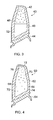
- the blisk 40 is substantially similar to the blisk 20 comprising an aerofoil 42, a disk/hub 44 and a cavity 46.
- the cavity 46 is only partially filled with a visco-elastic filler material 48.
- a remaining part 52 of the cavity 46 remains empty.
- the blisk 40 was inverted with respect of Figure 3 when being filled such that the visco-elastic filler material sits near to the tip of the blisk 40.
- the weight of the blisk 40 may be changed selectively by varying the amount of filler 48 present in the cavity 46. As such, the inertial properties of blisk 40 can be altered in a similar way to blisk 20.
- the damping properties of the filler 48 are most useful near the blade tip as this is the region of highest displacement. It is therefore preferable that the damping material be positioned here. Therefore the vacancy of the portion 52 has little effect on the damping effect of the filler material 48.
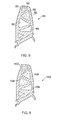
- a blisk 60 is shown made in accordance with a third embodiment of the present invention.
- the blisk 60 is substantially similar to blisk 40 but it will be noted that a cavity 66 has been completely filled with a filler material 68.
- the filler material 68 contains a plurality of compressible hollow spheres 70.
- the filler material 68 is injected into the cavity 66 via an aperture 72.
- it continues to be fed in such that a pressure gradient builds up from the root/base 64 to the tip of the blisk 60.
- the cavity 66 contains filler material 68 ranging from a lower pressure region 74 near the root/base to a high pressure region 76 near the tip. It will be noted that because the spheres 70 are compressible, this high density can be achieved with a substantially incompressible visco-elastic damping material. An increased density of, for example, 20% may be achieved at the high density region 76 over the low density region 74.
- the filler material 68 is of a controllable density, it is possible to vary the inertial properties of the blisk 60 in a similar manner to blisks 20 and 40.
- the high pressure region can be moved by altering the position of the aperture 72.
- a centre-fill, root-fill or combined root and tip fill may be appropriate for creating different locations with one or more high density regions 76.
- Other patterns may be achieved by allowing the filler to set in one region before injecting and pressurising filler in an adjacent region.
- a fan blade 80 made in accordance with a fourth embodiment of the present invention is shown in Figure 5 .
- the fan blade 80 comprises a plurality of cavities 86.
- the cavities 86 may be selectively filled to provide a desired distribution of a filler material 84. Again, this allows for the filler material 84 to be positioned at the tip of the blade where it is most needed, and also for the mass distribution of the filler material 84 to be controlled such that the inertial properties of individual blades 80 can be varied.
- each cavity may also be filled in accordance with any of the previous embodiments 20, 40, 60.
- FIG. 6 Another fan blade 100 is shown in Figure 6 which is substantially similar to blade 80. However, the parts of the blade 100 delimiting the cavities 106 have orifices therethrough such that only a single aperture 102 need be utilised in order to provide filler material 104 into the cavities 106.
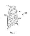
- a further fan blade 130 is shown in Figure 7 which is substantially similar to blade 100.
- the parts of the blade 130 delimiting the cavities 136 have orifices therethrough such that only a single aperture 132 need be utilised in order to provide filler material 134 into the cavities 136.
- a tube 138 is provided between orifices such that cavities 136 can be filled, while cavity 134 is left empty of filler material.
- each of the cavities 26, 46, 66, 86, 106 are substantially completely enclosed within the aerofoil with the exception of orifices with which to fill the cavities. As such the impinging airflow when in use does not contact the filler material, and the surface finish of the blade is intact.
- the fan blade assembly 110 comprises a hub/disk 112 and a plurality of blades 114 manufactured in accordance with the present invention.
- the assembly 110 rotates about axis Y on the engine shaft (not shown).
- the assembly 110 comprises a first fan blade 116 and a second fan blade 118 opposite thereto.
- the assembly 100 Prior to balancing according to the present invention, the assembly 100 has a centre of mass Z, offset from the axis Y.
- fan blade 110 has had its inertial properties adjusted by any of the methods mentioned above with reference to the fan blades 20, 40, 60, 80 or 100.
- the blade 118 has been filled with a larger mass of filler than blade 116, in a similar manner to that described with respect to blisk 40. This has the effect of moving the centre of mass Z in direction 120, and the exact amount and density of filler may be tailored to make the centre of mass Z coincident with the axis of rotation Y, thus balancing assembly 110.
- the inertial properties of the fan blades can be adjusted post-metal manufacture and furthermore in service if required.
- the present invention enables the production of a balanced rotor which may be lighter than that balanced by conventional metal addition or removal techniques. Such techniques usually involve adding or removing metal from the disk/hub and or close to the blade root/base (as opposed to the blade tip). However, if a balancing mass can be added to the blade radially outward of the disc, then the same balancing effect can be achieved with less mass. In the present invention mass (ie the filler material) is added into the blade itself, and may be selectively added to any location within the blade cavity. Potentially, therefore, the amount of material required to be added to the rotor according to the present invention is less than in conventional rotors. In applications where weight saving is a concern, for example in rotors of gas turbine engines for aircraft, this is clearly a significant advantage.
- mass ie the filler material
- the invention can not only be used on one piece hubs/disks and blades (blisks) but also on blade and disk assemblies (for example, where a blade is attached to a disk by a fir tree type arrangement), and indeed any type of rotating component where balancing is important.
- the present invention allows for the manufacture of an entire blade set for a rotor where each of the blades is of substantially the same mass.
- balancing a bladed rotor according to the present invention is more easily achieved when new and during a refitting/refurbishment process where some of the blades are replaced.
- damping material may not be a filler but could be an interior lining or coating of the cavities.
- the damping material can be introduced into a cavity on the external surface of the aerofoil and shaped to take up a desired aerodynamic profile.
- the balancing mass ie the filler material
- the balancing mass is added to an internal cavity of the blade, or provided and shaped on the external surface to produce a desired aerodynamic profile, the external aerodynamics of the rotor are unaffected.
Landscapes
- Engineering & Computer Science (AREA)
- General Engineering & Computer Science (AREA)
- Mechanical Engineering (AREA)
- Physics & Mathematics (AREA)
- Acoustics & Sound (AREA)
- Aviation & Aerospace Engineering (AREA)
- Structures Of Non-Positive Displacement Pumps (AREA)
- Turbine Rotor Nozzle Sealing (AREA)
Applications Claiming Priority (1)
| Application Number | Priority Date | Filing Date | Title |
|---|---|---|---|
| GB0713701A GB2450936B (en) | 2007-07-13 | 2007-07-13 | Bladed rotor balancing |
Publications (2)
| Publication Number | Publication Date |
|---|---|
| EP2014869A1 true EP2014869A1 (fr) | 2009-01-14 |
| EP2014869B1 EP2014869B1 (fr) | 2010-03-24 |
Family
ID=38461585
Family Applications (1)
| Application Number | Title | Priority Date | Filing Date |
|---|---|---|---|
| EP08011076A Ceased EP2014869B1 (fr) | 2007-07-13 | 2008-06-18 | Procédé de fabrication d'un rotor aubagé équilibré et rotor aubagé équilibré associé |
Country Status (4)
| Country | Link |
|---|---|
| US (1) | US8186057B2 (fr) |
| EP (1) | EP2014869B1 (fr) |
| DE (1) | DE602008000858D1 (fr) |
| GB (1) | GB2450936B (fr) |
Cited By (12)
| Publication number | Priority date | Publication date | Assignee | Title |
|---|---|---|---|---|
| EP2400114A1 (fr) * | 2010-06-28 | 2011-12-28 | Rolls-Royce plc | Procédé pour prédire un déséquilibre initial dans un composant |
| US8182233B2 (en) | 2007-07-13 | 2012-05-22 | Rolls-Royce Plc | Component with a damping filler |
| US8241004B2 (en) | 2008-05-15 | 2012-08-14 | Rolls-Royce, Plc | Component structure |
| US8365388B2 (en) | 2009-01-28 | 2013-02-05 | Rolls-Royce Plc | Method of joining plates of material to form a structure |
| US8529720B2 (en) | 2008-07-24 | 2013-09-10 | Rolls-Royce, Plc | Aerofoil sub-assembly, an aerofoil and a method of making an aerofoil |
| WO2014033020A1 (fr) * | 2012-08-31 | 2014-03-06 | Sandvik Intellectual Property Ab | Outil amorti en vibrations |
| WO2014143305A1 (fr) * | 2013-03-14 | 2014-09-18 | United Technologies Corporation | Soufflante à basse vitesse pour turbines à gaz |
| US8920893B2 (en) | 2009-01-27 | 2014-12-30 | Rolls-Royce Plc | Article with an internal structure |
| US8986490B2 (en) | 2010-11-26 | 2015-03-24 | Rolls-Royce Plc | Method of manufacturing a component |
| CN104613128A (zh) * | 2014-12-10 | 2015-05-13 | 洛阳双瑞风电叶片有限公司 | 一种风电叶片用配重块 |
| GB2535011A (en) * | 2015-02-04 | 2016-08-10 | Rolls Royce Plc | Balancing apparatus, arrangement and method |
| EP3244005A1 (fr) * | 2016-04-01 | 2017-11-15 | General Electric Company | Procédé et appareil pour équilibrer un rotor |
Families Citing this family (13)
| Publication number | Priority date | Publication date | Assignee | Title |
|---|---|---|---|---|
| GB2450937B (en) * | 2007-07-13 | 2009-06-03 | Rolls Royce Plc | Component with tuned frequency response |
| US7775107B2 (en) * | 2007-10-03 | 2010-08-17 | Hamilton Sundstrand Corporation | Measuring rotor imbalance via blade clearance sensors |
| DE102007059155A1 (de) * | 2007-12-06 | 2009-06-10 | Rolls-Royce Deutschland Ltd & Co Kg | Verfahren zur Herstellung von in Integralbauweise ausgebildeten Laufrädern für Verdichter und Turbinen |
| US8069707B2 (en) * | 2009-08-05 | 2011-12-06 | General Electric Company | Methods and apparatus for determining moment weight of rotating machine components |
| US8887838B2 (en) * | 2010-02-05 | 2014-11-18 | Baker Hughes Incorporated | Cutting element and method of orienting |
| US8997899B2 (en) | 2010-02-05 | 2015-04-07 | Baker Hughes Incorporated | Cutting element, cutter tool and method of cutting within a borehole |
| GB201009216D0 (en) * | 2010-06-02 | 2010-07-21 | Rolls Royce Plc | Rotationally balancing a rotating part |
| GB2490127A (en) * | 2011-04-19 | 2012-10-24 | Rolls Royce Plc | Aerofoil assembly |
| EP2956625B1 (fr) | 2013-02-18 | 2017-11-29 | United Technologies Corporation | Fonction d'atténuation de contrainte pour bord d'attaque à surface portante composite |
| US10215029B2 (en) * | 2016-01-27 | 2019-02-26 | Hanwha Power Systems Co., Ltd. | Blade assembly |
| US11891169B2 (en) * | 2019-09-06 | 2024-02-06 | Textron Innovations Inc. | Insert for a blade of a rotary-wing aircraft |
| US11725520B2 (en) * | 2021-11-04 | 2023-08-15 | Rolls-Royce Corporation | Fan rotor for airfoil damping |
| EP4697570A1 (fr) * | 2024-08-14 | 2026-02-18 | ALSTOM Holdings | Dispositif de refroidissement pour moteur de traction électrique de véhicule, ensemble de motorisation et véhicule associés et procédé de fabrication associé |
Citations (6)
| Publication number | Priority date | Publication date | Assignee | Title |
|---|---|---|---|---|
| WO1998012449A2 (fr) | 1996-09-17 | 1998-03-26 | Fricke J Robert | Systeme amortisseur pour elements vibrants |
| US20020090302A1 (en) * | 2001-01-11 | 2002-07-11 | Norris Jennifer M. | Turbomachine blade |
| GB2391270A (en) * | 2002-07-26 | 2004-02-04 | Rolls Royce Plc | Vibration-damped turbomachine blade and method of manufacture |
| EP1626161A1 (fr) * | 2004-08-09 | 2006-02-15 | General Electric Company | Procédé pour supprimer la réponse aéro-élastique d'une rangée d'aubes dans un rotor de turbine à vapeur |
| GB2430985A (en) * | 2005-10-06 | 2007-04-11 | Gen Electric | Vibration damper coating for a fan blade |
| EP1878871A1 (fr) * | 2006-07-13 | 2008-01-16 | Siemens Aktiengesellschaft | Réduction d'amplitude de vibrations flexurales d'un rotor |
Family Cites Families (12)
| Publication number | Priority date | Publication date | Assignee | Title |
|---|---|---|---|---|
| GB365027A (en) * | 1930-12-11 | 1932-01-14 | Eclipse Aviat Corp | Screw propellers |
| US2581193A (en) * | 1948-10-19 | 1952-01-01 | Curtiss Wright Corp | Method of forming damping structures |
| GB1089247A (en) * | 1966-06-03 | 1967-11-01 | Rolls Royce | Method of manufacturing a hollow aerofoil section blade for a fluid flow machine |
| GB2105790A (en) * | 1981-09-15 | 1983-03-30 | Rolls Royce | Balanced bladed rotor |
| CN1042692A (zh) * | 1988-11-14 | 1990-06-06 | 通用电气公司 | 反转的飞机螺旋桨叶 |
| GB2319812A (en) * | 1996-10-15 | 1998-06-03 | Balfan Corp | In-flight balancing of fan on turbofan jet engine |
| US5913661A (en) * | 1997-12-22 | 1999-06-22 | General Electric Company | Striated hybrid blade |
| US6039542A (en) * | 1997-12-24 | 2000-03-21 | General Electric Company | Panel damped hybrid blade |
| US6471484B1 (en) * | 2001-04-27 | 2002-10-29 | General Electric Company | Methods and apparatus for damping rotor assembly vibrations |
| JP2003029099A (ja) * | 2001-07-11 | 2003-01-29 | Furukawa Electric Co Ltd:The | 光ファイバの被覆装置 |
| GB2398882B (en) * | 2003-02-27 | 2007-09-05 | Rolls Royce Plc | Rotor balancing |
| GB0601220D0 (en) * | 2006-01-21 | 2006-03-01 | Rolls Royce Plc | Aerofoils for gas turbine engines |
-
2007
- 2007-07-13 GB GB0713701A patent/GB2450936B/en not_active Expired - Fee Related
-
2008
- 2008-06-18 DE DE602008000858T patent/DE602008000858D1/de active Active
- 2008-06-18 EP EP08011076A patent/EP2014869B1/fr not_active Ceased
- 2008-07-07 US US12/216,504 patent/US8186057B2/en not_active Expired - Fee Related
Patent Citations (6)
| Publication number | Priority date | Publication date | Assignee | Title |
|---|---|---|---|---|
| WO1998012449A2 (fr) | 1996-09-17 | 1998-03-26 | Fricke J Robert | Systeme amortisseur pour elements vibrants |
| US20020090302A1 (en) * | 2001-01-11 | 2002-07-11 | Norris Jennifer M. | Turbomachine blade |
| GB2391270A (en) * | 2002-07-26 | 2004-02-04 | Rolls Royce Plc | Vibration-damped turbomachine blade and method of manufacture |
| EP1626161A1 (fr) * | 2004-08-09 | 2006-02-15 | General Electric Company | Procédé pour supprimer la réponse aéro-élastique d'une rangée d'aubes dans un rotor de turbine à vapeur |
| GB2430985A (en) * | 2005-10-06 | 2007-04-11 | Gen Electric | Vibration damper coating for a fan blade |
| EP1878871A1 (fr) * | 2006-07-13 | 2008-01-16 | Siemens Aktiengesellschaft | Réduction d'amplitude de vibrations flexurales d'un rotor |
Cited By (19)
| Publication number | Priority date | Publication date | Assignee | Title |
|---|---|---|---|---|
| US8857054B2 (en) | 2007-07-13 | 2014-10-14 | Rolls-Royce Plc | Method of forming an aerofoil with a damping filler |
| US8182233B2 (en) | 2007-07-13 | 2012-05-22 | Rolls-Royce Plc | Component with a damping filler |
| US8381398B2 (en) | 2007-07-13 | 2013-02-26 | Rolls-Royce Plc | Component with a damping filler and method |
| US8241004B2 (en) | 2008-05-15 | 2012-08-14 | Rolls-Royce, Plc | Component structure |
| US8529720B2 (en) | 2008-07-24 | 2013-09-10 | Rolls-Royce, Plc | Aerofoil sub-assembly, an aerofoil and a method of making an aerofoil |
| US8920893B2 (en) | 2009-01-27 | 2014-12-30 | Rolls-Royce Plc | Article with an internal structure |
| US8365388B2 (en) | 2009-01-28 | 2013-02-05 | Rolls-Royce Plc | Method of joining plates of material to form a structure |
| US8887564B2 (en) | 2010-06-28 | 2014-11-18 | Rolls-Royce Plc | Method for predicting initial unbalance in a component |
| EP2400114A1 (fr) * | 2010-06-28 | 2011-12-28 | Rolls-Royce plc | Procédé pour prédire un déséquilibre initial dans un composant |
| US8986490B2 (en) | 2010-11-26 | 2015-03-24 | Rolls-Royce Plc | Method of manufacturing a component |
| US9855610B2 (en) | 2012-08-31 | 2018-01-02 | Sandvik Intellectual Property Ab | Vibration-damped tool |
| WO2014033020A1 (fr) * | 2012-08-31 | 2014-03-06 | Sandvik Intellectual Property Ab | Outil amorti en vibrations |
| WO2014143305A1 (fr) * | 2013-03-14 | 2014-09-18 | United Technologies Corporation | Soufflante à basse vitesse pour turbines à gaz |
| US11156090B2 (en) | 2013-03-14 | 2021-10-26 | Raytheon Technologies Corporation | Low speed fan for gas turbine engines |
| CN104613128A (zh) * | 2014-12-10 | 2015-05-13 | 洛阳双瑞风电叶片有限公司 | 一种风电叶片用配重块 |
| GB2535011B (en) * | 2015-02-04 | 2017-09-27 | Rolls Royce Plc | Balancing apparatus, arrangement and method |
| GB2535011A (en) * | 2015-02-04 | 2016-08-10 | Rolls Royce Plc | Balancing apparatus, arrangement and method |
| EP3244005A1 (fr) * | 2016-04-01 | 2017-11-15 | General Electric Company | Procédé et appareil pour équilibrer un rotor |
| US10436224B2 (en) | 2016-04-01 | 2019-10-08 | General Electric Company | Method and apparatus for balancing a rotor |
Also Published As
| Publication number | Publication date |
|---|---|
| US8186057B2 (en) | 2012-05-29 |
| GB2450936B (en) | 2010-01-20 |
| GB0713701D0 (en) | 2007-08-22 |
| DE602008000858D1 (de) | 2010-05-06 |
| GB2450936A (en) | 2009-01-14 |
| EP2014869B1 (fr) | 2010-03-24 |
| US20090035138A1 (en) | 2009-02-05 |
Similar Documents
| Publication | Publication Date | Title |
|---|---|---|
| US8186057B2 (en) | Bladed rotor balancing | |
| US8225506B2 (en) | Method of manufacturing a rotor for a gas turbine engine that includes identifying the frequency response of the rotor and adjusting the frequency response by providing a pressure gradient within the rotor | |
| US9182311B2 (en) | Rotor balancing method | |
| CN101294501B (zh) | 用于涡轮机叶片的阻尼器 | |
| US9540093B2 (en) | Bladed rotor wheel for a turbine engine | |
| US9127556B2 (en) | Rotor disc and method of balancing | |
| US8100653B2 (en) | Gas-turbine blade featuring a modular design | |
| JP5638263B2 (ja) | 内部減衰翼形部及びその方法 | |
| US8701286B2 (en) | Rotationally balancing a rotating part | |
| EP1452687B1 (fr) | Equilibrage de rotor | |
| US20140072432A1 (en) | Blade arrangement for a turbo engine | |
| CN107269594B (zh) | 用于平衡转子的方法和装置 | |
| CN101089370A (zh) | 使用末级混合叶片的低压汽轮机的系统设计和冷却方法 | |
| RU2407619C2 (ru) | Способ калибровки по массе деталей, предназначенных для установки на периферии ротора | |
| US10822965B2 (en) | Active airfoil vibration control | |
| CN113227539B (zh) | 带叶片的转子系统及对应的维修方法 | |
| CN111936723B (zh) | 具有一个或多个内部腔体的涡轮叶片的失谐 | |
| KR100508046B1 (ko) | 가스터빈엔진용로터스테이지 | |
| CN113868797A (zh) | 一种叶盘减振结构中调谐质量阻尼器阵列的动态设计方法 | |
| CN118423133A (zh) | 一种无风阻的航空发动机涡轮转子配重结构 | |
| JP2022515981A (ja) | インペラ、およびこのようなインペラを備えたターボ圧縮機、ならびにこのようなインペラを製作するための方法 | |
| CN114075999B (zh) | 具有摩擦和冲击振动阻尼元件的涡轮叶片 | |
| EP3430239B1 (fr) | Élément aérodynamique profilé pour turbine à gaz incorporant un ou plusieurs vides encapsulés | |
| WO2019025194A1 (fr) | Procédé de fabrication et appareil | |
| GB2428396A (en) | A method of manufacturing an article with a reference datum feature |
Legal Events
| Date | Code | Title | Description |
|---|---|---|---|
| PUAI | Public reference made under article 153(3) epc to a published international application that has entered the european phase |
Free format text: ORIGINAL CODE: 0009012 |
|
| AK | Designated contracting states |
Kind code of ref document: A1 Designated state(s): AT BE BG CH CY CZ DE DK EE ES FI FR GB GR HR HU IE IS IT LI LT LU LV MC MT NL NO PL PT RO SE SI SK TR |
|
| AX | Request for extension of the european patent |
Extension state: AL BA MK RS |
|
| 17P | Request for examination filed |
Effective date: 20090119 |
|
| 17Q | First examination report despatched |
Effective date: 20090304 |
|
| AKX | Designation fees paid |
Designated state(s): DE FR GB |
|
| GRAP | Despatch of communication of intention to grant a patent |
Free format text: ORIGINAL CODE: EPIDOSNIGR1 |
|
| RTI1 | Title (correction) |
Free format text: METHOD OF MANUFACTURING A BALANCED BLADED ROTOR AND CORRESPONDING BALANCED BLADED ROTOR |
|
| RIN1 | Information on inventor provided before grant (corrected) |
Inventor name: GOLDFINCH, KEITH CHRISTOPHER Inventor name: HARRISON, JOHN MICHAEL |
|
| GRAS | Grant fee paid |
Free format text: ORIGINAL CODE: EPIDOSNIGR3 |
|
| GRAA | (expected) grant |
Free format text: ORIGINAL CODE: 0009210 |
|
| AK | Designated contracting states |
Kind code of ref document: B1 Designated state(s): DE FR GB |
|
| REG | Reference to a national code |
Ref country code: GB Ref legal event code: FG4D |
|
| REF | Corresponds to: |
Ref document number: 602008000858 Country of ref document: DE Date of ref document: 20100506 Kind code of ref document: P |
|
| PLBE | No opposition filed within time limit |
Free format text: ORIGINAL CODE: 0009261 |
|
| STAA | Information on the status of an ep patent application or granted ep patent |
Free format text: STATUS: NO OPPOSITION FILED WITHIN TIME LIMIT |
|
| 26N | No opposition filed |
Effective date: 20101228 |
|
| REG | Reference to a national code |
Ref country code: FR Ref legal event code: PLFP Year of fee payment: 9 |
|
| REG | Reference to a national code |
Ref country code: FR Ref legal event code: CA Effective date: 20170517 |
|
| REG | Reference to a national code |
Ref country code: FR Ref legal event code: PLFP Year of fee payment: 10 |
|
| REG | Reference to a national code |
Ref country code: FR Ref legal event code: PLFP Year of fee payment: 11 |
|
| PGFP | Annual fee paid to national office [announced via postgrant information from national office to epo] |
Ref country code: FR Payment date: 20190625 Year of fee payment: 12 |
|
| PGFP | Annual fee paid to national office [announced via postgrant information from national office to epo] |
Ref country code: GB Payment date: 20190627 Year of fee payment: 12 Ref country code: DE Payment date: 20190627 Year of fee payment: 12 |
|
| REG | Reference to a national code |
Ref country code: DE Ref legal event code: R119 Ref document number: 602008000858 Country of ref document: DE |
|
| GBPC | Gb: european patent ceased through non-payment of renewal fee |
Effective date: 20200618 |
|
| PG25 | Lapsed in a contracting state [announced via postgrant information from national office to epo] |
Ref country code: GB Free format text: LAPSE BECAUSE OF NON-PAYMENT OF DUE FEES Effective date: 20200618 Ref country code: FR Free format text: LAPSE BECAUSE OF NON-PAYMENT OF DUE FEES Effective date: 20200630 |
|
| PG25 | Lapsed in a contracting state [announced via postgrant information from national office to epo] |
Ref country code: DE Free format text: LAPSE BECAUSE OF NON-PAYMENT OF DUE FEES Effective date: 20210101 |