EP2014874B1 - Laufradeinheit eines Turbotriebwerks - Google Patents
Laufradeinheit eines Turbotriebwerks Download PDFInfo
- Publication number
- EP2014874B1 EP2014874B1 EP08160249A EP08160249A EP2014874B1 EP 2014874 B1 EP2014874 B1 EP 2014874B1 EP 08160249 A EP08160249 A EP 08160249A EP 08160249 A EP08160249 A EP 08160249A EP 2014874 B1 EP2014874 B1 EP 2014874B1
- Authority
- EP
- European Patent Office
- Prior art keywords
- rotor assembly
- disk
- operating temperature
- foil
- rotor
- Prior art date
- Legal status (The legal status is an assumption and is not a legal conclusion. Google has not performed a legal analysis and makes no representation as to the accuracy of the status listed.)
- Active
Links
Images
Classifications
-
- F—MECHANICAL ENGINEERING; LIGHTING; HEATING; WEAPONS; BLASTING
- F04—POSITIVE - DISPLACEMENT MACHINES FOR LIQUIDS; PUMPS FOR LIQUIDS OR ELASTIC FLUIDS
- F04D—NON-POSITIVE-DISPLACEMENT PUMPS
- F04D29/00—Details, component parts, or accessories
- F04D29/26—Rotors specially for elastic fluids
- F04D29/32—Rotors specially for elastic fluids for axial flow pumps
- F04D29/321—Rotors specially for elastic fluids for axial flow pumps for axial flow compressors
- F04D29/322—Blade mountings
-
- F—MECHANICAL ENGINEERING; LIGHTING; HEATING; WEAPONS; BLASTING
- F01—MACHINES OR ENGINES IN GENERAL; ENGINE PLANTS IN GENERAL; STEAM ENGINES
- F01D—NON-POSITIVE DISPLACEMENT MACHINES OR ENGINES, e.g. STEAM TURBINES
- F01D5/00—Blades; Blade-carrying members; Heating, heat-insulating, cooling or antivibration means on the blades or the members
- F01D5/30—Fixing blades to rotors; Blade roots ; Blade spacers
- F01D5/3007—Fixing blades to rotors; Blade roots ; Blade spacers of axial insertion type
-
- F—MECHANICAL ENGINEERING; LIGHTING; HEATING; WEAPONS; BLASTING
- F01—MACHINES OR ENGINES IN GENERAL; ENGINE PLANTS IN GENERAL; STEAM ENGINES
- F01D—NON-POSITIVE DISPLACEMENT MACHINES OR ENGINES, e.g. STEAM TURBINES
- F01D5/00—Blades; Blade-carrying members; Heating, heat-insulating, cooling or antivibration means on the blades or the members
- F01D5/30—Fixing blades to rotors; Blade roots ; Blade spacers
- F01D5/3092—Protective layers between blade root and rotor disc surfaces, e.g. anti-friction layers
-
- F—MECHANICAL ENGINEERING; LIGHTING; HEATING; WEAPONS; BLASTING
- F05—INDEXING SCHEMES RELATING TO ENGINES OR PUMPS IN VARIOUS SUBCLASSES OF CLASSES F01-F04
- F05D—INDEXING SCHEME FOR ASPECTS RELATING TO NON-POSITIVE-DISPLACEMENT MACHINES OR ENGINES, GAS-TURBINES OR JET-PROPULSION PLANTS
- F05D2230/00—Manufacture
- F05D2230/50—Building or constructing in particular ways
- F05D2230/54—Building or constructing in particular ways by sheet metal manufacturing
-
- Y—GENERAL TAGGING OF NEW TECHNOLOGICAL DEVELOPMENTS; GENERAL TAGGING OF CROSS-SECTIONAL TECHNOLOGIES SPANNING OVER SEVERAL SECTIONS OF THE IPC; TECHNICAL SUBJECTS COVERED BY FORMER USPC CROSS-REFERENCE ART COLLECTIONS [XRACs] AND DIGESTS
- Y02—TECHNOLOGIES OR APPLICATIONS FOR MITIGATION OR ADAPTATION AGAINST CLIMATE CHANGE
- Y02T—CLIMATE CHANGE MITIGATION TECHNOLOGIES RELATED TO TRANSPORTATION
- Y02T50/00—Aeronautics or air transport
- Y02T50/60—Efficient propulsion technologies, e.g. for aircraft
Definitions
- the invention relates to a turbomachine rotor assembly of the type comprising: a rotor disc having on its outer periphery cells; vanes fixed by their foot in said cells; and foils mounted between the blade roots and the disk, each foil comprising two branches and a base connecting these branches together, each branch being disposed between the scope of a blade root and the corresponding scope of the disk.
- turbomachine land or aeronautics
- turboprop gas turbine land, etc.
- the invention may relate to the fan (or "fan"), the low-pressure compressor (or “booster”), the high-pressure compressor, the high pressure turbine or the low pressure turbine of the turbojet engine.
- the axial direction corresponds to the direction of the axis of rotation A of the rotor of the turbomachine
- a radial direction is a direction perpendicular to the axis A.
- the blades In a rotor assembly (ie an integral assembly of the rotor) of the aforementioned type, the blades (movable) are fixed to the rotor disc by fastening systems, it may be rectilinear or curvilinear brace, hammer, or fir.
- fastening systems can be described as devices where the blade roots form the male parts of the system and are retained radially in the female parts of the system, formed at the outer periphery of the disk and commonly called "cells".
- the blades are subjected mainly to centrifugal forces and axial aerodynamic forces and the blade roots are pressed against the parts of the disk bordering the outer opening of the cells, under the effect of centrifugal forces.
- the surfaces of the blade roots and the disc abutting against each other, are commonly referred to as "litters". These spans are subjected to a pressure (resulting from said forces, applied on the surface of these litters). It can be estimated that this pressure depends as a first approximation on the square of the rotational speed of the rotor.
- anti-wear solutions that is to say, delaying the appearance of wear at the contact interfaces
- solutions based on the introduction of a third body, called foil between the blade roots and the disk This foil makes it possible, in particular, to double the contact interfaces (one goes from a dawn / disc interface to two dawn / foil and foil / disc interfaces) and to reduce the relative movements between the parts in contact, and to reduce by the even wear in operation.
- the object of the invention is to propose a more effective solution than the aforementioned known foil, in terms of "anti-wear” performance, so as to better protect the blade and disk surfaces.
- each branch is made of a first material having a first Young's modulus of value E, at any operating temperature within the temperature range.
- of foil according to the preamble of claim 1.
- operation of the foil, said rotor assembly comprising platelets adhering to the spans of the disc and / or to the scopes of the blade root, these platelets being made of a second material having a second Young's modulus of value between E / 20 and E / 5 at said operating temperature.
- operating temperatures is meant the temperatures to which the foil is subjected when the engine is running, under normal conditions of use.
- the relationship between said first and second Young's modulus, defined above, must be verified for all temperatures in the operating temperature range of the foil.
- the foil belongs to the blower or the low pressure compressor of a twin-body, dual-flow aircraft turbojet engine
- its operating temperature varies between 20 and 150 ° C.
- its operating temperature varies between 150 and 500 ° C.
- the high-pressure turbine of a twin-body, dual-flow aircraft turbojet engine its operating temperature varies between 400 and 700 ° C.
- the present invention therefore relates to the adoption of said platelets, made of a material having characteristics (isotropic or anisotropic) of elasticity greater than those (isotropic or anisotropic) of the constituent material of the foil, in the desired thermal operating range.
- said first material is a metal alloy or an organic matrix composite material
- said second material is non-metallic.
- the second material may be rubber, silicone, polyimide, glass, or epoxy resin.
- the second material has a viscoelastic behavior in the operating temperature range of the foil, more particularly as regards the damping of the dynamic movements of the dawn.
- the invention also relates to a turbomachine comprising such a rotor assembly.
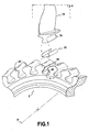
- a rotor disk 2 having at its periphery numerous grooves, or cells 4, defining a housing capable of receiving the foot 16 of a blade 14, this foot 16 being surrounded by a foil 20.
- the foot vane 16 and the fan disk 2 are made, for example, of titanium alloy.
- assemblies further comprising a wedge placed between the blade root 16 and the bottom of the cell 4.
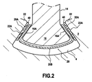
- the blades 14 are subjected to centrifugal forces and the bearings 16A of the blade roots 16 come to abut against the bearings 22A of the disk 2.
- the bearings 16A are the flanks of the dawn feet 16, while the bearing surfaces 22A are the faces lower portions of the lip-shaped disc 22 which surround the outer opening of the cells 4.
- the foil 20 comprises two lateral branches 20A intended to come against the bearings 16A of the blade root 16, and a base 20B (in this case in the form of a plate) connecting these branches to each other and extending under the blade root 16
- Each branch 20A is made of a first material having a first Young's modulus of value E at any temperature in the operating temperature range of the foil.
- the foil 20 is a wear part and its main function is to limit the wear of the blade root 16 and the fan disk 2.
- the foil 20 must have a certain rigidity in order to ensure its mechanical strength and its function antiwear.
- the value E is preferably greater than or equal to 110 000 MPa for a metal foil (for example: 210 000 MPa for a foil in a Nickel base superalloy, of the type marketed under the name "Inconel”) and greater than or equal to 70,000 MPa for a foil made of organic matrix composite material.
- the rotor assembly comprises platelets 40 adhering to the bearings 22A of the disc, these plates 40 being made of a second material having a second Young's modulus of value between E / 20 and E / 5 at said temperature.
- plates are fixed on the bearing surfaces 16A of the blade root, or on the bearing surfaces 22A of the disc and on the bearing surfaces 16A of the blade root.
- the rotor assembly belongs to the blower or the low pressure compressor of a twin-body, dual-flow aircraft turbojet engine, it is subjected to operating temperatures ranging from 20 to 150 ° C.
- the first material a base Ni superalloy with more than 15% by weight of Fe and Cr, such as the superalloy marketed under the name "Inconel 718"; and as the second rubber material (natural or synthetic).
- the first material a composite material with an epoxy resin matrix and reinforcing fibers, for example carbon fibers; and as the second material an epoxy resin alone (the difference in Young's modulus between the second and the first material being related to the absence of fibers).
- the assembly belongs to the high-pressure compressor of a twin-body, double-flow aircraft turbojet, it is subjected to an operating temperature ranging between 150 and 500 ° C.
- the first material a base Ni superalloy with more than 15% by weight of Fe and Cr, such as the superalloy marketed under the name "Inconel 718"; and as a second material a silicone or a polyimide.
- the assembly belongs to the high-pressure turbine of a twin-body, double-flow aircraft turbojet, it is subjected to an operating temperature ranging between 400 and 700 ° C.
- an operating temperature ranging between 400 and 700 ° C.
- the first material a base Ni superalloy with more than 15% by weight of Fe and Cr, such as the superalloy marketed under the name "Inconel 718"; and as the second glass material (which in this operating temperature range has a viscoelastic behavior).
- the fastening obtained must be sufficient to prevent the plates 40 from detaching the bearing surfaces 22A in operation.
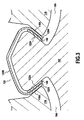
- FIG 3 is a sectional view similar to that of the figure 2 showing (partially) another example of a rotor assembly 120 according to the invention. Elements or similar parts of elements between figures 2 and 3 are identified by the same numerical references increased by 100.
- figure 3 differs from that of the figure 2 in that the base 120B of the foil 220 extends on the outer periphery of the rotor disc 202, between two adjacent cells 204, while each branch 120A of the foil enters a cavity 204 and is housed between the bearing surface 216A of the blade root 216 and the corresponding scope 222A of the disk 202.
- the position of the wafers 140 remains the same.
Landscapes
- Engineering & Computer Science (AREA)
- Mechanical Engineering (AREA)
- General Engineering & Computer Science (AREA)
- Structures Of Non-Positive Displacement Pumps (AREA)
- Turbine Rotor Nozzle Sealing (AREA)
- Gasket Seals (AREA)
Claims (6)
- Rotoranordnung einer Turbomaschine, umfassend eine Rotorscheibe (2), die an ihrem Außenumfang Zellen (4) aufweist, Schaufeln (14), die über ihren Fuß (16) in den Zellen (4) befestigt sind, sowie Zwischenstücke (20), die zwischen den Schaufelfüßen (16) und der Scheibe (2) angeordnet sind, wobei jedes Zwischenstück (20) zwei Schenkel (20A) und eine diese Schenkel untereinander verbindende Basis (20B) aufweist, wobei jeder Schenkel (20A) zwischen der Auflagefläche (16A) eines Schaufelfußes (16) und der entsprechenden Auflagefläche (22A) der Scheibe (2) angeordnet ist, und wobei jeder Schenkel (20A) aus einem ersten Werkstoff ausgebildet ist, der einen ersten Elastizitätsmodul mit dem Wert E, bei einer beliebigen Betriebstemperatur im Betriebstemperaturenbereich des Zwischenstücks (20) aufweist, wobei diese Rotoranordnung Platten (40) umfaßt, die an den Auflageflächen (22A) der Scheibe und/oder an den Auflageflächen (16A) des Schaufelfußes haften, dadurch gekennzeichnet, daß die Platten (40) aus einem zweiten Werkstoff ausgebildet sind, der einen zweiten Elastizitätsmodul mit einem Wert im Bereich zwischen E/20 und E/5 bei der Betriebstemperatur aufweist.
- Rotoranordnung nach Anspruch 1, wobei der erste Werkstoff eine Metallegierung oder ein Verbundwerkstoff mit organischer Matrix ist, während der zweite Werkstoff ein nichtmetallischer Werkstoff ist.
- Rotoranordnung nach Anspruch 1 oder 2, wobei der zweite Werkstoff ein viskoelastisches Verhalten in dem Betriebstemperaturenbereich des Zwischenstücks aufweist.
- Rotoranordnung nach einem der Ansprüche 1 bis 3, wobei die Basis (20B) eines jeden Zwischenstücks (20) unter einem Schaufelfuß (16) verläuft.
- Rotoranordnung nach einem der Ansprüche 1 bis 3, wobei die Basis (120B) eines jeden Zwischenstücks (120) sich über den Außenumfang der Scheibe (102), zwischen zwei benachbarten Zellen (104) erstreckt.
- Turbomaschine, die eine Rotoranordnung nach einem der Ansprüche 1 bis 5 umfaßt.
Applications Claiming Priority (1)
| Application Number | Priority Date | Filing Date | Title |
|---|---|---|---|
| FR0756467A FR2918703B1 (fr) | 2007-07-13 | 2007-07-13 | Ensemble de rotor de turbomachine |
Publications (2)
| Publication Number | Publication Date |
|---|---|
| EP2014874A1 EP2014874A1 (de) | 2009-01-14 |
| EP2014874B1 true EP2014874B1 (de) | 2011-03-16 |
Family
ID=39106159
Family Applications (1)
| Application Number | Title | Priority Date | Filing Date |
|---|---|---|---|
| EP08160249A Active EP2014874B1 (de) | 2007-07-13 | 2008-07-11 | Laufradeinheit eines Turbotriebwerks |
Country Status (8)
| Country | Link |
|---|---|
| US (1) | US20090016890A1 (de) |
| EP (1) | EP2014874B1 (de) |
| JP (1) | JP2009019630A (de) |
| CN (1) | CN101344013B (de) |
| CA (1) | CA2636924A1 (de) |
| DE (1) | DE602008005524D1 (de) |
| FR (1) | FR2918703B1 (de) |
| RU (1) | RU2465464C2 (de) |
Families Citing this family (33)
| Publication number | Priority date | Publication date | Assignee | Title |
|---|---|---|---|---|
| FR2945074B1 (fr) * | 2009-04-29 | 2011-06-03 | Snecma | Cale d'aube de soufflante renforcee |
| US8251667B2 (en) * | 2009-05-20 | 2012-08-28 | General Electric Company | Low stress circumferential dovetail attachment for rotor blades |
| GB201106050D0 (en) * | 2011-04-11 | 2011-05-25 | Rolls Royce Plc | A retention device for a composite blade of a gas turbine engine |
| GB201106276D0 (en) * | 2011-04-14 | 2011-05-25 | Rolls Royce Plc | Annulus filler system |
| US8740573B2 (en) * | 2011-04-26 | 2014-06-03 | General Electric Company | Adaptor assembly for coupling turbine blades to rotor disks |
| FR2981132B1 (fr) * | 2011-10-10 | 2013-12-06 | Snecma | Ensemble pour turbomachine a refroidissement de disque |
| US9611746B2 (en) * | 2012-03-26 | 2017-04-04 | United Technologies Corporation | Blade wedge attachment |
| FR2995003B1 (fr) | 2012-09-03 | 2014-08-15 | Snecma | Rotor de turbine pour une turbomachine |
| US10273816B2 (en) * | 2013-02-12 | 2019-04-30 | United Technologies Corporation | Wear pad to prevent cracking of fan blade |
| US9745856B2 (en) | 2013-03-13 | 2017-08-29 | Rolls-Royce Corporation | Platform for ceramic matrix composite turbine blades |
| WO2014143305A1 (en) * | 2013-03-14 | 2014-09-18 | United Technologies Corporation | Low speed fan for gas turbine engines |
| WO2014143364A2 (en) * | 2013-03-14 | 2014-09-18 | United Technologies Corporation | Co-formed element with low conductivity layer |
| US9506356B2 (en) | 2013-03-15 | 2016-11-29 | Rolls-Royce North American Technologies, Inc. | Composite retention feature |
| BR112015028251A2 (pt) * | 2013-05-29 | 2017-07-25 | Gen Electric | aerofólio compósito |
| US20150192144A1 (en) * | 2014-01-08 | 2015-07-09 | United Technologies Corporation | Fan Assembly With Fan Blade Under-Root Spacer |
| GB201411182D0 (en) * | 2014-06-24 | 2014-08-06 | Rolls Royce Plc | Rotor blade manufacture |
| CN104500446A (zh) * | 2014-12-14 | 2015-04-08 | 惠阳航空螺旋桨有限责任公司 | 风洞轴流压缩机转子复合材料叶片根部连接结构 |
| CN104500447A (zh) * | 2014-12-14 | 2015-04-08 | 惠阳航空螺旋桨有限责任公司 | 风洞轴流压缩机风扇 |
| US10093586B2 (en) | 2015-02-26 | 2018-10-09 | General Electric Company | Ceramic matrix composite articles and methods for forming same |
| CN107923251B (zh) * | 2015-08-19 | 2020-09-08 | 西门子公司 | 在叶片根部区域中具有抗微振磨损的覆层的燃气轮机叶片或者压缩机叶片和转子 |
| US10514004B2 (en) * | 2015-12-14 | 2019-12-24 | Rohr, Inc. | Cascade assembly for a thrust reverser of an aircraft nacelle |
| US10605100B2 (en) * | 2017-05-24 | 2020-03-31 | General Electric Company | Ceramic matrix composite (CMC) turbine blade assembly, dovetail sleeve, and method of mounting CMC turbine blade |
| US10767498B2 (en) | 2018-04-03 | 2020-09-08 | Rolls-Royce High Temperature Composites Inc. | Turbine disk with pinned platforms |
| US10890081B2 (en) | 2018-04-23 | 2021-01-12 | Rolls-Royce Corporation | Turbine disk with platforms coupled to disk |
| US10577961B2 (en) | 2018-04-23 | 2020-03-03 | Rolls-Royce High Temperature Composites Inc. | Turbine disk with blade supported platforms |
| ES2950768T3 (es) | 2018-05-11 | 2023-10-13 | Carrier Corp | Sistema de detección por resonancia de plasmones de superficie |
| JP7236316B2 (ja) * | 2019-04-17 | 2023-03-09 | 三菱重工業株式会社 | 複合材翼及び複合材翼の成形方法 |
| FR3099213B1 (fr) * | 2019-07-23 | 2021-07-16 | Safran Aircraft Engines | Rotor de soufflante pour une turbomachine d’aeronef |
| CN111022126A (zh) * | 2019-11-19 | 2020-04-17 | 中国航发沈阳黎明航空发动机有限责任公司 | 一种转子密封减振结构 |
| FR3121476B1 (fr) * | 2021-04-01 | 2024-01-12 | Safran Aircraft Engines | Clinquant pour aube mobile de turbomachine et ensemble pour rotor comportant un tel clinquant |
| FR3133640A1 (fr) * | 2022-03-18 | 2023-09-22 | Safran Aircraft Engines | Procédé de maintenance d’une roue aubagée de turbine haute pression d’une turbomachine |
| EP4386193B1 (de) * | 2022-12-16 | 2025-01-01 | Rolls-Royce plc | Wärmeverwaltungssystem für gasturbinenmotor |
| EP4603379A1 (de) | 2024-02-14 | 2025-08-20 | General Electric Company | Verbundschaufelanordnung mit einer verbundschaufel und holm |
Family Cites Families (24)
| Publication number | Priority date | Publication date | Assignee | Title |
|---|---|---|---|---|
| GB709636A (en) * | 1951-05-09 | 1954-06-02 | Rolls Royce | Improvements in or relating to compressor and turbine bladed rotors |
| US2874932A (en) * | 1952-02-25 | 1959-02-24 | Maschf Augsburg Nuernberg Ag | Steel turbine rotors with ceramic blades |
| US2950083A (en) * | 1954-07-23 | 1960-08-23 | Thompson Ramo Wooldridge Inc | Blade assembly |
| DE2108176A1 (de) * | 1971-02-20 | 1972-08-31 | Motoren Turbinen Union | Befestigung von keramischen Turbinenschaufeln |
| SU595521A1 (ru) * | 1976-10-08 | 1978-02-28 | Научно-производственное объединение по технологии машиностроения | Рабочее колесо турбомашины |
| US4169694A (en) * | 1977-07-20 | 1979-10-02 | Electric Power Research Institute, Inc. | Ceramic rotor blade having root with double curvature |
| US4207029A (en) * | 1978-06-12 | 1980-06-10 | Avco Corporation | Turbine rotor assembly of ceramic blades to metallic disc |
| JPS62113804A (ja) * | 1985-11-13 | 1987-05-25 | Toshiba Corp | 蒸気タ−ビン |
| DE3815977A1 (de) * | 1988-05-10 | 1989-11-30 | Mtu Muenchen Gmbh | Folienzwischenlage zur fuegung von reibkorrosionsgefaehrdeten maschinenbauteilen |
| JP2718131B2 (ja) * | 1989-01-23 | 1998-02-25 | 石川島播磨重工業株式会社 | ガスタービンディスク |
| US5087174A (en) * | 1990-01-22 | 1992-02-11 | Westinghouse Electric Corp. | Temperature activated expanding mineral shim |
| US5160243A (en) * | 1991-01-15 | 1992-11-03 | General Electric Company | Turbine blade wear protection system with multilayer shim |
| US5240375A (en) * | 1992-01-10 | 1993-08-31 | General Electric Company | Wear protection system for turbine engine rotor and blade |
| FR2699498B1 (fr) * | 1992-12-23 | 1995-03-10 | Eurocopter France | Pale en composite thermoplastique, notamment pour rotor arrière caréné d'hélicoptère, et son procédé de fabrication. |
| JPH07247804A (ja) * | 1993-01-07 | 1995-09-26 | General Electric Co <Ge> | ガスタービンエンジン用のロータ及び動翼アセンブリ、並びに多層被覆シム |
| JP3216956B2 (ja) * | 1994-06-08 | 2001-10-09 | 株式会社日立製作所 | ガスタービン翼固定装置 |
| WO1996041068A1 (en) * | 1995-06-07 | 1996-12-19 | National Research Council Of Canada | Anti-fretting barrier |
| US6132175A (en) * | 1997-05-29 | 2000-10-17 | Alliedsignal, Inc. | Compliant sleeve for ceramic turbine blades |
| US6290466B1 (en) * | 1999-09-17 | 2001-09-18 | General Electric Company | Composite blade root attachment |
| US6431835B1 (en) * | 2000-10-17 | 2002-08-13 | Honeywell International, Inc. | Fan blade compliant shim |
| US6751863B2 (en) * | 2002-05-07 | 2004-06-22 | General Electric Company | Method for providing a rotating structure having a wire-arc-sprayed aluminum bronze protective coating thereon |
| US6860722B2 (en) * | 2003-01-31 | 2005-03-01 | General Electric Company | Snap on blade shim |
| FR2890126B1 (fr) * | 2005-08-26 | 2010-10-29 | Snecma | Ensemble et procede pour le montage du pied d'une aube de turbomachine, soufflante, compresseur et turbomachine comportant un tel ensemble |
| FR2890684B1 (fr) * | 2005-09-15 | 2007-12-07 | Snecma | Clinquant pour aube de turboreacteur |
-
2007
- 2007-07-13 FR FR0756467A patent/FR2918703B1/fr not_active Expired - Fee Related
-
2008
- 2008-07-10 CA CA002636924A patent/CA2636924A1/fr not_active Abandoned
- 2008-07-11 DE DE602008005524T patent/DE602008005524D1/de active Active
- 2008-07-11 US US12/171,775 patent/US20090016890A1/en not_active Abandoned
- 2008-07-11 RU RU2008128359/06A patent/RU2465464C2/ru active
- 2008-07-11 EP EP08160249A patent/EP2014874B1/de active Active
- 2008-07-11 JP JP2008181059A patent/JP2009019630A/ja active Pending
- 2008-07-14 CN CN2008101379626A patent/CN101344013B/zh active Active
Also Published As
| Publication number | Publication date |
|---|---|
| DE602008005524D1 (de) | 2011-04-28 |
| CA2636924A1 (fr) | 2009-01-13 |
| FR2918703B1 (fr) | 2009-10-16 |
| RU2465464C2 (ru) | 2012-10-27 |
| RU2008128359A (ru) | 2010-01-20 |
| EP2014874A1 (de) | 2009-01-14 |
| US20090016890A1 (en) | 2009-01-15 |
| JP2009019630A (ja) | 2009-01-29 |
| CN101344013B (zh) | 2013-11-06 |
| FR2918703A1 (fr) | 2009-01-16 |
| CN101344013A (zh) | 2009-01-14 |
Similar Documents
| Publication | Publication Date | Title |
|---|---|---|
| EP2014874B1 (de) | Laufradeinheit eines Turbotriebwerks | |
| EP2014873B1 (de) | Metallfolie für Laufradschaufel eines Turbotriebwerks | |
| EP1870562B1 (de) | Gleichrichtersegment eines Kompressors oder Verteilersegment einer Strömungsmaschine | |
| CA2732032C (fr) | Dispositif amortisseur de vibrations pour attaches d'aubes de turbomachine, turbomachine et moteurs associes | |
| EP2009242B1 (de) | Stoßdämpfervorrichtung für Stator eines Turbotriebwerks | |
| EP2459884B1 (de) | Aussenhüllenabschnitt für einen beschaufelten statorring eines flugzeugtriebwerks mit schwingungsdämpfenden blöcken | |
| EP3820684B1 (de) | Schaufel aus verbundwerkstoff mit verbesserter erosionsschutzfolie und zugehöriges schutzverfahren | |
| FR2941487A1 (fr) | Aube de turbomachine en materiau composite a pied renforce | |
| FR2943102A1 (fr) | Aube en materiau composite comportant un dispositif d'amortissement. | |
| FR2978798A1 (fr) | Secteur angulaire de redresseur de turbomachine a amortissement des modes de vibrations | |
| FR2965843A1 (fr) | Rotor pour turbomachine | |
| EP4413238B1 (de) | Turbinenschaufel eines turbinenmotors mit im betrieb selbsterzeugter verriegelungskontaktkraft | |
| FR3130906A1 (fr) | Rotor de turbomachine | |
| FR3075253B1 (fr) | Dispositif amortisseur | |
| FR3049643A1 (fr) | Roue a pales rapportees et turbomachine equipee d'une telle roue | |
| EP4544155A1 (de) | Schaufelanordnung für eine turbomaschine, turbine für eine turbomaschine und turbomaschine | |
| FR2962481A1 (fr) | Amortisseur de vibrations a bras de levier pour aube d'un rotor de moteur a turbine a gaz | |
| FR3108665A1 (fr) | Rotor de soufflante comprenant des aubes à centre de gravité en amont | |
| EP3976929A1 (de) | Anordnung für eine turbomaschine | |
| FR3160995A1 (fr) | Aube comprenant un insert de protection du pied d’aube, soufflante et procédé associé. | |
| FR2946400A1 (fr) | Disque de rotor, en particulier de soufflante, pour turbomachine | |
| FR3108664A1 (fr) | Rotor de soufflante comprenant des aubes à centre de gravité en amont | |
| EP4396445A1 (de) | Dämpfungsvorrichtung für ein rotorrad eines flugzeugturbinentriebwerks, rotorrad für ein flugzeugturbinentriebwerk, turbinentriebwerk für ein flugzeug und verfahren zur herstellung einer dämpfungsvorrichtung |
Legal Events
| Date | Code | Title | Description |
|---|---|---|---|
| PUAI | Public reference made under article 153(3) epc to a published international application that has entered the european phase |
Free format text: ORIGINAL CODE: 0009012 |
|
| 17P | Request for examination filed |
Effective date: 20080711 |
|
| AK | Designated contracting states |
Kind code of ref document: A1 Designated state(s): AT BE BG CH CY CZ DE DK EE ES FI FR GB GR HR HU IE IS IT LI LT LU LV MC MT NL NO PL PT RO SE SI SK TR |
|
| AX | Request for extension of the european patent |
Extension state: AL BA MK RS |
|
| AKX | Designation fees paid |
Designated state(s): DE FR GB SE |
|
| GRAP | Despatch of communication of intention to grant a patent |
Free format text: ORIGINAL CODE: EPIDOSNIGR1 |
|
| GRAS | Grant fee paid |
Free format text: ORIGINAL CODE: EPIDOSNIGR3 |
|
| GRAA | (expected) grant |
Free format text: ORIGINAL CODE: 0009210 |
|
| AK | Designated contracting states |
Kind code of ref document: B1 Designated state(s): DE FR GB SE |
|
| REG | Reference to a national code |
Ref country code: GB Ref legal event code: FG4D Free format text: NOT ENGLISH |
|
| REF | Corresponds to: |
Ref document number: 602008005524 Country of ref document: DE Date of ref document: 20110428 Kind code of ref document: P |
|
| REG | Reference to a national code |
Ref country code: DE Ref legal event code: R096 Ref document number: 602008005524 Country of ref document: DE Effective date: 20110428 |
|
| REG | Reference to a national code |
Ref country code: SE Ref legal event code: TRGR |
|
| PLBE | No opposition filed within time limit |
Free format text: ORIGINAL CODE: 0009261 |
|
| STAA | Information on the status of an ep patent application or granted ep patent |
Free format text: STATUS: NO OPPOSITION FILED WITHIN TIME LIMIT |
|
| 26N | No opposition filed |
Effective date: 20111219 |
|
| REG | Reference to a national code |
Ref country code: DE Ref legal event code: R097 Ref document number: 602008005524 Country of ref document: DE Effective date: 20111219 |
|
| REG | Reference to a national code |
Ref country code: FR Ref legal event code: PLFP Year of fee payment: 9 |
|
| REG | Reference to a national code |
Ref country code: FR Ref legal event code: PLFP Year of fee payment: 10 |
|
| REG | Reference to a national code |
Ref country code: FR Ref legal event code: CD Owner name: SAFRAN AIRCRAFT ENGINES, FR Effective date: 20170717 |
|
| REG | Reference to a national code |
Ref country code: FR Ref legal event code: PLFP Year of fee payment: 11 |
|
| PGFP | Annual fee paid to national office [announced via postgrant information from national office to epo] |
Ref country code: DE Payment date: 20250722 Year of fee payment: 18 |
|
| PGFP | Annual fee paid to national office [announced via postgrant information from national office to epo] |
Ref country code: GB Payment date: 20250724 Year of fee payment: 18 |
|
| PGFP | Annual fee paid to national office [announced via postgrant information from national office to epo] |
Ref country code: FR Payment date: 20250722 Year of fee payment: 18 |
|
| PGFP | Annual fee paid to national office [announced via postgrant information from national office to epo] |
Ref country code: SE Payment date: 20250723 Year of fee payment: 18 |