EP2014878A2 - Vorbelastete Klammer für den Transport von Gasturbinen - Google Patents
Vorbelastete Klammer für den Transport von Gasturbinen Download PDFInfo
- Publication number
- EP2014878A2 EP2014878A2 EP08252392A EP08252392A EP2014878A2 EP 2014878 A2 EP2014878 A2 EP 2014878A2 EP 08252392 A EP08252392 A EP 08252392A EP 08252392 A EP08252392 A EP 08252392A EP 2014878 A2 EP2014878 A2 EP 2014878A2
- Authority
- EP
- European Patent Office
- Prior art keywords
- engine
- shaft
- fan
- brace
- bearings
- Prior art date
- Legal status (The legal status is an assumption and is not a legal conclusion. Google has not performed a legal analysis and makes no representation as to the accuracy of the status listed.)
- Withdrawn
Links
- 238000005096 rolling process Methods 0.000 claims description 13
- 238000000034 method Methods 0.000 claims description 11
- 230000003068 static effect Effects 0.000 claims description 11
- 238000004806 packaging method and process Methods 0.000 claims description 2
- 239000007789 gas Substances 0.000 description 19
- 238000012546 transfer Methods 0.000 description 14
- 230000035939 shock Effects 0.000 description 7
- 239000000463 material Substances 0.000 description 5
- 230000007547 defect Effects 0.000 description 4
- 230000036316 preload Effects 0.000 description 3
- 239000003570 air Substances 0.000 description 2
- 239000000567 combustion gas Substances 0.000 description 2
- 238000012986 modification Methods 0.000 description 2
- 230000004048 modification Effects 0.000 description 2
- 239000012080 ambient air Substances 0.000 description 1
- 238000004891 communication Methods 0.000 description 1
- 239000000446 fuel Substances 0.000 description 1
- 238000007373 indentation Methods 0.000 description 1
- 238000009434 installation Methods 0.000 description 1
- 238000004519 manufacturing process Methods 0.000 description 1
- 230000002028 premature Effects 0.000 description 1
- 230000002265 prevention Effects 0.000 description 1
- 239000012858 resilient material Substances 0.000 description 1
- 238000012552 review Methods 0.000 description 1
- 239000008261 styrofoam Substances 0.000 description 1
Images


Classifications
-
- F—MECHANICAL ENGINEERING; LIGHTING; HEATING; WEAPONS; BLASTING
- F01—MACHINES OR ENGINES IN GENERAL; ENGINE PLANTS IN GENERAL; STEAM ENGINES
- F01D—NON-POSITIVE DISPLACEMENT MACHINES OR ENGINES, e.g. STEAM TURBINES
- F01D25/00—Component parts, details, or accessories, not provided for in, or of interest apart from, other groups
- F01D25/28—Supporting or mounting arrangements, e.g. for turbine casing
- F01D25/285—Temporary support structures, e.g. for testing, assembling, installing, repairing; Assembly methods using such structures
-
- F—MECHANICAL ENGINEERING; LIGHTING; HEATING; WEAPONS; BLASTING
- F16—ENGINEERING ELEMENTS AND UNITS; GENERAL MEASURES FOR PRODUCING AND MAINTAINING EFFECTIVE FUNCTIONING OF MACHINES OR INSTALLATIONS; THERMAL INSULATION IN GENERAL
- F16C—SHAFTS; FLEXIBLE SHAFTS; ELEMENTS OR CRANKSHAFT MECHANISMS; ROTARY BODIES OTHER THAN GEARING ELEMENTS; BEARINGS
- F16C41/00—Other accessories, e.g. devices integrated in the bearing not relating to the bearing function as such
- F16C41/04—Preventing damage to bearings during storage or transport thereof or when otherwise out of use
Definitions
- the invention relates generally to gas turbine engines and, more particularly, to the prevention of engine bearing damage caused during the transportation of gas turbine engines.
- shock loading can occur during an impact, a drop or abrupt back and forth movements.
- the engine rotor is not rotating and the engine bearings are supporting the weight of the rotor, only a few rolling elements are in contact with the raceways. In some cases, only two or three rolling elements may be in contact with the raceway of a particular bearing. Therefore, due to the relatively small contact area between the rolling elements and the raceway, a shock load while transporting the engine may result in a very high contact pressure between the rolling elements and the raceway which can be beyond the material's elasticity limit.
- True brinelling defects are characterised by indentations or material deformations on the raceway which are of the shape of the contact area between the rolling elements and the raceway, and, are spaced according to the rolling element spacing.
- True brinelling defects in a bearing raceway can lead to vibrations and noisy engines particularly at slower rotational speeds or at run down and can lead to premature failure of the bearing.
- Conventional ball bearings are typically more prone to true brinelling damage, however this type of damage can also occur in roller bearings or the like.
- an assembly comprising: a turbofan gas turbine engine, the engine having an engine casing and at least one turbine shaft supported by a plurality of bearings, the bearings having a static portion mounted to the casing; a brace secured relative to the engine casing and disposed in contact with a rotating member of the engine mounted to the shaft, the brace biasing the shaft along an axial direction of the shaft.
- an assembly comprising: a turbofan gas turbine engine having a fan mounted to a fan shaft, the fan shaft being supported on bearings and the bearings being secured to an engine casing; and means for axially biasing the fan shaft relative to the engine casing.
- a method for transporting a turbofan gas turbine engine wherein the engine comprises a turbine shaft having a rotating member mounted thereto, the shaft being supported by a plurality of bearings, the engine having a casing to which a static portion of the bearings are mounted, the method comprising the steps of: a) exerting a force on the shaft in relation to the static portion of the bearings, the force being exerted along a central axis of the shaft; b) transporting the engine; and c) removing the force on the shaft prior to the operation of the engine.
- Fig. 1 illustrates a turbofan gas turbine engine 10 of a type preferably provided for use in subsonic flight, generally comprising in serial flow communication a fan 12 through which ambient air is drawn, a multistage compressor 14 for pressurizing the air, a combustor 16 in which the compressed air is mixed with fuel and ignited for generating an annular stream of hot combustion gases, and a turbine section 18 for extracting energy from the combustion gases.
- the fan 12 is a rotating member of the gas turbine engine 10 and is disposed within a static fan case 20 which defines a fan inlet.
- the fan 12 is secured to a main shaft 22 which is supported within the engine 10 by a plurality of engine bearings which are not shown.
- the fan 12 and the shaft 22 have a common central axis of rotation 23.
- the types of bearings that are used to support the shaft 22 typically comprise rolling elements and a raceway disposed on a static portion of the bearing that is mounted to a static casing of the engine. These types of bearings may experience true brinelling damage when subjected to significant shock loading during, for example, transportation of the engine 10.
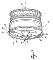
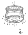
- Fig. 2 shows a brace 24 that is removably secured to the fan case 20.
- the brace 24 comprises a bracing member 26 and a load transfer member 28 disposed on the bracing member 26.
- a front view and a side view of the bracing member 26 are shown in Figs. 3 and 4 respectively.
- the bracing member 26 has two mounting portions 30 wherein each mounting portion 30 has one or more holes 32 that are used to secure the bracing member 26 to the fan case 20.
- the two mounting portions 30 are located at opposite ends of the bracing member 26.
- the bracing member 26 also comprises a holding portion 34 on which the load transfer member 28 is disposed.
- the holding portion 34 is located approximately mid-span between the two mounting portions 30.
- Fig. 5 shows another brace 24 wherein the mounting portions 30 are adapted to be secured to a fan case 20 having a different configuration.
- the brace 24 is removably secured to the fan case 20 prior to the transport of the gas turbine engine 10 in order to prevent or reduce damage to the engine bearings, especially true brinelling defects, caused by shock loading.
- the bracing member 26 is secured to the fan case 20 by fastening the mounting portions 30 to a flange 36 of the fan case 20 using bolts 38.
- the brace 24 is installed and the gas turbine engine 10 may be packaged or prepared in accordance with conventional procedures.
- the brace 24 is intended to be reusable and must be removed prior to the operation of the gas turbine engine 10.
- the holding portion 34 of the bracing member 26 urges the load transfer member 28 against a nose cone 40 of the fan 12.
- the nose cone 40 is shown in Figs. 2 and 5 for clarity. Accordingly, an axial preloading force is applied to the fan 12 in a direction parallel to the central axis of rotation 23 and transferred to the bearings via the shaft 22.
- This axial force causes all the rolling elements of one or more bearings supporting the shaft 22 to become seated against their respective raceway. Since all the rolling elements of the bearing are kept in contact with the raceway, a larger contact area is provided for transmitting the forces induced by shock loading during transportation of the gas turbine engine 10.
- the true brinelling damage that can occur during engine transportation when only a few rolling elements are in contact with the raceway, is prevented or significantly reduced. Consequently, the installation of the brace 24 also limits the unwanted movement of the fan relative to the fan case 20.
- the load transfer member 28 transfers the axial load from the bracing member 26 to the nose cone 40 of the fan 12 by pushing against the nose cone 40 and thereby biasing the shaft along a downstream direction relative to the turbine engine 10.
- the direction in which the axial force should be applied to the fan 12 along the central axis 23 will depend on the type of bearings that are used to support the shaft 22. In any case, the magnitude of the axial preloading force should be sufficient to cause all the rolling elements of at least one bearing to become seated against the raceway. Typically, the preload force required ranges from 30 lbs to 100 lbs for an engine of the type shown in Fig. 1 .
- the load transfer member 28 may be ring-shaped to receive the nose cone 40 of the fan 12 and may comprise a resilient and/or compressible material which allows the load transfer member 28 to be held in a compressed state against the nose cone 40 of the fan 12.
- the spacing between the bracing member 26 and the nose cone 40 may be such that when the bracing member 26 is installed, the load transfer member 28 is in a compressed state and therefore urges the nose cone 40 of the fan 12 away from the bracing member 26.
- Suitable materials that may be used for the load transfer member 28 are for example Styrofoam TM , rubber or the like.
- the load transfer member 28 may be affixed to the bracing member 26 or may be separate and simply compressed between the bracing member 26 and the nose cone 40. It will be apparent to one skilled in the art that other configurations of load transfer members could also be used. For example a springloaded pad urging the fan 12 away from the bracing member 26 would achieve similar results.
- the bracing member 26 itself may be designed to be flexible and resilient.
- the bracing member 26 would be secured to the fan case 20 in a deflected or biased state and would thereby urge the load transfer member 28 against the nose cone 40 of the fan 12 in order to exert a suitable axial preload force.
- the above description is meant to be exemplary only, and one skilled in the art will recognize that changes may be made to the embodiments described without department from the scope of the invention disclosed. For example, it is apparent that providing a brace that is adapted to be secured to a static component or casing of the gas turbine engine 10 other than the fan case 20 is also feasible.
- the brace could also be secured to or form part of a shipping container in which the gas turbine engine is packaged during transportation in order to exert an axial force on the shaft 22 relative to the static portion of the bearings. Further, the axial preload force could be transmitted to a different location on the fan 12 or to another rotating member mounted on the shaft 22 in order to cause the rolling elements of at least one bearing supporting the shaft 22 to become seated on the raceway. It is also apparent that the brace 24 described above can be fabricated using conventional manufacturing procedures using suitable materials that would be apparent to a person skilled in the relevant art.
- brace is not limited to turbofan gas turbine engines but could also be useful for the transport of other types of turbines or rotary machinery where similar brinelling damage to support bearings may be of concern. Still other modifications which fall within the scope of the present invention will be apparent to those skilled in the art, in light of a review of this disclosure, and such modifications are intended to fall within the appended claims.
Landscapes
- Engineering & Computer Science (AREA)
- General Engineering & Computer Science (AREA)
- Mechanical Engineering (AREA)
- Rolling Contact Bearings (AREA)
- Structures Of Non-Positive Displacement Pumps (AREA)
Applications Claiming Priority (1)
| Application Number | Priority Date | Filing Date | Title |
|---|---|---|---|
| US11/777,634 US7857578B2 (en) | 2007-07-13 | 2007-07-13 | Preloading brace for gas turbine engine transportation |
Publications (2)
| Publication Number | Publication Date |
|---|---|
| EP2014878A2 true EP2014878A2 (de) | 2009-01-14 |
| EP2014878A3 EP2014878A3 (de) | 2012-01-11 |
Family
ID=39717710
Family Applications (1)
| Application Number | Title | Priority Date | Filing Date |
|---|---|---|---|
| EP08252392A Withdrawn EP2014878A3 (de) | 2007-07-13 | 2008-07-14 | Vorbelastete Klammer für den Transport von Gasturbinen |
Country Status (4)
| Country | Link |
|---|---|
| US (1) | US7857578B2 (de) |
| EP (1) | EP2014878A3 (de) |
| CA (1) | CA2692712C (de) |
| WO (1) | WO2009009864A1 (de) |
Cited By (3)
| Publication number | Priority date | Publication date | Assignee | Title |
|---|---|---|---|---|
| EP2743510A4 (de) * | 2011-08-08 | 2015-08-19 | Mitsubishi Heavy Ind Compressor Corp | Form zur verwendung in einer rotationsmaschine und verfahren zum transport der rotationsmaschine |
| EP3537573A1 (de) * | 2018-03-06 | 2019-09-11 | Traktionssysteme Austria GmbH | Fixierelement zur fixierung der rotorwelle einer elektrischen maschine an dessen stator, sowie elektrische maschine mit einem solchen fixierelement |
| WO2024126921A1 (fr) * | 2022-12-16 | 2024-06-20 | Safran Nacelles | Outillage de manutention d'un capot d'entrée de turbomachine d'aéronef |
Families Citing this family (5)
| Publication number | Priority date | Publication date | Assignee | Title |
|---|---|---|---|---|
| US9261112B2 (en) | 2012-04-24 | 2016-02-16 | General Electric Company | Dampers for fan spinners of aircraft engines |
| EP2971613B1 (de) | 2013-03-13 | 2020-10-07 | United Technologies Corporation | Träger für nasenhaube |
| US10323770B2 (en) * | 2015-10-12 | 2019-06-18 | Emerson Process Management Regulator Technologies, Inc. | Control member for a fluid control device |
| US11767772B1 (en) * | 2022-04-18 | 2023-09-26 | Pratt & Whitney Canada Corp. | Passively rotating a rotating structure of a gas turbine engine during transportation |
| US20260098487A1 (en) * | 2024-10-04 | 2026-04-09 | Pratt & Whitney Canada Corp. | Rotor bearing loading mechanism |
Family Cites Families (7)
| Publication number | Priority date | Publication date | Assignee | Title |
|---|---|---|---|---|
| FR2557541B1 (fr) * | 1983-12-29 | 1986-09-19 | Snecma | Bati de transport de turbomachine |
| US4668109A (en) | 1986-07-31 | 1987-05-26 | Basso Robert J | Journal with spring loaded bearings |
| NZ241415A (en) * | 1992-01-27 | 1995-04-27 | Air New Zealand Ltd | Gas turbine engine transporting frames |
| US6098263A (en) * | 1997-10-27 | 2000-08-08 | Reliance Electric Technologies, Llc | Apparatus and method for blocking shaft of large scale rotatable assembly |
| US6170141B1 (en) * | 1998-09-25 | 2001-01-09 | Stanley Aviation Corporation | Shipping system for jet aircraft engine and method of installing and removing jet aircraft engine |
| US6883224B2 (en) * | 2002-02-01 | 2005-04-26 | Honeywell International Inc. | Gas turbine impeller alignment tool and method |
| US7103952B2 (en) * | 2004-03-12 | 2006-09-12 | The Boeing Company | Engine loader and transporter apparatus and methods |
-
2007
- 2007-07-13 US US11/777,634 patent/US7857578B2/en active Active
-
2008
- 2008-06-18 WO PCT/CA2008/001167 patent/WO2009009864A1/en not_active Ceased
- 2008-06-18 CA CA2692712A patent/CA2692712C/en not_active Expired - Fee Related
- 2008-07-14 EP EP08252392A patent/EP2014878A3/de not_active Withdrawn
Cited By (5)
| Publication number | Priority date | Publication date | Assignee | Title |
|---|---|---|---|---|
| EP2743510A4 (de) * | 2011-08-08 | 2015-08-19 | Mitsubishi Heavy Ind Compressor Corp | Form zur verwendung in einer rotationsmaschine und verfahren zum transport der rotationsmaschine |
| US9243645B2 (en) | 2011-08-08 | 2016-01-26 | Mitsubishi Heavy Industries Compressor Corporation | Fixture used in rotary machine and method for transporting rotary machine |
| EP3537573A1 (de) * | 2018-03-06 | 2019-09-11 | Traktionssysteme Austria GmbH | Fixierelement zur fixierung der rotorwelle einer elektrischen maschine an dessen stator, sowie elektrische maschine mit einem solchen fixierelement |
| WO2024126921A1 (fr) * | 2022-12-16 | 2024-06-20 | Safran Nacelles | Outillage de manutention d'un capot d'entrée de turbomachine d'aéronef |
| FR3143561A1 (fr) * | 2022-12-16 | 2024-06-21 | Safran Nacelles | Outillage de manutention d’un capot de turbomachine d’aéronef |
Also Published As
| Publication number | Publication date |
|---|---|
| EP2014878A3 (de) | 2012-01-11 |
| CA2692712C (en) | 2015-10-13 |
| US20090014609A1 (en) | 2009-01-15 |
| US7857578B2 (en) | 2010-12-28 |
| WO2009009864A1 (en) | 2009-01-22 |
| CA2692712A1 (en) | 2009-01-22 |
Similar Documents
| Publication | Publication Date | Title |
|---|---|---|
| CA2692712C (en) | Preloading brace for gas turbine engine transportation | |
| US10815825B2 (en) | Post FBO windmilling bumper | |
| CA2861291C (en) | Double frangible bearing support | |
| US8727629B2 (en) | Series bearing support apparatus for a gas turbine engine | |
| US8727632B2 (en) | Bearing support apparatus for a gas turbine engine | |
| US6491497B1 (en) | Method and apparatus for supporting rotor assemblies during unbalances | |
| US7731426B2 (en) | Rotor supports and systems | |
| US9657594B2 (en) | Gas turbine engine, machine and self-aligning foil bearing system | |
| EP3719266B1 (de) | Anordnung für eine lagerkammer eines gasturbinentriebwerks | |
| EP1900910B1 (de) | Schublagergehäuse für einen Gasturbinenmotor | |
| US8292509B2 (en) | Bearing arrangement | |
| JP2018087633A (ja) | ランディング軸受アセンブリおよびそのようなアセンブリが備わった回転機械 | |
| EP2942538B1 (de) | Mehrfachlager-stapelrückhaltung |
Legal Events
| Date | Code | Title | Description |
|---|---|---|---|
| PUAI | Public reference made under article 153(3) epc to a published international application that has entered the european phase |
Free format text: ORIGINAL CODE: 0009012 |
|
| AK | Designated contracting states |
Kind code of ref document: A2 Designated state(s): AT BE BG CH CY CZ DE DK EE ES FI FR GB GR HR HU IE IS IT LI LT LU LV MC MT NL NO PL PT RO SE SI SK TR |
|
| AX | Request for extension of the european patent |
Extension state: AL BA MK RS |
|
| RAP1 | Party data changed (applicant data changed or rights of an application transferred) |
Owner name: PRATT & WHITNEY CANADA CORP. |
|
| RIN1 | Information on inventor provided before grant (corrected) |
Inventor name: GIROUX, SYLVAIN Inventor name: BEAUVAIS, GILLES Inventor name: ISABEL, YVES Inventor name: URAC, TIBOR |
|
| PUAL | Search report despatched |
Free format text: ORIGINAL CODE: 0009013 |
|
| AK | Designated contracting states |
Kind code of ref document: A3 Designated state(s): AT BE BG CH CY CZ DE DK EE ES FI FR GB GR HR HU IE IS IT LI LT LU LV MC MT NL NO PL PT RO SE SI SK TR |
|
| AX | Request for extension of the european patent |
Extension state: AL BA MK RS |
|
| RIC1 | Information provided on ipc code assigned before grant |
Ipc: F01D 25/28 20060101AFI20111202BHEP |
|
| AKY | No designation fees paid | ||
| REG | Reference to a national code |
Ref country code: DE Ref legal event code: R108 |
|
| REG | Reference to a national code |
Ref country code: DE Ref legal event code: R108 Effective date: 20120919 |
|
| STAA | Information on the status of an ep patent application or granted ep patent |
Free format text: STATUS: THE APPLICATION IS DEEMED TO BE WITHDRAWN |
|
| 18D | Application deemed to be withdrawn |
Effective date: 20120712 |