EP2014907A1 - Rapsölmotor - Google Patents
Rapsölmotor Download PDFInfo
- Publication number
- EP2014907A1 EP2014907A1 EP08010661A EP08010661A EP2014907A1 EP 2014907 A1 EP2014907 A1 EP 2014907A1 EP 08010661 A EP08010661 A EP 08010661A EP 08010661 A EP08010661 A EP 08010661A EP 2014907 A1 EP2014907 A1 EP 2014907A1
- Authority
- EP
- European Patent Office
- Prior art keywords
- internal combustion
- combustion engine
- fuel
- switching valve
- assembly
- Prior art date
- Legal status (The legal status is an assumption and is not a legal conclusion. Google has not performed a legal analysis and makes no representation as to the accuracy of the status listed.)
- Granted
Links
- 239000000446 fuel Substances 0.000 claims abstract description 90
- 238000002485 combustion reaction Methods 0.000 claims abstract description 54
- 235000019484 Rapeseed oil Nutrition 0.000 claims abstract description 31
- 239000007788 liquid Substances 0.000 claims description 3
- 238000011045 prefiltration Methods 0.000 claims description 2
- 239000002283 diesel fuel Substances 0.000 description 13
- 238000002347 injection Methods 0.000 description 5
- 239000007924 injection Substances 0.000 description 5
- 238000001914 filtration Methods 0.000 description 2
- 230000000903 blocking effect Effects 0.000 description 1
- 238000001816 cooling Methods 0.000 description 1
- 230000000694 effects Effects 0.000 description 1
- 239000012530 fluid Substances 0.000 description 1
- 238000010438 heat treatment Methods 0.000 description 1
- 238000009434 installation Methods 0.000 description 1
- 238000000034 method Methods 0.000 description 1
- 235000019198 oils Nutrition 0.000 description 1
- 238000009420 retrofitting Methods 0.000 description 1
Images
Classifications
-
- F—MECHANICAL ENGINEERING; LIGHTING; HEATING; WEAPONS; BLASTING
- F02—COMBUSTION ENGINES; HOT-GAS OR COMBUSTION-PRODUCT ENGINE PLANTS
- F02M—SUPPLYING COMBUSTION ENGINES IN GENERAL WITH COMBUSTIBLE MIXTURES OR CONSTITUENTS THEREOF
- F02M37/00—Apparatus or systems for feeding liquid fuel from storage containers to carburettors or fuel-injection apparatus; Arrangements for purifying liquid fuel specially adapted for, or arranged on, internal-combustion engines
- F02M37/0047—Layout or arrangement of systems for feeding fuel
- F02M37/0064—Layout or arrangement of systems for feeding fuel for engines being fed with multiple fuels or fuels having special properties, e.g. bio-fuels; varying the fuel composition
-
- F—MECHANICAL ENGINEERING; LIGHTING; HEATING; WEAPONS; BLASTING
- F02—COMBUSTION ENGINES; HOT-GAS OR COMBUSTION-PRODUCT ENGINE PLANTS
- F02M—SUPPLYING COMBUSTION ENGINES IN GENERAL WITH COMBUSTIBLE MIXTURES OR CONSTITUENTS THEREOF
- F02M37/00—Apparatus or systems for feeding liquid fuel from storage containers to carburettors or fuel-injection apparatus; Arrangements for purifying liquid fuel specially adapted for, or arranged on, internal-combustion engines
- F02M37/0047—Layout or arrangement of systems for feeding fuel
- F02M37/0052—Details on the fuel return circuit; Arrangement of pressure regulators
-
- F—MECHANICAL ENGINEERING; LIGHTING; HEATING; WEAPONS; BLASTING
- F02—COMBUSTION ENGINES; HOT-GAS OR COMBUSTION-PRODUCT ENGINE PLANTS
- F02M—SUPPLYING COMBUSTION ENGINES IN GENERAL WITH COMBUSTIBLE MIXTURES OR CONSTITUENTS THEREOF
- F02M37/00—Apparatus or systems for feeding liquid fuel from storage containers to carburettors or fuel-injection apparatus; Arrangements for purifying liquid fuel specially adapted for, or arranged on, internal-combustion engines
- F02M37/0076—Details of the fuel feeding system related to the fuel tank
- F02M37/0088—Multiple separate fuel tanks or tanks being at least partially partitioned
-
- F—MECHANICAL ENGINEERING; LIGHTING; HEATING; WEAPONS; BLASTING
- F02—COMBUSTION ENGINES; HOT-GAS OR COMBUSTION-PRODUCT ENGINE PLANTS
- F02M—SUPPLYING COMBUSTION ENGINES IN GENERAL WITH COMBUSTIBLE MIXTURES OR CONSTITUENTS THEREOF
- F02M37/00—Apparatus or systems for feeding liquid fuel from storage containers to carburettors or fuel-injection apparatus; Arrangements for purifying liquid fuel specially adapted for, or arranged on, internal-combustion engines
- F02M37/04—Feeding by means of driven pumps
- F02M37/06—Feeding by means of driven pumps mechanically driven
-
- F—MECHANICAL ENGINEERING; LIGHTING; HEATING; WEAPONS; BLASTING
- F02—COMBUSTION ENGINES; HOT-GAS OR COMBUSTION-PRODUCT ENGINE PLANTS
- F02M—SUPPLYING COMBUSTION ENGINES IN GENERAL WITH COMBUSTIBLE MIXTURES OR CONSTITUENTS THEREOF
- F02M37/00—Apparatus or systems for feeding liquid fuel from storage containers to carburettors or fuel-injection apparatus; Arrangements for purifying liquid fuel specially adapted for, or arranged on, internal-combustion engines
- F02M37/04—Feeding by means of driven pumps
- F02M37/08—Feeding by means of driven pumps electrically driven
Definitions
- the invention relates to an internal combustion engine, in particular a self-igniting internal combustion engine, which is operated alternately with a low-viscosity fuel, in particular diesel, and a viscous fuel, in particular rapeseed oil, wherein the thin liquid fuel receiving additional tank via a filter device and a conveyor and the viscous fuel receiving Main tank are connected via a filter assembly and a conveyor assembly via feeders to a common high-pressure pump means and a low-pressure outlet of the high-pressure pump means via a return line system is connected switchably connected to the main tank and the auxiliary tank.
- a self-igniting internal combustion engine which is operated alternately with a low-viscosity fuel, in particular diesel, and a viscous fuel, in particular rapeseed oil
- the thin liquid fuel receiving additional tank via a filter device and a conveyor and the viscous fuel receiving Main tank are connected via a filter assembly and a conveyor assembly via feeders to a common high-pressure pump means and a low-pressure outlet of the
- Such an internal combustion engine is from the DE 38 00 585 A1 known.
- a series injection pump is optionally supplied with diesel fuel or rapeseed oil fuel.
- the main concern of the switching device shown to ensure a simple and robust design, to allow easy operation and to ensure easy retrofitting.
- the switching device to a single switching valve, while the other circuit is only made pressure controlled via corresponding check valves. Details about the attachment to an internal combustion engine or in the engine compartment of a corresponding vehicle are not given.
- the invention has for its object to provide an internal combustion engine for the optional operation with a low-viscosity fuel and a viscous fuel, which is derived from a mass-produced for single-fuel internal combustion engine with the least possible changes.
- the filter arrangement and conveying arrangement provided by the single-fluid operation unchanged leave the internal combustion engine and take over for the promotion and filtering of the viscous fuel.
- These components are arranged for the shortest possible line connections in the region of a longitudinal side of the internal combustion engine. Since the maximum delivered amount of viscous fuel in an order of magnitude similar to the funded amount in single-fuel operation, ie pure diesel operation, the filter assembly and the conveyor assembly can be adopted unchanged, with possibly only the filter cartridge must be replaced.
- a first switching valve for the alternate supply switching of low-viscosity fuel and viscous fuel to the high-pressure pump device and a second and a third changeover valve for the alternate return switching of the high-pressure pump device derated low-viscosity fuel and / or viscous fuel present in the auxiliary tank or the main tank and the changeover valves also arranged on the longitudinal side of the internal combustion engine.
- a fourth change-over valve is arranged in a short-circuit line for the return of viscous fuel on the output side of the filter arrangement in the main tank on the longitudinal side.
- the reason for this is the bad cold-starting properties of the rapeseed oil, which can have a negative effect on the operating characteristics, in particular on the starting characteristics of the internal combustion engine, when added to the diesel fuel, inter alia due to the small stored amounts of diesel fuel.
- the first switching valve forms a first structural unit and the second switching valve and the third Changeover valve or a combined second and third changeover valve form a second unit. If a fourth switching valve is present, the first switching valve and the fourth switching valve are combined to form the first structural unit. In this case, the first switching valve and the fourth switching valve of the first unit are controlled by separate actuating magnet, while the second switching valve and the third switching valve of the second unit can be switched by a common actuating magnet. This second unit is then designed as a (summarized) so-called 3/2-way valve.
- the fourth switching valve is - as stated - used to return during operation of the internal combustion engine with low-viscosity fuel funded by the continuously operating conveyor arrangement viscous fuel via corresponding return lines in the main tank. If now the internal combustion engine to be switched to operation with viscous fuel, the fourth changeover valve is switched to a blocking position before the operation of the first switching valve, so that in the supply of viscous fuel to the first switching valve, a sufficiently high fuel pressure builds up, so that when switching the first switching valve, the internal combustion engine is operated continuously without detectable power loss.
- the first changeover valve is designed as a 3/2-way valve in the form that in the switching position, in which the internal combustion engine is operated with viscous fuel
- this changeover valve conveys the conveyed from the conveyor arrangement viscous fuel directly into the return line to the main tank, can be dispensed with the fourth switching valve.
- a corresponding, the desired fuel pressure-defining throttle device may be provided in the return line.
- the filter arrangement and conveyor arrangement are arranged together with the high-pressure pump device in the region of a longitudinal side of the internal combustion engine.
- These means for conveying and filtering can be designed considerably more compact than the corresponding arrangements for the viscous fuel due to the low required amounts of low-viscosity fuel.
- the conveyor is preferably electrically operated and therefore no mechanical changes to the internal combustion engine for a conceivable mechanical drive must be made.
- the electric drive can easily - if it is not needed - switch off. In order to have a sufficiently high fuel pressure at the first changeover valve at a switchover from operation of the internal combustion engine with viscous fuel to low-viscosity fuel, this electric drive can then be turned on by a predetermined time before the actual switching operation.
- the assembly consisting of filter assembly and conveyor assembly mounted on a console plate, which is mounted laterally below the filter assembly.
- the module vehicle or device specific installed. Here, a selection is made according to the respective installation conditions.
- a heat exchanger and a prefilter device for the viscous fuel vehicle or device specific installed.
- the interconnected with the cooling circuit of the internal combustion engine heat exchanger is provided for heating the viscous fuel to a temperature of about 60 ° C to 70 ° C.
- the internal combustion engine is preferably derived from a mass-produced diesel engine and designed, for example, as a series internal combustion engine with four or six cylinders.
- the internal combustion engine has a crankcase 1 in which, in a known design, a crankshaft is rotatably mounted on which pistons which are movable in cylinders arranged within the crankcase 1 are articulated via corresponding connecting rods.
- the crankcase 1 is covered by a cylinder head 2, in which gas exchange devices in the form of intake and exhaust valves are also arranged in a known type.
- the intake and exhaust valves are connected via corresponding inlet lines and outlet lines with the fresh gas lines and exhaust manifolds respectively attached to the cylinder head 2.
- 2 fuel injection valves are used in the cylinder head, which are switched by an electronic control unit for the engine control. These injectors are via appropriate high-pressure fuel lines interconnected with a high-pressure fuel storage 3.
- This high-pressure fuel storage is filled via two high-pressure fuel delivery pumps 4a, 4b with fuel.
- a fuel metering device 5 is provided on the input side to the high-pressure feed pumps 4a, 4b depending on the fuel pressure in the high-pressure fuel storage 3 the high-pressure feed pumps 4a, 4b supplied Fuel quantity controls.
- the fuel metering device is accordingly connected via short lines to the high-pressure feed pumps 4a, 4b and has an inlet which is connected to a fuel supply line 6 and furthermore to an outlet which is connected to a Kraftstoffab2020technisch 7. From a via the fuel supply 6 largely constant amount of fuel delivered a certain amount of fuel is diverted via the Kraftstoffab2020technisch 7 in accordance with the pressure prevailing in the high-pressure fuel storage 3 pressure.
- the high-pressure feed pumps 4a, 4b are otherwise designed as plug-in pumps, which are installed directly in the crankcase 1 of the internal combustion engine. These plug-in pumps each have a pump piston which is actuated by a camshaft arranged in the crankcase 1 of the internal combustion engine via corresponding cams.
- the camshaft in a four-cylinder internal combustion engine preferably in each case two cams per plug-in pump and in a six-cylinder internal combustion engine in each case three cams per plug-in pump. Furthermore, the camshaft is provided with further gas exchange cam for actuating the gas exchange valves.
- the above-described parts of the fuel device form the high-pressure pump device.
- the fuel metering device 5 is either low-viscosity fuel, in the embodiment Diesel, or viscous fuel, rapeseed oil fed in the embodiment.
- the corresponding switching is performed by a first switching valve 8, which is part of a first unit 9.
- the assembly 9 includes in addition to the switching valve (magnet) 8 the actual valve body internal line connections and optionally check valves.
- This first unit 9 and in particular the valve body of the first switching valve 8 is supplied via a diesel fuel supply line 10 diesel fuel.
- a conveyor in the form of an electric feed pump and a filter device in the form of at least one diesel fuel filter is turned on.
- rapeseed oil is supplied.
- the rapeseed oil is supplied from a mechanically operated, the conveyor assembly forming fuel pump 12 via a rapeseed oil line 13, at least one rapeseed oil filter 14 forming the filter assembly and further via the Rapsölzu1700 effet 11 of the first unit 9.
- the fuel pump 12 is connected for example via a belt drive 15 with the crankshaft of the internal combustion engine and thus promotes continuous operation of the internal combustion engine fuel. If the internal combustion engine is operated with diesel fuel, the rapeseed oil fed continuously from the first structural unit 9 must be diverted via a rapeseed oil removal line 16.
- This Abgresvorgang is controlled by a fourth switching valve 17 or with a corresponding embodiment also of the first switching valve 8. This will be explained later in more detail.
- this fuel must either in a filled with rapeseed oil main tank or with Diesel-filled auxiliary tank.
- This switching process is controlled by a second switching valve 18 and a third switching valve 19, which are combined in a second unit 20.
- the second switching valve 18 and the third switching valve 19 may also be combined to a jointly operated, both switching functions exporting switching valve.
- the fuel supplied via the fuel discharge line 7, 7a of the second structural unit 20 is discharged into a rapeseed oil removal line 16a, which is interconnected with another rapeseed oil removal line 16b connected to the rapeseed oil filter 14 and the rapeseed oil removal line 16, or into a diesel fuel discharge line 21.
- the first switching valve 8 may be connected to have two inputs and one output, with oil at one port and diesel fuel at the other. Depending on the switching position, the first or the second input is connected to the output. In this embodiment - as described - the fourth switching valve 17 is necessary. However, the same first switching valve 8 can also be connected so that it has one input and two outputs. Rapeseed oil is then fed to the inlet and either connected to the first outlet, which then opens into the fuel supply line 6 or to the second outlet, which then opens directly into the rapeseed oil discharge line 16. In this embodiment, the diesel supply line 10 opens via a built-in the first unit check valve, the first output or the secondary fuel supply line 6.
- rapeseed oil discharge line 16 may then be inserted a throttle device, which keeps the pressure level at a predetermined value.
- the check valve prevents rapeseed oil from entering the diesel tank when the electric feed pump is switched off.
Landscapes
- Engineering & Computer Science (AREA)
- Chemical & Material Sciences (AREA)
- Combustion & Propulsion (AREA)
- Mechanical Engineering (AREA)
- General Engineering & Computer Science (AREA)
- Output Control And Ontrol Of Special Type Engine (AREA)
- Fuel-Injection Apparatus (AREA)
Abstract
Description
- Die Erfindung betrifft eine Brennkraftmaschine, insbesondere selbstzündende Brennkraftmaschine, die wechselweise mit einem dünnflüssigen Kraftstoff, insbesondere Diesel, und einem dickflüssigen Kraftstoff, insbesondere Rapsöl, betrieben wird, wobei ein den dünnflüssigen Kraftstoff aufnehmender Zusatztank über eine Filtereinrichtung und eine Fördereinrichtung sowie ein den dickflüssigen Kraftstoff aufnehmender Haupttank über eine Filteranordnung und eine Förderanordnung über Zuführungen mit einer gemeinsamen Hochdruckpumpeneinrichtung verschaltet sind und ein Niederdruckausgang der Hochdruckpumpeneinrichtung über ein Rücklaufleitungssystem schaltbar mit dem Haupttank und dem Zusatztank verbunden ist.
- Eine derartige Brennkraftmaschine ist aus der
DE 38 00 585 A1 bekannt. Bei dieser Brennkraftmaschine wird eine Reiheneinspritzpumpe wahlweise mit Dieselkraftstoff oder Rapsölkraftstoff versorgt. Dabei ist das Hauptanliegen der dargestellten Umschaltvorrichtung, einen einfachen und robusten Aufbau zu gewährleisten, eine einfache Bedienung zu ermöglichen und eine unkomplizierte Nachrüstung zu gewährleisten. Dazu weist die Umschaltvorrichtung ein einziges Umschaltventil auf, während die weitere Schaltung nur druckgesteuert über entsprechende Rückschlagventile vorgenommen wird. Angaben über den Anbau an einer Brennkraftmaschine oder im Motorraum eines entsprechenden Fahrzeugs sind nicht gegeben. - Der Erfindung liegt die Aufgabe zugrunde, eine Brennkraftmaschine für den wahlweisen Betrieb mit einem dünnflüssigen Kraftstoff und einem dickflüssigen Kraftstoff anzugeben, die aus einer serienmäßig für Einstoffbetrieb hergestellten Brennkraftmaschine mit möglichst geringen Änderungen hergeleitet ist.
- Diese Aufgabe wird dadurch gelöst, dass die Filteranordnung und Förderanordnung zusammen mit der Hochdruckpumpeneinrichtung im Bereich einer Längsseite der Brennkraftmaschine angeordnet sind. Bei dieser Ausgestaltung wird zunächst einmal davon ausgegangen, soweit wie möglich vom Einstoffbetrieb, also dem normalen Dieselbetrieb, vorhandene Teile des Einspritzsystems unverändert zu übernehmen und weiter benötigte Teile möglichst kompakt direkt an der Brennkraftmaschine zu montieren. Ausgehend von der Überlegung, dass die mit einem dickflüssigen Kraftstoff, insbesondere Rapsöl betriebene Brennkraftmaschine abgesehen zum Starten und Abstellen der Brennkraftmaschine und bei Teillast ansonsten ausschließlich mit Rapsöl betrieben werden soll, ist es sinnvoll und erfindungsgemäß vorgesehen, die vom Einstoffbetrieb vorhandene Filteranordnung und Förderanordnung unverändert an der Brennkraftmaschine zu belassen und für die Förderung und Filterung des dickflüssigen Kraftstoffs zu übernehmen. Dabei sind diese Bauteile für möglichst kurze Leitungsverbindungen im Bereich einer Längsseite der Brennkraftmaschine angeordnet. Da die maximal geförderte Menge des dickflüssigen Kraftstoffs in einer Größenordnung ähnlich der geförderten Menge beim Einstoffbetrieb, also reinem Dieselbetrieb, liegt, können die Filteranordnung und die Förderanordnung unverändert übernommen werden, wobei gegebenenfalls lediglich der Filtereinsatz ausgetauscht werden muss.
- In weiterer Ausgestaltung sind ein erstes Umschaltventil zur wechselweisen Zuführumschaltung von dünnflüssigem Kraftstoff und dickflüssigem Kraftstoff zu der Hochdruckpumpeneinrichtung und ein zweites und ein drittes Umschaltventil zum wechselweisen Rückführumschaltung von aus der Hochdruckpumpeneinrichtung abgesteuertem dünnflüssigen Kraftstoff und/oder dickflüssigem Kraftstoff in den Zusatztank oder den Haupttank vorhanden und die Umschaltventile ebenfalls auf der Längsseite der Brennkraftmaschine angeordnet. Zunächst einmal ist aufgrund der Tatsache, dass heutige Brennkraftmaschinen fast ausnahmslos durch elektronische Steuergeräte gesteuert werden, erfindungsgemäß vorgesehen, alle vorzunehmenden Umschaltvorgänge soweit wie möglich durch elektrisch angesteuerte Umschaltventile vorzunehmen, um eine möglichst präzise und an die jeweiligen Betriebsverhältnisse angepasste optimale Umschaltung zu erreichen. Dem entsprechend können diese auch unkompliziert an die gegebenenfalls entsprechend ergänzte vorhandene Verkabelung angeschlossen werden.
- In Weiterbildung der Erfindung ist ein viertes Umschaltventil in eine Kurzschlussleitung zur Rückführung von dickflüssigem Kraftstoff ausgangsseitig der Filteranordnung in den Haupttank auf der Längsseite angeordnet. Mit Hilfe dieser insgesamt vier Umschaltventile lassen sich alle darzustellen Umschaltvorgänge optimal steuern und insbesondere können die bei den Umschaltvorgängen notwendigen Spülvorgänge optimal beherrscht werden. Hierbei ist insbesondere zu berücksichtigen, dass bei dem Umschaltvorgang von Rapsölbetrieb auf Dieselbetrieb möglichst kein Rapsöl in den den Dieselkraftstoff aufnehmenden Zusatztank gelangen soll. Der Grund hierfür sind die schlechten Kaltstarteigenschaften des Rapsöls, die sich bei einer Zumischung zu dem Dieselkraftstoff unter anderem infolge der geringen gespeicherten Mengen Dieselkraftstoff negativ auf die Betriebseigenschaften insbesondere auf die Starteigenschaften der Brennkraftmaschine, auswirken können.
- In weiterer Ausgestaltung bildet zumindest das erste Umschaltventil eine erste Baueinheit und das zweite Umschaltventil und das dritte Umschaltventil oder ein zusammengefasstes zweites und drittes Umschaltventil bilden eine zweite Baueinheit. Ist ein viertes Umschaltventil vorhanden, sind das erste Umschaltventil und das vierte Umschaltventil zu der ersten Baueinheit zusammengefasst. Dabei werden das erste Umschaltventil und das vierte Umschaltventil der ersten Baueinheit von getrennten Betätigungsmagneten angesteuert, während das zweite Umschaltventil und das dritte Umschaltventil der zweiten Baueinheit von einem gemeinsamen Betätigungsmagneten geschaltet werden können. Diese zweite Baueinheit ist dann als (zusammengefasstes) sogenanntes 3/2-Wegeventil ausgebildet. Das vierte Umschaltventil wird - wie ausgeführt - eingesetzt, um beim Betrieb der Brennkraftmaschine mit dünnflüssigem Kraftstoff den von der dauernd betriebenen Förderanordnung geförderten dickflüssigen Kraftstoff über entsprechende Rückführleitungen in den Haupttank zurückzuführen. Soll nun die Brennkraftmaschine auf Betrieb mit dickflüssigem Kraftstoff umgestellt werden, wird vor der Betätigung des ersten Umschaltventils das vierte Umschaltventil in eine Sperrposition umgeschaltet, so dass sich in der Zuführleitung von dickflüssigem Kraftstoff zu dem ersten Umschaltventil ein genügend hoher Kraftstoffdruck aufbaut, so dass beim Umschalten des ersten Umschaltventils die Brennkraftmaschine ohne feststellbaren Leistungsabfall kontinuierlich betrieben wird. Wird nun das erste Umschaltventil als 3/2-Wegeventil in der Form ausgebildet, dass in der Schaltposition, bei der die Brennkraftmaschine mit dickflüssigem Kraftstoff betrieben wird, gleichzeitig dieses Umschaltventil den von der Förderanordnung geförderten dickflüssigen Kraftstoff direkt in die Rückführleitung zu dem Haupttank abfördert, kann auf das vierte Umschaltventil verzichtet werden. Damit bei einem Umschaltvorgang zu einem Betrieb der Brennkraftmaschine mit dickflüssigem Kraftstoff einen hinreichend hohen Kraftstoffdruck zur Verfügung zu haben, kann in die Rückführleitung eine entsprechende, den gewünschten Kraftstoffdruck festlegende Drosseleinrichtung vorgesehen sein. Gleichzeitig mündet dann die Dieselkraftstoffzuführleitung über ein Rückschlagventil direkt in die Kraftstoffzuführleitung zu der Kraftstoffzumesseinrichtung. Diese Funktionen sind dabei in der ersten Baueinheit zusammengefasst. Weiterhin sind die erste Baueinheit und die zweite Baueinheit fest an der Brennkraftmaschine montiert. Diese Ausgestaltungen tragen zu einem besonders kompakten Anbau an der Längsseite der Brennkraftmaschine bei. Hinzu kommt, dass durch die angegebene Zusammenfassung von den Umschaltventilen zu zwei Baueinheiten weitere externe Leitungsverbindungen eingespart werden können.
- In Weiterbildung der Erfindung sind die Filteranordnung und Förderanordnung zusammen mit der Hochdruckpumpeneinrichtung im Bereich einer Längsseite der Brennkraftmaschine angeordnet. Diese Einrichtungen zur Förderung und Filterung können aufgrund der geringen benötigten Mengen an dünnflüssigem Kraftstoff erheblich kompakter als die entsprechenden Anordnungen für den dickflüssigen Kraftstoff ausgestaltet sein. Hinzu kommt, dass die Fördereinrichtung bevorzugt elektrisch betrieben wird und daher keine mechanischen Änderungen an der Brennkraftmaschine für einen denkbaren mechanischen Antrieb vorgenommen werden müssen. Zudem lässt sich der elektrische Antrieb problemlos - falls er nicht benötigt wird - abschalten. Um bei einer Umschaltung vom Betrieb der Brennkraftmaschine mit dickflüssigem Kraftstoff auf dünnflüssigen Kraftstoff auch hier einen hinreichend hohen Kraftstoffdruck an dem ersten Umschaltventil anstehen zu haben, kann dieser elektrische Antrieb dann um eine vorbestimmte Zeit vor dem eigentlichen Umschaltvorgang eingeschaltet werden.
- In weiterer Ausgestaltung ist die Baugruppe, bestehend aus Filteranordnung und Förderanordnung auf einer Konsolenplatte befestigt, die seitlich unterhalb der Filteranordnung angebracht ist. Alternativ ist die Baugruppe fahrzeug- oder gerätespezifisch einbaubar. Hier wird eine Auswahl entsprechend der jeweiligen Einbaubedingungen getroffen.
- In Weiterbildung der Erfindung sind ein Wärmetauscher und eine Vorfiltereinrichtung für den dickflüssigen Kraftstoff fahrzeug- oder gerätespezifisch einbaubar. Der mit dem Kühlreislauf der Brennkraftmaschine verschaltete Wärmetauscher ist zur Erwärmung des dickflüssigen Kraftstoffs auf eine Temperatur von ca. 60 °C bis 70 °C vorgesehen.
- Weitere vorteilhafte Ausgestaltungen der Erfindung sind der Zeichnungsbeschreibung zu entnehmen, in der ein in den Zeichnungen beschriebenes Ausführungsbeispiel der Erfindung näher beschrieben ist.
- Es zeigt:
- Fig. 1
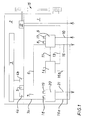
- die schematische Seitenansicht einer erfindungsgemäß ausgestaltete Brennkraftmaschine.
- Die Brennkraftmaschine ist bevorzugt von einer serienmäßig gebauten Dieselbrennkraftmaschine hergeleitet und beispielsweise als Reihen-Brennkraftmaschine mit vier oder sechs Zylindern ausgebildet. Die Brennkraftmaschine weist ein Kurbelgehäuse 1 auf, in dem in bekannter Ausbildung eine Kurbelwelle drehbar gelagert ist, an der in innerhalb des Kurbelgehäuses 1 angeordneten Zylindern bewegbaren Kolben über entsprechende Pleuel angelenkt sind. Das Kurbelgehäuse 1 wird von einem Zylinderkopf 2 abgedeckt, in dem ebenfalls in bekannter Bauart Gaswechseleinrichtungen in Form von Ein- und Auslassventilen angeordnet sind. Die Ein- und Auslassventile sind über entsprechende Einlassleitungen und Auslassleitungen mit an dem Zylinderkopf 2 jeweils befestigten Frischgasleitungen und Abgassammelleitungen verbunden. Weiterhin sind in den Zylinderkopf 2 Kraftstoffeinspritzventile eingesetzt, die von einem elektronischen Steuergerät für die Brennkraftmaschinensteuerung geschaltet werden. Diese Einspritzventile sind über entsprechende Kraftstoffhochdruckleitungen mit einem Kraftstoffhochdruckspeicher 3 verschaltet. Dieser Kraftstoffhochdruckspeicher wird über zwei Hochdruckkraftstoffförderpumpen 4a, 4b mit Kraftstoff befüllt. Um den Kraftstoffdruck in dem Kraftstoffhochdruckspeicher 3 unabhängig von dem durch die Kraftstoffeinspritzventile entnommenen Kraftstoffmengen möglichst konstant zu halten, ist eingangsseitig zu den Hochdruckförderpumpen 4a, 4b eine Kraftstoffzumesseinrichtung 5 vorgesehen, die in Abhängigkeit von dem Kraftstoffdruck in den Kraftstoffhochdruckspeicher 3 die den Hochdruckförderpumpen 4a, 4b zugeführte Kraftstoffmenge steuert. Die Kraftstoffzumesseinrichtung ist dementsprechend über kurze Leitungen mit den Hochdruckförderpumpen 4a, 4b verschaltet und weist einen Einlass auf, der mit einer Kraftstoffzuführleitung 6 verschaltet ist und weiterhin einen Auslass auf, der mit einer Kraftstoffabführleitung 7 verschaltet ist. Von einer über die Kraftstoffzuführleitung 6 weitgehend konstant geförderten Kraftstoffmenge wird entsprechend dem in dem Kraftstoffhochdruckspeicher 3 herrschenden Druck eine bestimmte Menge Kraftstoff über die Kraftstoffabführleitung 7 abgesteuert. Die Hochdruckförderpumpen 4a, 4b sind im Übrigen als Steckpumpen ausgebildet, die direkt in das Kurbelgehäuse 1 der Brennkraftmaschine eingebaut sind. Diese Steckpumpen weisen jeweils einen Pumpenkolben auf, der von einer in dem Kurbelgehäuse 1 der Brennkraftmaschine angeordneten Nockenwelle über entsprechende Nocken betätigt wird. Dabei weist die Nockenwelle bei einer 4-zylindrigen Brennkraftmaschine vorzugsweise jeweils zwei Nocken je Steckpumpe und bei einer 6-zylindrigen Brennkraftmaschine jeweils drei Nocken je Steckpumpe auf. Weiterhin ist die Nockenwelle mit weiteren Gaswechselnocken zur Betätigung der Gaswechselventile versehen. Im Übrigen bilden die zuvor beschriebenen Teile der Kraftstoffeinrichtung die Hochdruckpumpeneinrichtung.
- Über die Kraftstoffzuführleitung 6 wird der Kraftstoffzumesseinrichtung 5 entweder dünnflüssiger Kraftstoff, im Ausführungsbeispiel Diesel, oder dickflüssiger Kraftstoff, im Ausführungsbeispiel Rapsöl, zugeführt. Die entsprechende Umschaltung wird von einem ersten Umschaltventil 8 vorgenommen, das Bestandteil einer ersten Baueinheit 9 ist. Die Baueinheit 9 beinhaltet neben dem Umschaltventil(magneten) 8 den eigentlichen Ventilkörper interne Leitungsverbindungen und gegebenenfalls Rückschlagventile. Dieser ersten Baueinheit 9 und insbesondere dem Ventilkörper des ersten Umschaltventils 8 wird über eine Dieselkraftstoffzuführleitung 10 Dieselkraftstoff zugeführt. In die Dieselkraftstoffzuführleitung 10 ist eine Fördereinrichtung in Form einer elektrischen Förderpumpe sowie eine Filtereinrichtung in Form zumindest eines Dieselkraftstofffilters eingeschaltet. Diese nicht dargestellten Bauteile können als Baugruppe zusammengefasst wahlweise fahrzeug- oder gerätespezifisch an dem Fahrzeug bzw. dem Gerät oder aber an der Brennkraftmaschine, bevorzugt unterhalb der ersten Baueinheit 9, montiert werden.
- Über eine Rapsölzuführleitung 11 wird der ersten Baueinheit 9 und insbesondere dem Ventilkörper des ersten Umschaltventils 8 Rapsöl zugeführt. Das Rapsöl wird von einer mechanisch betriebenen, die Förderanordnung bildenden Kraftstoffpumpe 12 über eine Rapsölleitung 13, zumindest einem die Filteranordnung bildenden Rapsölfilter 14 und weiter über die Rapsölzuführleitung 11 der ersten Baueinheit 9 zugeführt. Die Kraftstoffpumpe 12 ist beispielsweise über einen Riementrieb 15 mit der Kurbelwelle der Brennkraftmaschine verschaltet und fördert folglich bei Betrieb der Brennkraftmaschine kontinuierlich Kraftstoff. Wird die Brennkraftmaschine mit Dieselkraftstoff betrieben, muss das kontinuierlich geförderte Rapsöl aus der ersten Baueinheit 9 über eine Rapsölabführleitung 16 abgesteuert werden. Dieser Absteuervorgang wird von einem vierten Umschaltventil 17 gesteuert oder aber bei entsprechender Ausgestaltung auch von dem ersten Umschaltventil 8. Dies wird später detaillierter erläutert.
- Je nach dem, ob über die Kraftstoffabführleitung 7, 7a, wobei die Kraftstoffabführleitung 7a mit dem Überdruckventil des Kraftstoffhochdruckspeichers 3 und weiterhin dem Leckagesystem der Einspritzventile verschaltet ist, Rapsöl oder Diesel abgesteuert wird, muss dieser Kraftstoff entweder in einen mit Rapsöl befüllten Haupttank oder einen mit Diesel befüllten Zusatztank geleitet werden. Dieser Umschaltvorgang wird von einem zweiten Umschaltventil 18 und einem dritten Umschaltventil 19, die in einer zweiten Baueinheit 20 zusammengefasst sind, gesteuert. Das zweite Umschaltventil 18 und das dritte Umschaltventil 19 können auch zu einem gemeinsam betätigten, beide Schaltfunktionen ausführenden Umschaltventil zusammengefasst sein. Je nach Schaltstellung wird also der über die Kraftstoffabführleitung 7, 7a der zweiten Baueinheit 20 zugeführte Kraftstoff in eine Rapsölabführleitung 16a, die mit einer weiteren mit dem Rapsölfilter 14 verschalteten Rapsölabführleitung 16b und der Rapsölabführleitung 16 verschaltet ist, abgeführt oder in eine Dieselkraftstoffabführleitung 21.
- Wie zuvor erläutert wurde, kann das erste Umschaltventil 8 so geschaltet sein, dass es zwei Eingänge und einen Ausgang hat, wobei an einem Eingang Rapsöl und an dem anderen Eingang Dieselkraftstoff ansteht. Je nach Schaltstellung wird der erste oder der zweite Eingang mit dem Ausgang verschaltet. Bei dieser Ausführung ist - wie beschrieben - das vierte Umschaltventil 17 nötig. Das gleiche erste Umschaltventil 8 kann aber auch so geschaltet sein, dass es einen Eingang und zwei Ausgänge hat. Dem Eingang wird dann Rapsöl zugeführt und entweder mit dem ersten Ausgang, der dann in die Kraftstoffzuführleitung 6 mündet oder mit dem zweiten Ausgang, der dann direkt in die Rapsölabführleitung 16 mündet, verbunden. Bei dieser Ausführung mündet die Dieselzuführleitung 10 über ein in die erste Baueinheit integriertes Rückschlagventil den ersten Ausgang beziehungsweise die weiterführende Kraftstoffzuführleitung 6. In die Rapsölabführleitung 16 kann dann eine Drosseleinrichtung eingesetzt sein, die das Druckniveau auf einem vorgegebenen Wert hält. Bei einem Rapsölbetrieb verhindert das Rückschlagventil, dass Rapsöl bei ausgeschalteter elektrischer Förderpumpe in den Dieseltank gelangen kann.
- Das ganze Kraftstoffsystem ist so ausgebildet, dass es an eine serienmäßig gebaute, als Dieselkraftstoff-Brennkraftmaschine ausgebildete Brennkraftmaschine adaptiert werden kann und dabei die bei der Dieselkraftstoff-Brennkraftmaschine vorhandene Kraftstoffpumpe 12 und der Filter nunmehr als Rapsölfilter 14 weiterverwendet werden können. Im Wesentlichen werden die beschriebenen Umschaltventile in Form einer ersten Baueinheit 9 und einer zweiten Baueinheit 20 an der entsprechenden Brennkraftmaschinenlängsseite zusätzlich angeordnet und - wie beschrieben - verschaltet. Für einen möglichst schnellen Umschaltvorgang von Dieselkraftstoff auf Rapsöl und umgekehrt ist dabei insbesondere die Kraftstoffzuführleitung 6 möglichst kurz ausgebildet.
- 1
- Kurbelgehäuse
- 2
- Zylinderkopf
- 3
- Kraftstoffhochdruckspeicher
- 4a, 4b
- Hochdruckförderpumpe
- 5
- Kraftstoffzumesseinrichtung
- 6
- Kraftstoffzuführleitung
- 7, 7a
- Kraftstoffabführleitung
- 8
- erstes Umschaltventil
- 9
- erste Baueinheit
- 10
- Dieselkraftstoffzuführleitung
- 11
- Rapsölzuführleitung
- 12
- Kraftstoffpumpe
- 13
- Rapsölleitung
- 14
- Rapsölfilter
- 15
- Riementrieb
- 16, 16a, 16b
- Rapsölabführleitung
- 17
- viertes Umschaltventil
- 18
- zweites Umschaltventil
- 19
- drittes Umschaltventil
- 20
- zweite Baueinheit
- 21
- Dieselkraftstoffabführleitung
Claims (9)
- Brennkraftmaschine, insbesondere selbstzündende Brennkraftmaschine, die wechselweise mit einem dünnflüssigen Kraftstoff, insbesondere Diesel, und einem dickflüssigen Kraftstoff, insbesondere Rapsöl, betrieben wird, wobei ein den dünnflüssigen Kraftstoff aufnehmender Zusatztank über eine Filtereinrichtung und eine Fördereinrichtung sowie ein den dickflüssigen Kraftstoff aufnehmender Haupttank über eine Filteranordnung und eine Förderanordnung über Zuführungen mit einer gemeinsamen Hochdruckpumpeneinrichtung verschaltet sind und ein Niederdruckausgang der Hochdruckpumpeneinrichtung über ein Rücklaufleitungssystem schaltbar mit dem Haupttank und dem Zusatztank verbunden ist,
dadurch gekennzeichnet, dass die Filteranordnung und Förderanordnung zusammen mit der Hochdruckpumpeneinrichtung im Bereich einer Längsseite der Brennkraftmaschine angeordnet sind. - Brennkraftmaschine nach Anspruch 1,
dadurch gekennzeichnet, dass ein erstes Umschaltventil (8) zur wechselweisen Zuführung von dünnflüssigem Kraftstoff und dickflüssigem Kraftstoff zu der Hochdruckpumpeneinrichtung und ein zweites Umschaltventil (18) und ein drittes Umschaltventil (19) oder ein zusammengefasstes zweites und drittes Umschaltventil zur wechselweisen Rückführung von aus der Hochdruckpumpeneinrichtung abgesteuertem dünnflüssigen Kraftstoff und/oder dickflüssigem Kraftstoff in den Zusatztank oder den Haupttank vorhanden sind und dass die Umschaltventile ebenfalls auf der Längsseite der Brennkraftmaschine angeordnet sind. - Brennkraftmaschine nach einem der vorherigen Ansprüche,
dadurch gekennzeichnet, dass ein viertes Umschaltventil (17) in eine Rückführleitung (16) zur Rückführung von dickflüssigem Kraftstoff ausgangsseitig der Filteranordnung in den Haupttank auf der Längsseite angeordnet ist. - Brennkraftmaschine nach einem der vorherigen Ansprüche,
dadurch gekennzeichnet, dass das zumindest das erste Umschaltventil (8) eine erste Baueinheit (9) bildet und das zweite Umschaltventil (18) und das dritte Umschaltventil (19) oder ein zusammengefasstes zweites und drittes Umschaltventil eine zweite Baueinheit (20) bilden. - Brennkraftmaschine nach Anspruch 4
dadurch gekennzeichnet, dass die erste Baueinheit (9) und die zweite Baueinheit (20) fest an der Brennkraftmaschine montiert sind. - Brennkraftmaschine nach einem der vorherigen Ansprüche,
dadurch gekennzeichnet, dass die Filtereinrichtung und die Fördereinrichtung zu einer Baugruppe zusammengefasst sind. - Brennkraftmaschine nach Anspruch 6,
dadurch gekennzeichnet, dass die Baugruppe auf einer Konsolenplatte befestigt ist, die seitlich unterhalb der Filteranordnung angebracht ist. - Brennkraftmaschine nach Anspruch 6
dadurch gekennzeichnet, dass die Baugruppe fahrzeug- oder gerätespezifisch einbaubar ist. - Brennkraftmaschine nach einem der vorherigen Ansprüche
dadurch gekennzeichnet, dass ein Wärmetauscher und eine Vorfiltereinrichtung für den dickflüssigen Kraftstoff fahrzeug- oder gerätespezifisch einbaubar sind.
Applications Claiming Priority (1)
| Application Number | Priority Date | Filing Date | Title |
|---|---|---|---|
| DE102007031779A DE102007031779A1 (de) | 2007-07-07 | 2007-07-07 | Rapsölmotor |
Publications (2)
| Publication Number | Publication Date |
|---|---|
| EP2014907A1 true EP2014907A1 (de) | 2009-01-14 |
| EP2014907B1 EP2014907B1 (de) | 2012-09-12 |
Family
ID=39864789
Family Applications (1)
| Application Number | Title | Priority Date | Filing Date |
|---|---|---|---|
| EP20080010661 Not-in-force EP2014907B1 (de) | 2007-07-07 | 2008-06-12 | Rapsölmotor |
Country Status (3)
| Country | Link |
|---|---|
| EP (1) | EP2014907B1 (de) |
| DE (1) | DE102007031779A1 (de) |
| ES (1) | ES2396382T3 (de) |
Families Citing this family (2)
| Publication number | Priority date | Publication date | Assignee | Title |
|---|---|---|---|---|
| CN116291995B (zh) * | 2023-03-06 | 2025-08-01 | 一汽解放青岛汽车有限公司 | 燃油供给系统及车辆 |
| CN116220976B (zh) * | 2023-03-06 | 2025-08-01 | 一汽解放青岛汽车有限公司 | 燃油供给系统及车辆 |
Citations (11)
| Publication number | Priority date | Publication date | Assignee | Title |
|---|---|---|---|---|
| GB625400A (en) * | 1946-11-08 | 1949-06-27 | Ford Motor Co | Improvements in or relating to the driving of the lubricant pumps the ignition distributors and the liquid fuel pumps of internal combustion engines |
| US2877713A (en) * | 1957-08-09 | 1959-03-17 | Rubie F Morgan | Fuel pump |
| US4620568A (en) * | 1985-10-09 | 1986-11-04 | Sumerford Harold A | Vehicle off road fuel use indicator |
| DE3800585A1 (de) | 1987-01-13 | 1988-07-28 | Kloeckner Humboldt Deutz Ag | Vorrichtung zum alternativen betreiben einer dieselbrennkraftmaschine mit dieseloel und rapsoel |
| US5007806A (en) * | 1989-03-30 | 1991-04-16 | Mallory, Inc. | Fuel pump |
| DE4418856A1 (de) * | 1994-05-30 | 1995-12-07 | Robur Werke Gmbh I L | Verfahren und Einrichtung zum Einsatz von Pflanzenölkraftstoff und/oder verflüssigtem Fett in herkömmlichen Dieselmotoren |
| DE202005008142U1 (de) * | 2005-05-24 | 2005-07-28 | Blon, Thomas | Anordnung zur Nutzung alternativer Treibstoffe in konventionellen selbstzündenden Verbrennungsmotoren |
| WO2006005930A2 (en) * | 2004-07-08 | 2006-01-19 | Regenatec Limited | Operating internal combustion engines with plant oil |
| DE202006009290U1 (de) * | 2006-06-10 | 2006-10-26 | Burmester, Hans-Joachim, Dipl.-Ing. | Steuerblock für den Betrieb eines Dieselmotors mit Pflanzenöl |
| DE202006014975U1 (de) * | 2005-11-04 | 2006-12-07 | Sellentin, Alexander | Kraftstoffzuführungseinrichtung für einen Dieselmotor |
| JP2007120423A (ja) * | 2005-10-28 | 2007-05-17 | Isuzu Motors Ltd | 低沸点燃料用の燃料供給装置 |
Family Cites Families (4)
| Publication number | Priority date | Publication date | Assignee | Title |
|---|---|---|---|---|
| DE19635220A1 (de) * | 1996-08-30 | 1998-05-14 | Georg Lohmann | Steuerungseinheit für Dieselmotoren, die mit Fetten und Ölen von Pflanze und Tier betrieben werden |
| DE102004050601B4 (de) * | 2004-10-15 | 2006-12-21 | Kangler, Wolfram, Dipl.-Phys. | Wärmetauschmodul |
| DE202005007712U1 (de) * | 2005-05-11 | 2006-09-21 | Storimpex Im- & Export Gmbh | Pflanzenölbetrieb von Dieselmotoren mit Spülung |
| DE102006000621A1 (de) * | 2005-10-28 | 2007-05-03 | Rainer Dirnhofer | Raps-/Dieselventil |
-
2007
- 2007-07-07 DE DE102007031779A patent/DE102007031779A1/de not_active Withdrawn
-
2008
- 2008-06-12 EP EP20080010661 patent/EP2014907B1/de not_active Not-in-force
- 2008-06-12 ES ES08010661T patent/ES2396382T3/es active Active
Patent Citations (11)
| Publication number | Priority date | Publication date | Assignee | Title |
|---|---|---|---|---|
| GB625400A (en) * | 1946-11-08 | 1949-06-27 | Ford Motor Co | Improvements in or relating to the driving of the lubricant pumps the ignition distributors and the liquid fuel pumps of internal combustion engines |
| US2877713A (en) * | 1957-08-09 | 1959-03-17 | Rubie F Morgan | Fuel pump |
| US4620568A (en) * | 1985-10-09 | 1986-11-04 | Sumerford Harold A | Vehicle off road fuel use indicator |
| DE3800585A1 (de) | 1987-01-13 | 1988-07-28 | Kloeckner Humboldt Deutz Ag | Vorrichtung zum alternativen betreiben einer dieselbrennkraftmaschine mit dieseloel und rapsoel |
| US5007806A (en) * | 1989-03-30 | 1991-04-16 | Mallory, Inc. | Fuel pump |
| DE4418856A1 (de) * | 1994-05-30 | 1995-12-07 | Robur Werke Gmbh I L | Verfahren und Einrichtung zum Einsatz von Pflanzenölkraftstoff und/oder verflüssigtem Fett in herkömmlichen Dieselmotoren |
| WO2006005930A2 (en) * | 2004-07-08 | 2006-01-19 | Regenatec Limited | Operating internal combustion engines with plant oil |
| DE202005008142U1 (de) * | 2005-05-24 | 2005-07-28 | Blon, Thomas | Anordnung zur Nutzung alternativer Treibstoffe in konventionellen selbstzündenden Verbrennungsmotoren |
| JP2007120423A (ja) * | 2005-10-28 | 2007-05-17 | Isuzu Motors Ltd | 低沸点燃料用の燃料供給装置 |
| DE202006014975U1 (de) * | 2005-11-04 | 2006-12-07 | Sellentin, Alexander | Kraftstoffzuführungseinrichtung für einen Dieselmotor |
| DE202006009290U1 (de) * | 2006-06-10 | 2006-10-26 | Burmester, Hans-Joachim, Dipl.-Ing. | Steuerblock für den Betrieb eines Dieselmotors mit Pflanzenöl |
Also Published As
| Publication number | Publication date |
|---|---|
| DE102007031779A1 (de) | 2009-01-08 |
| ES2396382T3 (es) | 2013-02-21 |
| EP2014907B1 (de) | 2012-09-12 |
Similar Documents
| Publication | Publication Date | Title |
|---|---|---|
| EP2789839B1 (de) | System und Verfahren zur Wassereinspritzung für eine Brennkraftmaschine | |
| EP2035683B1 (de) | Dieselmotorisch betriebene brennkraftmaschine | |
| DE102004009792B3 (de) | Kraftstoffzuführeinrichtung zur Versorgung der Injektoren an Brennräumen einer Brennkraftmaschine mit Kraftstoff | |
| EP1296060B1 (de) | Kraftstoffeinspritzeinrichtung für eine Brennkraftmaschine | |
| DE102008001240A1 (de) | Verfahren und Vorrichtung zur Steuerung eines Kraftstoffversorgungssystems | |
| DE19609800C1 (de) | Brennstoffeinspritzsystem für Emulsionsbetrieb | |
| DE102013213506A1 (de) | Verfahren zum Betreiben eines Kraftstoffeinspritzsystems mit einer Kraftstofffilterheizung und Kraftstoffeinspritzsystem | |
| EP2601396B1 (de) | Verbrennungskraftmaschine mit flüssigen und gasförmigen kraftstoff | |
| DE102004050601B4 (de) | Wärmetauschmodul | |
| WO2020064495A1 (de) | Wassereinspritzsystem sowie verfahren zum betreiben eines wassereinspritzsystems | |
| EP2014907B1 (de) | Rapsölmotor | |
| DE102009055037B4 (de) | Common Rail Minimaldruck zum schnellen Druckaufbau | |
| EP3685033B1 (de) | Kraftfahrzeug mit wassereinspritzvorrichtung für eine brennkraftmaschine | |
| DE102009028739A1 (de) | Schnellstart eines Common Rail-Systems | |
| EP2014908B1 (de) | Wechselweise mit Dieselkraftstoff oder einem biogenen Kraftstoff betreibbare Brennkraftmaschine | |
| DE102008042604A1 (de) | Kraftstoff-Einspritzsystem und Verfahren zum Betreiben einer Brennkraftmaschine | |
| DE10131630A1 (de) | Kraftstoffanlage für ein mit Pflanzenöl zu betreibendes Dieselantriebsaggregat | |
| DE102012200764B3 (de) | Common-Rail-Einspritzsystem für einen Verbrennungsmotor | |
| DE10315318A1 (de) | Verfahren zum Betreiben einer Brennkraftmaschine | |
| DE10001829A1 (de) | Bedarfsgesteuertes Regelungsverfahren von Kraftstoffförderpumpen bei Mehrpumpensystemen | |
| DE102018200091A1 (de) | Wassereinspritzvorrichtung für eine Brennkraftmaschine und Verfahren zur Wassereinspritzung | |
| DE19530261A1 (de) | Niederdruck-Kraftstoffördersystem mit Hochdruckspeicherung | |
| EP3581783A1 (de) | Wassereinspritzvorrichtung für eine brennkraftmaschine und verfahren zur wassereinspritzung | |
| DE102009061750B3 (de) | Schnellstart eines Common Rail-Systems | |
| DE102018218749A1 (de) | Wassereinspritzvorrichtung für eine Brennkraftmaschine |
Legal Events
| Date | Code | Title | Description |
|---|---|---|---|
| PUAI | Public reference made under article 153(3) epc to a published international application that has entered the european phase |
Free format text: ORIGINAL CODE: 0009012 |
|
| AK | Designated contracting states |
Kind code of ref document: A1 Designated state(s): AT BE BG CH CY CZ DE DK EE ES FI FR GB GR HR HU IE IS IT LI LT LU LV MC MT NL NO PL PT RO SE SI SK TR |
|
| AX | Request for extension of the european patent |
Extension state: AL BA MK RS |
|
| 17P | Request for examination filed |
Effective date: 20090703 |
|
| 17Q | First examination report despatched |
Effective date: 20090810 |
|
| AKX | Designation fees paid |
Designated state(s): AT BE BG CH CY CZ DE DK EE ES FI FR GB GR HR HU IE IS IT LI LT LU LV MC MT NL NO PL PT RO SE SI SK TR |
|
| GRAP | Despatch of communication of intention to grant a patent |
Free format text: ORIGINAL CODE: EPIDOSNIGR1 |
|
| GRAS | Grant fee paid |
Free format text: ORIGINAL CODE: EPIDOSNIGR3 |
|
| GRAA | (expected) grant |
Free format text: ORIGINAL CODE: 0009210 |
|
| AK | Designated contracting states |
Kind code of ref document: B1 Designated state(s): AT BE BG CH CY CZ DE DK EE ES FI FR GB GR HR HU IE IS IT LI LT LU LV MC MT NL NO PL PT RO SE SI SK TR |
|
| REG | Reference to a national code |
Ref country code: GB Ref legal event code: FG4D Free format text: NOT ENGLISH |
|
| REG | Reference to a national code |
Ref country code: CH Ref legal event code: EP |
|
| REG | Reference to a national code |
Ref country code: AT Ref legal event code: REF Ref document number: 575214 Country of ref document: AT Kind code of ref document: T Effective date: 20120915 |
|
| REG | Reference to a national code |
Ref country code: IE Ref legal event code: FG4D Free format text: LANGUAGE OF EP DOCUMENT: GERMAN |
|
| REG | Reference to a national code |
Ref country code: DE Ref legal event code: R096 Ref document number: 502008008129 Country of ref document: DE Effective date: 20121108 |
|
| REG | Reference to a national code |
Ref country code: NL Ref legal event code: T3 |
|
| PG25 | Lapsed in a contracting state [announced via postgrant information from national office to epo] |
Ref country code: CY Free format text: LAPSE BECAUSE OF FAILURE TO SUBMIT A TRANSLATION OF THE DESCRIPTION OR TO PAY THE FEE WITHIN THE PRESCRIBED TIME-LIMIT Effective date: 20120912 Ref country code: FI Free format text: LAPSE BECAUSE OF FAILURE TO SUBMIT A TRANSLATION OF THE DESCRIPTION OR TO PAY THE FEE WITHIN THE PRESCRIBED TIME-LIMIT Effective date: 20120912 Ref country code: LT Free format text: LAPSE BECAUSE OF FAILURE TO SUBMIT A TRANSLATION OF THE DESCRIPTION OR TO PAY THE FEE WITHIN THE PRESCRIBED TIME-LIMIT Effective date: 20120912 Ref country code: HR Free format text: LAPSE BECAUSE OF FAILURE TO SUBMIT A TRANSLATION OF THE DESCRIPTION OR TO PAY THE FEE WITHIN THE PRESCRIBED TIME-LIMIT Effective date: 20120912 Ref country code: NO Free format text: LAPSE BECAUSE OF FAILURE TO SUBMIT A TRANSLATION OF THE DESCRIPTION OR TO PAY THE FEE WITHIN THE PRESCRIBED TIME-LIMIT Effective date: 20121212 |
|
| REG | Reference to a national code |
Ref country code: ES Ref legal event code: FG2A Ref document number: 2396382 Country of ref document: ES Kind code of ref document: T3 Effective date: 20130221 |
|
| REG | Reference to a national code |
Ref country code: LT Ref legal event code: MG4D Effective date: 20120912 |
|
| PG25 | Lapsed in a contracting state [announced via postgrant information from national office to epo] |
Ref country code: SE Free format text: LAPSE BECAUSE OF FAILURE TO SUBMIT A TRANSLATION OF THE DESCRIPTION OR TO PAY THE FEE WITHIN THE PRESCRIBED TIME-LIMIT Effective date: 20120912 Ref country code: GR Free format text: LAPSE BECAUSE OF FAILURE TO SUBMIT A TRANSLATION OF THE DESCRIPTION OR TO PAY THE FEE WITHIN THE PRESCRIBED TIME-LIMIT Effective date: 20121213 Ref country code: SI Free format text: LAPSE BECAUSE OF FAILURE TO SUBMIT A TRANSLATION OF THE DESCRIPTION OR TO PAY THE FEE WITHIN THE PRESCRIBED TIME-LIMIT Effective date: 20120912 Ref country code: LV Free format text: LAPSE BECAUSE OF FAILURE TO SUBMIT A TRANSLATION OF THE DESCRIPTION OR TO PAY THE FEE WITHIN THE PRESCRIBED TIME-LIMIT Effective date: 20120912 |
|
| PG25 | Lapsed in a contracting state [announced via postgrant information from national office to epo] |
Ref country code: RO Free format text: LAPSE BECAUSE OF FAILURE TO SUBMIT A TRANSLATION OF THE DESCRIPTION OR TO PAY THE FEE WITHIN THE PRESCRIBED TIME-LIMIT Effective date: 20120912 Ref country code: EE Free format text: LAPSE BECAUSE OF FAILURE TO SUBMIT A TRANSLATION OF THE DESCRIPTION OR TO PAY THE FEE WITHIN THE PRESCRIBED TIME-LIMIT Effective date: 20120912 Ref country code: IS Free format text: LAPSE BECAUSE OF FAILURE TO SUBMIT A TRANSLATION OF THE DESCRIPTION OR TO PAY THE FEE WITHIN THE PRESCRIBED TIME-LIMIT Effective date: 20130112 Ref country code: CZ Free format text: LAPSE BECAUSE OF FAILURE TO SUBMIT A TRANSLATION OF THE DESCRIPTION OR TO PAY THE FEE WITHIN THE PRESCRIBED TIME-LIMIT Effective date: 20120912 |
|
| PG25 | Lapsed in a contracting state [announced via postgrant information from national office to epo] |
Ref country code: PT Free format text: LAPSE BECAUSE OF FAILURE TO SUBMIT A TRANSLATION OF THE DESCRIPTION OR TO PAY THE FEE WITHIN THE PRESCRIBED TIME-LIMIT Effective date: 20130114 Ref country code: SK Free format text: LAPSE BECAUSE OF FAILURE TO SUBMIT A TRANSLATION OF THE DESCRIPTION OR TO PAY THE FEE WITHIN THE PRESCRIBED TIME-LIMIT Effective date: 20120912 Ref country code: PL Free format text: LAPSE BECAUSE OF FAILURE TO SUBMIT A TRANSLATION OF THE DESCRIPTION OR TO PAY THE FEE WITHIN THE PRESCRIBED TIME-LIMIT Effective date: 20120912 |
|
| PLBE | No opposition filed within time limit |
Free format text: ORIGINAL CODE: 0009261 |
|
| STAA | Information on the status of an ep patent application or granted ep patent |
Free format text: STATUS: NO OPPOSITION FILED WITHIN TIME LIMIT |
|
| PG25 | Lapsed in a contracting state [announced via postgrant information from national office to epo] |
Ref country code: DK Free format text: LAPSE BECAUSE OF FAILURE TO SUBMIT A TRANSLATION OF THE DESCRIPTION OR TO PAY THE FEE WITHIN THE PRESCRIBED TIME-LIMIT Effective date: 20120912 Ref country code: BG Free format text: LAPSE BECAUSE OF FAILURE TO SUBMIT A TRANSLATION OF THE DESCRIPTION OR TO PAY THE FEE WITHIN THE PRESCRIBED TIME-LIMIT Effective date: 20121212 |
|
| 26N | No opposition filed |
Effective date: 20130613 |
|
| REG | Reference to a national code |
Ref country code: DE Ref legal event code: R097 Ref document number: 502008008129 Country of ref document: DE Effective date: 20130613 |
|
| BERE | Be: lapsed |
Owner name: DEUTZ A.G. Effective date: 20130630 |
|
| PG25 | Lapsed in a contracting state [announced via postgrant information from national office to epo] |
Ref country code: MC Free format text: LAPSE BECAUSE OF FAILURE TO SUBMIT A TRANSLATION OF THE DESCRIPTION OR TO PAY THE FEE WITHIN THE PRESCRIBED TIME-LIMIT Effective date: 20120912 |
|
| REG | Reference to a national code |
Ref country code: CH Ref legal event code: PL |
|
| REG | Reference to a national code |
Ref country code: IE Ref legal event code: MM4A |
|
| PG25 | Lapsed in a contracting state [announced via postgrant information from national office to epo] |
Ref country code: BE Free format text: LAPSE BECAUSE OF NON-PAYMENT OF DUE FEES Effective date: 20130630 |
|
| PG25 | Lapsed in a contracting state [announced via postgrant information from national office to epo] |
Ref country code: IE Free format text: LAPSE BECAUSE OF NON-PAYMENT OF DUE FEES Effective date: 20130612 Ref country code: LI Free format text: LAPSE BECAUSE OF NON-PAYMENT OF DUE FEES Effective date: 20130630 Ref country code: CH Free format text: LAPSE BECAUSE OF NON-PAYMENT OF DUE FEES Effective date: 20130630 |
|
| PG25 | Lapsed in a contracting state [announced via postgrant information from national office to epo] |
Ref country code: MT Free format text: LAPSE BECAUSE OF FAILURE TO SUBMIT A TRANSLATION OF THE DESCRIPTION OR TO PAY THE FEE WITHIN THE PRESCRIBED TIME-LIMIT Effective date: 20120912 |
|
| REG | Reference to a national code |
Ref country code: FR Ref legal event code: PLFP Year of fee payment: 8 |
|
| PG25 | Lapsed in a contracting state [announced via postgrant information from national office to epo] |
Ref country code: TR Free format text: LAPSE BECAUSE OF FAILURE TO SUBMIT A TRANSLATION OF THE DESCRIPTION OR TO PAY THE FEE WITHIN THE PRESCRIBED TIME-LIMIT Effective date: 20120912 |
|
| PG25 | Lapsed in a contracting state [announced via postgrant information from national office to epo] |
Ref country code: LU Free format text: LAPSE BECAUSE OF NON-PAYMENT OF DUE FEES Effective date: 20130612 Ref country code: HU Free format text: LAPSE BECAUSE OF FAILURE TO SUBMIT A TRANSLATION OF THE DESCRIPTION OR TO PAY THE FEE WITHIN THE PRESCRIBED TIME-LIMIT; INVALID AB INITIO Effective date: 20080612 |
|
| PGFP | Annual fee paid to national office [announced via postgrant information from national office to epo] |
Ref country code: GB Payment date: 20150618 Year of fee payment: 8 Ref country code: ES Payment date: 20150626 Year of fee payment: 8 |
|
| PGFP | Annual fee paid to national office [announced via postgrant information from national office to epo] |
Ref country code: IT Payment date: 20150623 Year of fee payment: 8 Ref country code: AT Payment date: 20150619 Year of fee payment: 8 Ref country code: FR Payment date: 20150619 Year of fee payment: 8 Ref country code: NL Payment date: 20150618 Year of fee payment: 8 |
|
| PGFP | Annual fee paid to national office [announced via postgrant information from national office to epo] |
Ref country code: DE Payment date: 20160629 Year of fee payment: 9 |
|
| REG | Reference to a national code |
Ref country code: NL Ref legal event code: MM Effective date: 20160701 |
|
| REG | Reference to a national code |
Ref country code: AT Ref legal event code: MM01 Ref document number: 575214 Country of ref document: AT Kind code of ref document: T Effective date: 20160612 |
|
| GBPC | Gb: european patent ceased through non-payment of renewal fee |
Effective date: 20160612 |
|
| REG | Reference to a national code |
Ref country code: FR Ref legal event code: ST Effective date: 20170228 |
|
| PG25 | Lapsed in a contracting state [announced via postgrant information from national office to epo] |
Ref country code: FR Free format text: LAPSE BECAUSE OF NON-PAYMENT OF DUE FEES Effective date: 20160630 |
|
| PG25 | Lapsed in a contracting state [announced via postgrant information from national office to epo] |
Ref country code: GB Free format text: LAPSE BECAUSE OF NON-PAYMENT OF DUE FEES Effective date: 20160612 Ref country code: AT Free format text: LAPSE BECAUSE OF NON-PAYMENT OF DUE FEES Effective date: 20160612 Ref country code: NL Free format text: LAPSE BECAUSE OF NON-PAYMENT OF DUE FEES Effective date: 20160701 |
|
| PG25 | Lapsed in a contracting state [announced via postgrant information from national office to epo] |
Ref country code: IT Free format text: LAPSE BECAUSE OF NON-PAYMENT OF DUE FEES Effective date: 20160612 |
|
| REG | Reference to a national code |
Ref country code: DE Ref legal event code: R119 Ref document number: 502008008129 Country of ref document: DE |
|
| PG25 | Lapsed in a contracting state [announced via postgrant information from national office to epo] |
Ref country code: DE Free format text: LAPSE BECAUSE OF NON-PAYMENT OF DUE FEES Effective date: 20180103 |
|
| PG25 | Lapsed in a contracting state [announced via postgrant information from national office to epo] |
Ref country code: ES Free format text: LAPSE BECAUSE OF NON-PAYMENT OF DUE FEES Effective date: 20160613 |
|
| REG | Reference to a national code |
Ref country code: ES Ref legal event code: FD2A Effective date: 20181203 |