EP2014919A2 - Soupape de réglage pour le réglage du volume d'alimentation d'une pompe volumétrique - Google Patents
Soupape de réglage pour le réglage du volume d'alimentation d'une pompe volumétrique Download PDFInfo
- Publication number
- EP2014919A2 EP2014919A2 EP20080159994 EP08159994A EP2014919A2 EP 2014919 A2 EP2014919 A2 EP 2014919A2 EP 20080159994 EP20080159994 EP 20080159994 EP 08159994 A EP08159994 A EP 08159994A EP 2014919 A2 EP2014919 A2 EP 2014919A2
- Authority
- EP
- European Patent Office
- Prior art keywords
- valve
- pump
- fluid
- piston
- adjustment
- Prior art date
- Legal status (The legal status is an assumption and is not a legal conclusion. Google has not performed a legal analysis and makes no representation as to the accuracy of the status listed.)
- Granted
Links
Images


Classifications
-
- F—MECHANICAL ENGINEERING; LIGHTING; HEATING; WEAPONS; BLASTING
- F04—POSITIVE - DISPLACEMENT MACHINES FOR LIQUIDS; PUMPS FOR LIQUIDS OR ELASTIC FLUIDS
- F04C—ROTARY-PISTON, OR OSCILLATING-PISTON, POSITIVE-DISPLACEMENT MACHINES FOR LIQUIDS; ROTARY-PISTON, OR OSCILLATING-PISTON, POSITIVE-DISPLACEMENT PUMPS
- F04C14/00—Control of, monitoring of, or safety arrangements for, machines, pumps or pumping installations
- F04C14/18—Control of, monitoring of, or safety arrangements for, machines, pumps or pumping installations characterised by varying the volume of the working chamber
- F04C14/185—Control of, monitoring of, or safety arrangements for, machines, pumps or pumping installations characterised by varying the volume of the working chamber by varying the useful pumping length of the cooperating members in the axial direction
-
- F—MECHANICAL ENGINEERING; LIGHTING; HEATING; WEAPONS; BLASTING
- F04—POSITIVE - DISPLACEMENT MACHINES FOR LIQUIDS; PUMPS FOR LIQUIDS OR ELASTIC FLUIDS
- F04C—ROTARY-PISTON, OR OSCILLATING-PISTON, POSITIVE-DISPLACEMENT MACHINES FOR LIQUIDS; ROTARY-PISTON, OR OSCILLATING-PISTON, POSITIVE-DISPLACEMENT PUMPS
- F04C14/00—Control of, monitoring of, or safety arrangements for, machines, pumps or pumping installations
- F04C14/18—Control of, monitoring of, or safety arrangements for, machines, pumps or pumping installations characterised by varying the volume of the working chamber
- F04C14/22—Control of, monitoring of, or safety arrangements for, machines, pumps or pumping installations characterised by varying the volume of the working chamber by changing the eccentricity between cooperating members
- F04C14/223—Control of, monitoring of, or safety arrangements for, machines, pumps or pumping installations characterised by varying the volume of the working chamber by changing the eccentricity between cooperating members using a movable cam
-
- F—MECHANICAL ENGINEERING; LIGHTING; HEATING; WEAPONS; BLASTING
- F04—POSITIVE - DISPLACEMENT MACHINES FOR LIQUIDS; PUMPS FOR LIQUIDS OR ELASTIC FLUIDS
- F04C—ROTARY-PISTON, OR OSCILLATING-PISTON, POSITIVE-DISPLACEMENT MACHINES FOR LIQUIDS; ROTARY-PISTON, OR OSCILLATING-PISTON, POSITIVE-DISPLACEMENT PUMPS
- F04C2210/00—Fluid
- F04C2210/14—Lubricant
-
- F—MECHANICAL ENGINEERING; LIGHTING; HEATING; WEAPONS; BLASTING
- F04—POSITIVE - DISPLACEMENT MACHINES FOR LIQUIDS; PUMPS FOR LIQUIDS OR ELASTIC FLUIDS
- F04C—ROTARY-PISTON, OR OSCILLATING-PISTON, POSITIVE-DISPLACEMENT MACHINES FOR LIQUIDS; ROTARY-PISTON, OR OSCILLATING-PISTON, POSITIVE-DISPLACEMENT PUMPS
- F04C2270/00—Control; Monitoring or safety arrangements
- F04C2270/18—Pressure
-
- F—MECHANICAL ENGINEERING; LIGHTING; HEATING; WEAPONS; BLASTING
- F04—POSITIVE - DISPLACEMENT MACHINES FOR LIQUIDS; PUMPS FOR LIQUIDS OR ELASTIC FLUIDS
- F04C—ROTARY-PISTON, OR OSCILLATING-PISTON, POSITIVE-DISPLACEMENT MACHINES FOR LIQUIDS; ROTARY-PISTON, OR OSCILLATING-PISTON, POSITIVE-DISPLACEMENT PUMPS
- F04C2270/00—Control; Monitoring or safety arrangements
- F04C2270/20—Flow
-
- Y—GENERAL TAGGING OF NEW TECHNOLOGICAL DEVELOPMENTS; GENERAL TAGGING OF CROSS-SECTIONAL TECHNOLOGIES SPANNING OVER SEVERAL SECTIONS OF THE IPC; TECHNICAL SUBJECTS COVERED BY FORMER USPC CROSS-REFERENCE ART COLLECTIONS [XRACs] AND DIGESTS
- Y10—TECHNICAL SUBJECTS COVERED BY FORMER USPC
- Y10T—TECHNICAL SUBJECTS COVERED BY FORMER US CLASSIFICATION
- Y10T137/00—Fluid handling
- Y10T137/8593—Systems
- Y10T137/86493—Multi-way valve unit
- Y10T137/86574—Supply and exhaust
- Y10T137/86622—Motor-operated
-
- Y—GENERAL TAGGING OF NEW TECHNOLOGICAL DEVELOPMENTS; GENERAL TAGGING OF CROSS-SECTIONAL TECHNOLOGIES SPANNING OVER SEVERAL SECTIONS OF THE IPC; TECHNICAL SUBJECTS COVERED BY FORMER USPC CROSS-REFERENCE ART COLLECTIONS [XRACs] AND DIGESTS
- Y10—TECHNICAL SUBJECTS COVERED BY FORMER USPC
- Y10T—TECHNICAL SUBJECTS COVERED BY FORMER US CLASSIFICATION
- Y10T137/00—Fluid handling
- Y10T137/8593—Systems
- Y10T137/86493—Multi-way valve unit
- Y10T137/86574—Supply and exhaust
- Y10T137/8667—Reciprocating valve
- Y10T137/86694—Piston valve
- Y10T137/86702—With internal flow passage
Definitions
- the invention relates to an adjustment valve for the adjustment of the delivery volume of a positive displacement pump and a positive displacement pump with the adjustment valve, which is arranged for the adjustment of the delivery volume of a fluid to be delivered by the pump in a fluid circuit of the pump.
- the invention accordingly also relates to the adjustment valve as such, as far as it is provided for the adjustment of the delivery volume of a positive displacement pump.
- Positive displacement pumps deliver fluids at a volume flow proportional to the pump speed.
- the delivery volume per revolution or reciprocating stroke, the so-called specific volume flow is constant or, in practice, can be regarded as constant, at least to a good approximation.
- the constancy per revolution or stroke and, accordingly, the proportionality to the pump speed is troublesome, for example, in applications in which the unit to be supplied by the respective pump has a fluid requirement which is lower in one or more speed range (s) of the pump than that from the Proportionality resulting volumetric flow. Accordingly, in the respective speed range, the pump delivers a volume flow above the demand, which is dissipated with loss.
- the problem is in the US 6 126 420 B already disclosed an internal gear pump with adjustable delivery volume to solve the problem,
- the US Pat. No. 6,244,839 B1 apparently also an internal gear pump with adjustable displacement.
- the inner gear is axially displaceable relative to the outer gear.
- the inner gear is part of an axially displaceable adjusting unit, which is formed as a double-acting piston.
- the adjusting unit is acted upon by a 4/3-way adjusting valve with the pumped by the pump fluid, Das
- the adjusting valve has a valve housing and a valve piston axially reciprocating valve piston which is acted upon at one axial end with the funded fluid and at the other axial end with a pressure of the fluid counteracting force of a valve spring.
- the position of the valve piston adjusts according to the balance of the force of the valve spring and the force generated by the fluid pressure.
- the adjustment valve is designed so that the adjustment of the pump moves when reaching a predetermined by the valve spring fluid pressure from an axial position for maximum delivery volume toward an axial position for minimum delivery.
- the preload force of the valve spring is adjusted at the adjustment valve
- a positive displacement pump with an adjusting valve is known, the movable valve piston for adjusting the delivery volume of the pump in an axial direction with fluid of the high pressure side of the pump and the fluid counteracting acted upon by a spring force.
- a control device is provided for the adjusting valve, which exerts an additional force on the valve piston.
- an electric stepper motor for the adjustment of the biasing force of the valve spring and a magnetic coil for generating an additional magnetic force banned by the adjustment valve fluid flow acts on a displacement unit of the pump only in the direction of maximum delivery volume, while in the opposite direction always the pressure of the High pressure side acts.
- the invention is based on a positive displacement pump for the supply of an aggregate with fluid, which has a pump housing with a delivery chamber and a delivery member movable in the delivery member, which acts directly on the fluid to demand this through the delivery chamber.
- the delivery member may, upon execution of a conveying movement, the fluid alone or in cooperation with one or possibly several further delivery member (s) of an inlet of the delivery chamber while increasing the pressure
- the pump is preferably arranged in a closed fluid circuit, but in principle can also serve to convey the fluid in an open fluid circuit.
- the pump is preferably arranged in a closed fluid circuit.
- the pump When integrated in a closed fluid circuit, it draws the fluid on the low-pressure side from a reservoir through the inlet into the delivery chamber and conveys it on the high pressure side to the or possibly several to be supplied with the fluid unit (s). Downstream of the aggregate (s), the fluid returns to the reservoir, closing the fluid circuit.
- the pump can be used for example for the supply of a hydraulic press with pressurized fluid.
- it is installed in a motor vehicle or provided for installation in order to supply an internal combustion engine driving the motor vehicle with lubricating fluid or an automatic transmission with hydraulic fluid.
- the internal combustion engine drives the pump.
- the displacement pump further comprises an adjustment valve, adjusted by means of which the delivery volume of the pump adapted to the needs of at least one unit to be supplied and the energy required for driving the pump can be preferably reduced accordingly.
- the adjustment valve comprises a valve housing, a valve piston movable in the valve body, a valve spring and an adjusting device.
- the valve piston has an effective area for a fluidic valve setting pressure.
- the valve spring is arranged so that it counteracts the total valve pressure acting on the valve body against the valve piston.
- the specific volume flow of the pump is understood as such in preferred embodiments, in the case of a rotary pump, the volume flow per revolution and in the case of a reciprocating pump, the flow rate per stroke.
- the pump may also be a constant displacement pump, and the adjustment valve may be disposed on the high pressure side of the pump as a bypass valve to require excess fluid delivered bypassing the at least one unit in the reservoir.
- Such a bypass conveyance does not reduce the power consumption of the pump, but still ensures demand-based delivery. It is not in such embodiments, the delivery volume at the outlet of winning- but that to the at least one aggregate funded delivery volume needs controlled or regulated.
- a pump adjustable in its delivery volume with such a bypass valve by adjusting the volume flow per revolution or stroke via an adjusting valve according to the invention or otherwise and downstream of the pump but upstream of the unit to be supplied, part of the pump the pump funded flow diverted and returned unused to a reservoir.
- the delivery volume of the pump as such, as seen directly at the outlet of the delivery chamber, adjusted by means of the adjustment valve.
- an actuator is arranged movably in the pump housing, which can be acted upon in the direction of its mobility with a dependent on the need of at least one unit actuating force.
- the actuator may be arranged in particular to an end face of the conveyor member or the conveyor member surrounding.
- the actuator and the delivery member are in first variants part of an in the pump housing as a whole back and forth movable adjustment, for example, a linearly movable or pivotable or otherwise movable transversely to a rotation axis of the preferably rotatable conveyor member adjustment. Examples of such adjustment describe, for example, the US Pat. No.
- the actuator is adjustable relative to the conveyor member and the pump housing.
- the actuator of the second variant may in particular be a collar surrounding the conveyor member, as known from vane pumps including vane pumps, pendulum slide pumps and also internal gear pumps to adjust the eccentricity to the conveyor member, for example by a linear lifting or pivoting movement of the actuator.
- the actuating force is preferably generated fluidically by the actuator forming an actuating piston, which is acted upon by a pressurized fluid.
- This pressure fluid can be branched off, in particular, on the high-pressure side of the pump and can be returned to the actuator via the adjustment valve as a partial flow of the total volume flow delivered by the pump.
- the pressurized fluid which is applied to the actuator, but in principle can also another fluid, such as a fluid provided from a pressure reservoir or from another pump.
- a partial flow of the fluid is conducted via the adjustment valve into the delivery chamber back to the low-pressure side in order to increase the degree of filling of delivery cells there, as described, for example, in US Pat US Pat. No. 6,935,851 B2 Due to the return and filling of the conveyor cells, the delivery volume is also adjusted at the same time, whereby this type of adjustment can also be realized in combination with one of the other types mentioned above.
- the adjusting device is formed so that it can adjust the valve piston in the direction of the force exerted by the valve actuating pressure on the valve body or against the valve actuating pressure. It preferably acts electromagnetically.
- the word “or” here as elsewhere also encompasses the meaning of "either ......... or” and also the meaning of "and”, as far as can be derived from the respective Context does not necessarily surround a limited constraint.
- the adjustment means may be designed to counteract or preferably counteract the force of the valve actuating pressure only in the same direction and the valve spring, and alternatively may be constructed to bias the valve piston both in and against the force of the valve actuator can adjust.
- valve actuating pressure and a force exerted by the adjusting device on the valve piston act together against the force of the valve spring. If the valve actuating pressure rises, the valve piston can be adjusted by means of a correspondingly smaller force of the adjusting device against the force of the valve spring.
- the adjusting device for adjusting the valve piston is set up both in the direction of the valve set pressure and against the valve set pressure. If the adjusting device is a magnetic adjustment device with only a single magnetic coil, the magnetic coil can be repolished in such embodiments.
- the magnetic coil can be repolished in such embodiments.
- for each of two directions of the mobility of the valve piston own solenoid with one each Anchor be provided and one of these anchors on the valve piston a force in the one and the other armature exert a force in the other direction of the mobility of the valve piston to move the valve piston back and forth.
- the position of the valve piston can thus be adjusted relative to the valve housing, at least in the second embodiment, but preferably also in the first embodiment, independently of the acting on the effective surface valve actuating pressure, and the delivery volume of the pump can be adjusted accordingly.
- the adjustment valve can thus set the Pördervnlumen over a larger operating range of the unit to be supplied continuously or arbitrarily adjusted adjusted and not only to a certain pressure, when reached the delivery volume is tillregelt.
- a control or regulating device for the adjusting valve is arranged so that by means of the adjusting valve, the delivery volume over the entire operating range of the unit is adjusted adjusted.
- the valve spring and the valve spring constantly counteracting the force of the valve spring secure supply of the unit, albeit in case of failure of the adjustment only as known from conventional positive displacement pumps with a reduction of the delivery volume as a function of the biasing force and spring constants of the valve spring.
- the invention combines an accurate and flexible adaptability to the needs with an even in case of failure of the adjustment guaranteed supply security, it creates a so-called second-level control or regulation of the delivery volume.
- the adjustment valve is preferably a proportional valve. It is preferably controlled electrically.
- the adjusting device preferably acts magnetically. It may comprise a proportional solenoid which is voltage or current controlled or regulated, that is to say by a variation of the applied voltage or of the electric current oriented on the requirement of the at least one aggregate.
- the adjustment valve is controlled or regulated in a pulse-modulated manner.
- the duration of the individual pulses or the time interval between two successive pulses of the manipulated variable can be varied, which also includes the case that both the pulse duration and the time period between each other following pulses is adjusted to the needs.
- the period of the manipulated variable is preferably constant.
- a pulse width modulated adjustment valve is used.
- the period of the manipulated variable for the adjustment valve is significantly smaller than the time constant of the positive displacement pump which determines the adjustment of the delivery volume.
- the pulse modulation makes use of the low-pass characteristic of the pump.
- the adjustment valve is preferably a multi-way valve with at least three ports, preferably with four ports. It is preferably switchable between at least two switch positions, preferably between three switch positions
- the adjustment valve is controlled or regulated in preferred embodiments depending on a desired value for the volume flow to be delivered by the positive displacement pump or a fluid supply pressure to be generated by the positive displacement pump.
- a nominal value specification specifies the nominal value of a control or regulating device provided for the adjusting valve.
- the set point is preferably varied depending on the demand of the unit.
- a characteristic field is specified for the setpoints dependent on the operating state of the unit.
- the at least one desired value or more preferably the plurality of desired values is or are predefined as a function of a physical variable characterizing the operating state, which is sensed during operation of the unit by means of a detection device.
- the at least one physical variable may in particular be a temperature, a rotational speed or a load state of the aggregate.
- the desired value or the desired values for the volume flow or the fluid supply pressure are predefined as a function of at least two variables characterizing the operating state of the unit. If the positive displacement pump is used as a lubricating oil pump for an internal combustion engine, the temperature of the lubricating oil or of the cooling fluid in the region of the internal combustion engine or the speed or for the load state can detect or determine the accelerator pedal position or throttle position, and from this using the characteristic field of the corresponding Determined setpoint and the control or regulating device for the adjustment valve can be specified.
- the adjustment valve is only controlled as a function of the respective desired value.
- the detection of an actual value representative of the requirement of the physical quantity forming the desired value, namely of the volume flow or of the fluid supply pressure, is dispensed with, as well as elaborate processing for a control based on a desired / actual comparison.
- the adjustment valve is regulated as a function of a desired / actual comparison of the respective setpoint value and an actual value of the volume flow or the fluid supply pressure measured continuously or at sufficiently small time intervals. Control is advantageous in cases where the volumetric flow demand of the unit changes due to wear over the life of the unit.
- a control device which can switch from a controller according to the first embodiment to a controller according to the second embodiment.
- the adjustment valve is initially controlled on the basis of the predefined volumetric flow and, with increasing leakage losses as a result of wear of the unit, is later converted to pressure regulation.
- an adaptive control device is provided, which detects increasing wear on the basis of a sensory detection of the volume flow or fluid supply pressure and the setpoint or the setpoint characteristic adjusted at least once or in several stages, possibly continuously during the life of the unit shifts.
- the adjustment valve is controlled on the one hand based on a desired value or a setpoint characteristic map for the fluid supply pressure or the volume flow and additionally current-controlled.
- a particularly preferred embodiment is based on a desired value or a plurality of desired values or a desired value characteristic map for the fluid supply pressure or the volume flow by means of Pulse width modulation controlled and additionally current controlled adjustment valve.
- pulse width modulated adjustment valve not only for the preferred embodiment as pulse width modulated adjustment valve, but also be operated at differently controlled adjustment valves.
- a current control in addition to the control of a setpoint or setpoint characteristic map in the flow or the fluid supply pressure can be dispensed with a flow or pressure control, although in the case of a current control in addition a volume flow or pressure control can be used.
- the control or regulating device may be integrated part of the adjustment valve or installed separately from it.
- the setpoint specification can be embodied component of the control or regulation device or representational separately from the other parts of the control or regulating device.
- the adjustment valve is preferably an integral part of the positive displacement pump, for example, mounted on the pump housing.
- the adjustment valve can be advantageously arranged in the integrated embodiment in the housing of the positive displacement pump, for example in a receiving bore or a differently shaped receiving space in a wall of the pump housing.
- the connections of the adjusting valve can be shaped in such embodiments save space and weight as holes or other shaped channels in housing, in particular in said housing wall. Accordingly, the pump housing can simultaneously also form the Ventilgehläuse or only part of the valve housing.
- the actuator is formed as a double-acting actuator piston with two axially opposite, preferably oppositely facing piston surfaces and by means of the adjustment either the one or the other piston surface can be acted upon with a pressurized fluid under pressure, optionally also both piston surfaces simultaneously.
- the actuator forms an actuating piston which can be pressurized with pressurized fluid, for example a piston which can be pressurized only on one side or preferably a double-acting piston, it is acted upon in preferred embodiments by a pump spring with a spring force, the pump spring acting in the direction of increasing the delivery volume of the pump.
- the pump spring is so weak that the adjustment dynamics of the pump are not significantly influenced by the pump spring, but exclusively or at least to a significant extent by the adjustment valve. In principle, it is also possible to dispense with a pump spring in such embodiments.
- a weak pump spring is advantageous, wherein such a pump spring is designed so that it only ensures that in low-speed displacement pump, the maximum pumping speed for this pump speed is promoted. Suffice a pump spring, which exerts on the actuator a spring force corresponding to a fluid pressure of at most 1 bar.
- the fluid controlled by means of the adjustment valve or regulated to the positive displacement pump for the purpose of adjustment or in the case of an adjustment valve used only as a bypass valve generates the fluid branched off to a reservoir at its flow through the adjustment valve.
- no separate connection is required for the generation of the valve actuating pressure.
- the same inlet, through which the fluid flow flowing through the adjusting valve passes into the adjusting valve, also forms the connection for the fluid which generates the valve actuating pressure.
- valve actuating pressure is generated by means of a plurality of active surfaces, preferably by means of exactly two effective surfaces which differ in size, so that the valve actuating pressure exerts a differential force on the valve piston corresponding to the area difference of the active surfaces.
- the feature of the differential force is combined with the further feature, after which the fluid also simultaneously generates the valve set pressure during the flow through the adjustment valve.
- the biasing force of the valve spring can be adjusted, preferably fluidly while the positive displacement pump delivers the fluid.
- the adjustment valve may comprise a further piston, which preferably serves only to adjust the biasing force and is preferably acted upon by the fluid, which also generates the valve actuating pressure. wherein for the piston for adjusting the biasing force provided a separate connection or preferably a force acting on this adjusting piston force can also be generated by the fluid flowing through.
- FIG. 1 shows a positive displacement pump in a cross section.
- a delivery chamber having an inlet 2 on a low pressure side and an outlet 3 on a high pressure side is formed.
- a first delivery member 4 and a second delivery member 5 are movably arranged in the delivery chamber.
- the conveying members 4 and 5 are in a conveying engagement with each other. If the conveying members 4 and 5 are driven, they perform a conveying movement in the conveying engagement, through which a fluid, for example lubricating oil or a hydraulic fluid, is sucked through the inlet 2 into the delivery chamber and with higher pressure through the outlet 3 is displaced.
- the conveyor member 4 is driven and drives the conveyor member 5 in the conveying engagement.
- the positive displacement pump of the embodiment is an external gear pump.
- the conveyor members 4 and 5 are accordingly circumferentially toothed conveyor rotors and the conveying engagement a tooth engagement
- the conveyor members 4 and 5 are rotatably mounted about a respective axis of rotation R 4 and R 5 .
- the sucked fluid from the inlet 2 is transported in each of the conveyor members 4 and 5 formed by the tooth gaps conveyor cells through the region of the so-called loop 1a and ejected through the outlet 3.
- R 4 and R 5 measured axial length of the conveying engagement of the conveying members 4 and 5, the engagement length, adjustable.
- the conveying member 5 is movable relative to the conveying member 4 and the pump housing 1 axially between a position of maximum engagement length and corresponding maximum delivery volume and a position of minimum engagement length and correspondingly minimal delivery volume.
- FIG. 2 shows the positive displacement pump in a longitudinal section.
- the conveyor member 4 is secured against rotation on a drive shaft which protrudes from the pump housing 1 and carries a drive wheel for driving the pump.
- the conveying member 5 is part of an adjusting unit, which comprises an actuator with two adjusting pistons 6 and 7 via the conveying member 5 addition.
- This adjusting unit 5-7 is as a whole in the pump housing 1 axially movable back and forth to adjust the engagement length can.
- the conveying member 5 is arranged axially between the adjusting pistons 6 and 7.
- the actuator 6, 7 supports the conveyor member 5 rotatable about the axis of rotation R 5 .
- the adjusting unit 5-7 is accommodated in a cylindrical cavity of the pump housing 1.
- the cavity forms an axial track for the movements of the adjustment 5-7. Furthermore, it forms on one axial side of the adjusting 5-7 a pressure chamber 8 and on the other side a further pressure chamber 9.
- the control pistons 6 and 7 separate the two pressure chambers 8 and 9 of unavoidable leakage fluidly apart from each other and also from the delivery chamber.
- the Pressure chambers 8 and 9 are each printable with a pressurized fluid, in the embodiment with the funded by the positive displacement pump fluid.
- a pump spring 10 is arranged, whose spring force acts on the adjusting unit 5-7, namely on the actuating piston 7, in the direction of maximum engagement length.
- FIG. 3 shows the positive displacement pump integrated into a closed fluid circuit, for example, a lubricating oil circuit of a motor vehicle.
- the fluid circuit includes a reservoir 11, from which the pump sucks the fluid on the low pressure side through the inlet 2 and higher pressure on the high pressure side through the outlet 3, a connected supply line 12 and a cooling and cleaning device 13 with a radiator and a Filter to the unit to be supplied with the fluid 14, for example, an internal combustion engine for driving a motor vehicle, promotes. Downstream of the unit 14, the fluid is passed through a conduit 15 back into the reservoir 11.
- a partial flow 16 of the fluid is diverted and returned via an adjustment valve 20 to the pump.
- the adjustment valve 20 has an inlet for the partial flow 16, an outlet shorted to the reservoir 11 and two further connections, one of which is connected via a line 18 to the pressure chamber 8 and the other via a line 19 to the pressure chamber 9.
- the adjustment valve 20 is a multi-way switching valve. In a first switching position, it carries the partial flow 16 into the pressure chamber 8 and connects the pressure chamber 9 with the reservoir 11, thus switching the pressure chamber 9 to ambient pressure. In a second switching position, the adjusting valve in FIG.
- the adjustment valve 20 of the embodiment can take three switching positions namely the two switch positions mentioned and also a center position in which it separates the pressure chambers 8 and 9 from each other and also from the reservoir 11 and the partial flow 16, so that the respective pressure in the pressure chambers 8 and 9 is maintained, one of leaks and associated leakage from.
- a 4/3-way valve was selected for the adjustment valve 20.
- FIG. 4 shows the adjustment valve 20 as in FIG. 3 as a switching symbol, only in an enlarged view. Entered are the four ports of the adjusting valve 20, of which the inlet for the recirculated partial flow 16 with I, the outlet to the reservoir 11 with O, the connection for the pressure chamber 8 with A and the connection for the pressure chamber 9 with B are designated.
- the adjustment valve 20 is a proportional valve with a constantly acting fluidic valve set pressure P20, namely the pressure of the recirculated fluid in the partial flow 16, and a valve spring 25, which is the valve actuating pressure P 20 counteracting arranged.
- the adjustment valve 20 comprises as a proportional valve an adjusting device, which adjusts the adjustment valve 20 adapted to the fluid requirement of the unit 14 from one of the switching positions to another.
- the valve actuating pressure P 20 and the valve spring 25 give the adjusting valve 20 a fail-safe property in the event of failure of the proportional adjusting device.
- the adjusting device is a magnetic adjustment device, which is connected with a pulse-width-modulated electrical control signal.
- the control signal is generated by a control device in the form of a rectangular signal with a constant upper and a constant lower signal level, for example voltage level, and a specific period t.
- the pulse width modulation the time duration of the upper signal level, the so-called switch-on time, and subsequently the duration of the lower signal level, the switch-off time, can be varied accordingly.
- the magnetic force of the adjusting device changes according to the duty cycle of the actuating signal, ie the ratio of the switch-on time to the period t.
- the switching position of the adjusting valve 20 results from the equilibrium of forces of the force of the valve spring 25 and the two counteracting forces, namely the fluidic force generated by the valve actuating pressure P 20 and the magnetic force.
- the larger the valve actuating pressure P 20 the smaller is the Balance of forces corresponding magnetic force. If the sum of fluidic force and magnetic force exceeds the spring force, the valve piston 22 moves in the direction of the first switching position, and the delivery volume of the positive displacement pump is stopped. If the force of the valve spring 25 predominates, the valve piston 22 moves into the second switching position, and the displacement unit 5-7 moves accordingly in the direction of maximum delivery volume.
- the switch-on time and the switch-off time are assigned to the first and the second shaft position of the adjustment valve 20.
- the position of the valve piston 22 and, concomitantly, the shaft position of the adjusting valve 20 are decoupled from the valve actuating pressure P 20 .
- the adjusting valve 20 assumes the first switching position during each switch-on time, in which the fluid of the partial flow 16 is returned to the pressure chamber 8, and during each switch-off time assumes the second switch position, in which the fluid is returned to the pressure chamber 9.
- the flow through the adjustment valve 20 to the respective pressure chamber 8 or 9 can be varied practically continuously in both embodiments because of the significantly shorter period duration t of the actuating signal compared to the relevant time constant of the pump. Accordingly, the pressure in the pressure 8 and the pressure in the pressure chamber 9 can be changed continuously.
- the adjusting unit can be moved 5-7 along its axial displacement in any axial position and held there.
- the delivery volume is thus flexibly and precisely continuously adapted to the fluid requirement of the unit 14 between the maximum and the minimum delivery volume.
- a map in an electronic or optical memory contains for the relevant with regard to the fluid demand operating states of the unit 14 each have a predetermined setpoint for the Fluid supply pressure P 14 or the flow rate V 14 , which requires the unit 14 in each operating condition.
- These volume flow or pressure setpoints are stored in the map in dependence on physical quantities that characterize the operating conditions to be distinguished with regard to the fluid requirement. Examples of the physical variables are the temperature T, the speed D and the load L called.
- the unit 14 has a detection device for detecting one or more of the different operating conditions characteristic physical quantity (s).
- the temperature T can be measured, for example, at a critical point of the unit 14, in a cooling fluid serving to cool the unit 14, or in the fluid delivered by the pump 3.
- the speed D can be detected very easily by means of a tachometer and the load L on the accelerator pedal or a throttle position.
- the control device forms the actuating signal, namely the ratio of the switch-on time to the period t, in accordance with the current setpoint value.
- a feedback by means of a control variable in this case a measured actual value of the fluid supply pressure P 14 or the volume flow V 14 , is not required, as long as the actual fluid requirement of the unit 14 corresponds to the desired value.
- the control on the basis of the desired value can in particular be supplemented by a current control.
- the current control is used in particular to compensate for changes in resistance of the magnetic adjustment device, as they can take place especially in temperature changes.
- the current consumption of the adjusting device is detected by a detection device and kept at a specific current value. If, by means of the detection device, a change in the current consumption and accordingly of the electrical resistance of the adjusting device is detected, the duty cycle is changed in such a way that the current consumption again corresponds to the current value before the resistance change.
- an adjustment valve 20 is also used Control device provided.
- the control device forms the control signal for the adjustment valve 20 as a function of a desired-actual comparison on the basis of a required for the unit 14 fluid supply pressure P 14 or flow V 14 .
- the control device has access to a memory in which other setpoint values of the pressure P 14 or volumetric flow V 14 are stored in the form of a characteristic map comparable to the characteristic map previously used for the control.
- the maps of the pressure setpoints or volume flow setpoints can be stored in physically different memories or in the same memory in different areas.
- a higher-level control device which may be part of the pressure or volume flow control device or the control device and switches from the controller to a control, if it is determined that the demand of the unit has changed so much that the map of the setpoints does not adequately describe actual demand because demand has increased, for example due to wear.
- the actual prevailing fluid supply pressure P 14 can be detected, for example, at the most downstream point of consumption of the unit 14 or in the example of the internal combustion engine at the motor gallery and compared with the relevant for the respective operating pressure target value, for example by subtraction of target and actual value.
- non-feedback pressure or flow control can be further developed to a pressure or flow control with a target / actual comparison of the respective pressure or flow rate setpoint with an actual value to be measured for the comparison.
- maps for the volumetric flow V 14 or fluid supply pressure P 14 can be stored in advance, which describe the demand for different times in the life cycle of the unit 14, for example a map for the first n kilometers of a motor vehicle or n operating hours of the aggregate 14, the next m mileage of the vehicle or m operating hours of the unit etc. On the basis of, for example, the mileage of the vehicle or an operating time detection can be converted in such embodiments of the first used map to the next, etc.
- control device may also have the ability to change the setpoint values of the characteristic map in accordance with the state of the unit 14 in order to better adjust the adjustment valve 20 on the basis of the changed characteristic map be able to control the respective state of the unit 14 adapted.
- the change in the setpoint values of the characteristic map or the selection of one of several predetermined characteristic diagrams is advantageously carried out automatically, for example on the basis of the already mentioned mileage or the operating time or a detection of the fluid supply pressure P 14 and comparison with or predetermined in the form of a map pressure setpoint (s Although such a target / actual comparison could be used for a pressure control of the adjustment valve 20, but preferably only for the selection of the pressure or volume flow map to be used or the change in the pressure or flow rate setpoints of a single predetermined map is used for control.
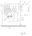
- FIG. 5 shows in a longitudinal section a modified with respect to the generation of the valve pressure part P 20 adjustment valve 20.
- the valve actuating pressure P 20 is different than in the adjustment of the FIG. 4 not by means of an additional partial flow in the Figures 3 and 4 the partial flow 17, but by means of to be controlled or regulated flow of the partial flow 16.
- Apart from this modification apply to the adjustment valve 20 of the Figures 3 and 4 made statements for the modified adjustment valve 20 and the comments made for this also for the adjustment valve 20 of the Figures 3 and 4 ,
- the adjusting valve 20 has a valve housing 21 and a valve piston 22 which can be moved axially back and forth in the valve housing 21 along a central valve axis S.
- a magnetic coil 27 and an armature 28 made of soft iron are represented by the adjusting device.
- the solenoid coil 27 is fixedly connected to the valve housing 21 and surrounds the armature 28.
- the armature 28 is connected to the valve piston 22 axially immovable, so that the valve piston 22 and the armature 28 axial movements such as to execute a unit.
- the valve piston 22 has a first active surface 23 and a second active surface 24 for the valve actuating pressure P 20 .
- the active surfaces 23 and 24 define axially together a fluid space 26 and are facing each other axially.
- the active surface 23, against which the valve actuating pressure P 20 of the valve spring 25 counteracts, is greater than the effective area 24, wherein in FIG. 5 the circumstances are exaggerated.
- the difference in size is only slightly, but defined so that the valve actuating pressure P 20 always exerts on the valve piston 22 a differential force corresponding to the size difference of the active surfaces 23 and 24, which counteracts the force of the valve spring 25.
- valve piston 22 can be made very accurate to the size difference of the active surfaces 23 and 24, and the differential force correspondingly small and the valve spring 25 advantageously softer than in the embodiment of FIG. 4 be. Correspondingly low forces required the adjusting device 27, 28.
- the adjustment valve 20 is more sensitive overall, and it can be the switching times of the adjustment valve 20 is shortened.
- the switching position of the adjusting valve 4 in the Figures 3 and 4 Port B opens into the fluid space 26 and the valve piston 22 separates the fluid space 26 and thus the inlet I from the other port A. Accordingly, the fluid of the partial flow 16 is returned to the pressure space 9 while the pressure space 8 is returned via the port A connected to the reservoir 11 and thus connected without pressure.
- the connection A is connected to the outlet O via a space of the valve housing 21, in which the valve spring 25 is arranged, and to the reservoir 11 via this.
- the magnetic coil 27 is energized and shifts the armature 28 against the force of the valve spring 25 in the axial direction first in the middle switching position and with a correspondingly long switch-on until the other extreme switching position , the first switch position.
- the valve piston 22 In the middle switching position, the valve piston 22 separates both ports A and B from the fluid chamber 26 into which the inlet I still opens.
- the valve piston 22 In the first switching position, the valve piston 22 assumes such an axial position that the fluid space 26 is in axial overlap with both the inlet I and the port A, while the valve piston 22 in the respective axial position the port B of the Fluid space 26 fluidly separates.
- the fluid of the partial flow 16 is passed through the fluid space 26 and the port A in the pressure chamber 8, while the pressure chamber 9 via the port B and a passage C of the valve piston 22 to the outlet O and finally connected to the reservoir 11 is.
- the valve piston 22 is hollow.
- the passage C is formed in a cylindrical jacket region of the valve piston 22, which adjoins the active surface 24 in the direction of the armature 28 and forms a narrow sealing gap with the surrounding jacket of the valve housing 21, which fluidically displaces the adjusting device 27, 28 from the fluid space 26 separates.
- a cylindrical jacket region of the valve piston 22, which forms a further narrow sealing gap with the valve housing 21, adjoins the active surface 23 radially on the outside and away from the adjusting device 27, 28, as long as the adjusting valve 20 does not assume the first shaft position, in which the valve piston 22 occupies the axial position in which the fluid space 26 is in axial overlap with the port A.
- the adjusting device 27, 28 with the associated control device switches the adjustment valve 20 over the entire operating range of the unit 14 and controls or regulates the axial position of the adjustment 5-7 and consequently the delivery volume of the positive displacement pump over the entire volume flow range, for the adapted supply of the unit 14 is required.
- the fluidic valve set pressure P 20 and the valve spring 25 serve as backup application in the event that the adjusting device 27, 28 or the associated control device fails due to a defect, for example due to a broken cable or a loose electrical connector.
- the adjustment valve 20 is designed so that in the event of failure, the delivery volume of the pump from maximum towards minimum is adjusted only upon reaching a fluid supply pressure P 14 , which is greater than a maximum fluid supply pressure P 14 , which is established with proper function of the adjustment valve 20 ,
- the valve spring 25 is installed with a biasing force which is greater than a force which exerts a maximum Ventilstelltik P 20 , which can be set with proper function, on the valve piston 22.
Landscapes
- Engineering & Computer Science (AREA)
- Mechanical Engineering (AREA)
- General Engineering & Computer Science (AREA)
- Details Of Reciprocating Pumps (AREA)
- Details And Applications Of Rotary Liquid Pumps (AREA)
- Safety Valves (AREA)
- Fluid-Driven Valves (AREA)
- Multiple-Way Valves (AREA)
- Magnetically Actuated Valves (AREA)
- Sliding Valves (AREA)
Priority Applications (1)
| Application Number | Priority Date | Filing Date | Title |
|---|---|---|---|
| EP16206318.4A EP3173624B1 (fr) | 2007-07-13 | 2008-07-09 | Pompe volumétrique avec soupape de réglage du volume d'alimentation |
Applications Claiming Priority (1)
| Application Number | Priority Date | Filing Date | Title |
|---|---|---|---|
| DE200710033146 DE102007033146B4 (de) | 2007-07-13 | 2007-07-13 | Verstellventil für die Verstellung des Fördervolumens einer Verdrängerpumpe |
Related Child Applications (2)
| Application Number | Title | Priority Date | Filing Date |
|---|---|---|---|
| EP16206318.4A Division EP3173624B1 (fr) | 2007-07-13 | 2008-07-09 | Pompe volumétrique avec soupape de réglage du volume d'alimentation |
| EP16206318.4A Division-Into EP3173624B1 (fr) | 2007-07-13 | 2008-07-09 | Pompe volumétrique avec soupape de réglage du volume d'alimentation |
Publications (4)
| Publication Number | Publication Date |
|---|---|
| EP2014919A2 true EP2014919A2 (fr) | 2009-01-14 |
| EP2014919A3 EP2014919A3 (fr) | 2010-09-01 |
| EP2014919B1 EP2014919B1 (fr) | 2017-01-04 |
| EP2014919B2 EP2014919B2 (fr) | 2020-01-08 |
Family
ID=39870297
Family Applications (2)
| Application Number | Title | Priority Date | Filing Date |
|---|---|---|---|
| EP16206318.4A Active EP3173624B1 (fr) | 2007-07-13 | 2008-07-09 | Pompe volumétrique avec soupape de réglage du volume d'alimentation |
| EP08159994.6A Not-in-force EP2014919B2 (fr) | 2007-07-13 | 2008-07-09 | Soupape de réglage pour le réglage du volume d'alimentation d'une pompe volumétrique |
Family Applications Before (1)
| Application Number | Title | Priority Date | Filing Date |
|---|---|---|---|
| EP16206318.4A Active EP3173624B1 (fr) | 2007-07-13 | 2008-07-09 | Pompe volumétrique avec soupape de réglage du volume d'alimentation |
Country Status (5)
| Country | Link |
|---|---|
| US (1) | US8523535B2 (fr) |
| EP (2) | EP3173624B1 (fr) |
| JP (1) | JP2009019773A (fr) |
| DE (1) | DE102007033146B4 (fr) |
| HU (1) | HUE035833T2 (fr) |
Cited By (2)
| Publication number | Priority date | Publication date | Assignee | Title |
|---|---|---|---|---|
| EP2836945A2 (fr) * | 2012-04-12 | 2015-02-18 | ITT Manufacturing Enterprises LLC | Procédé pour déterminer le débit d'une pompe dans des pompes volumétriques rotatives |
| US10451471B2 (en) | 2012-04-12 | 2019-10-22 | Itt Manufacturing Enterprises Llc | Method of determining pump flow in twin screw positive displacement pumps |
Families Citing this family (16)
| Publication number | Priority date | Publication date | Assignee | Title |
|---|---|---|---|---|
| DE102009060189B4 (de) | 2009-12-23 | 2017-07-13 | Schwäbische Hüttenwerke Automotive GmbH | Regelvorrichtung für die Verstellung des Fördervolumens einer Pumpe |
| DE102010038430B4 (de) * | 2010-07-26 | 2012-12-06 | Schwäbische Hüttenwerke Automotive GmbH | Verdrängerpumpe mit Absaugnut |
| DE102010039657B4 (de) * | 2010-08-23 | 2017-06-08 | Schwäbische Hüttenwerke Automotive GmbH | Bypassventil zur Regulierung eines Fluidflusses, zum Beispiel in einer Konstantpumpe |
| DE102011010834A1 (de) | 2011-02-10 | 2012-08-16 | Audi Ag | Verstelleinrichtung für einer Verdrängerpumpe |
| DE102011010835B4 (de) | 2011-02-10 | 2014-01-30 | Audi Ag | Verdrängerpumpe |
| DE102011013756A1 (de) * | 2011-03-12 | 2012-09-13 | Volkswagen Aktiengesellschaft | Zahnradpumpe mit Verschiebeeinheit zur Einstellung einer Fördermenge |
| JP5950583B2 (ja) * | 2011-03-27 | 2016-07-13 | 株式会社山田製作所 | ポンプ装置 |
| DE102011055407B4 (de) * | 2011-08-05 | 2018-10-04 | Hilite Germany Gmbh | Ventileinrichtung für eine Ölversorgungseinrichtung einer Kraftfahrzeug-Brennkraftmaschine |
| DE102013211900B4 (de) * | 2013-06-24 | 2025-10-16 | Zf Friedrichshafen Ag | Kolbenventil und Ventilkolben für ein Kolbenventil |
| JP2015117638A (ja) * | 2013-12-18 | 2015-06-25 | 株式会社山田製作所 | オイルポンプ装置 |
| DE102016212180A1 (de) | 2016-07-05 | 2018-01-11 | Volkswagen Aktiengesellschaft | Pumpe, Fluidsystem und Brennkraftmaschine |
| DE102017200876A1 (de) * | 2016-11-14 | 2018-05-17 | Mahle International Gmbh | Elektrische Kühlmittelpumpe |
| DE102017001318B4 (de) | 2017-02-11 | 2022-02-24 | Thomas Magnete Gmbh | Druckregelventil für eine Verstellpumpe |
| DE102017206619A1 (de) | 2017-04-20 | 2018-10-25 | Bayerische Motoren Werke Aktiengesellschaft | Kennfeld geregeltes Steuerventil für eine Schmiermittelpumpe |
| DE102017109061A1 (de) | 2017-04-27 | 2018-10-31 | Eto Magnetic Gmbh | Schieberproportionalventil für die Fördervolumenverstellung einer Verdrängerpumpe, Montageverfahren sowie System |
| CN110821582A (zh) * | 2019-11-18 | 2020-02-21 | 福建福清核电有限公司 | 一种汽轮机润滑油温度调节阀的稳定控制方法 |
Citations (13)
| Publication number | Priority date | Publication date | Assignee | Title |
|---|---|---|---|---|
| FR2326600A1 (fr) | 1975-10-04 | 1977-04-29 | Lucas Industries Ltd | Distributeurs pour pompes a course variable |
| DE3905937A1 (de) | 1989-02-25 | 1990-08-30 | Bosch Gmbh Robert | Verfahren und vorrichtung zur ansteuerung eines magnetventils |
| US5645352A (en) | 1993-07-27 | 1997-07-08 | Siemens Aktiengesellschaft | Circuit configuration and method for ascertaining the temperature of a current-regulated electrical coil |
| US5876185A (en) | 1996-11-20 | 1999-03-02 | Caterpillar Inc. | Load sensing pump control for a variable displacement pump |
| EP0908364A2 (fr) | 1997-10-09 | 1999-04-14 | General Motors Corporation | Méthode de fonctionnement d' une électrovanne |
| US6126420A (en) | 1996-12-04 | 2000-10-03 | Eisenmann; Siegfried | Infinitely variable ring gear pump |
| US6244839B1 (en) | 1997-11-14 | 2001-06-12 | University Of Arkansas | Pressure compensated variable displacement internal gear pumps |
| US6283735B1 (en) | 1998-10-13 | 2001-09-04 | SCHWäBISCHE HüTTENWERKE GMBH | Variable-delivery external gear pump |
| US6318818B1 (en) | 1998-12-22 | 2001-11-20 | Robert Bosch Gmbh | Method for compensating the temperature dependence of an inductive resistance of a valve coil |
| EP1262025A1 (fr) | 2000-01-25 | 2002-12-04 | Btg International Limited | Compression de donnees a rapidite de compression amelioree |
| WO2003058071A1 (fr) | 2002-01-12 | 2003-07-17 | Dieter Voigt | Dispositif pour reguler la pression de pompes hydrauliques |
| US6935851B2 (en) | 2002-08-28 | 2005-08-30 | SCHWäBISCHE HüTTENWERKE GMBH | External gear pump with pressure fluid pre-loading |
| US7726948B2 (en) | 2002-04-03 | 2010-06-01 | Slw Automotive Inc. | Hydraulic pump with variable flow and variable pressure and electric control |
Family Cites Families (36)
| Publication number | Priority date | Publication date | Assignee | Title |
|---|---|---|---|---|
| US1990750A (en) * | 1931-03-02 | 1935-02-12 | Gulf Res & Dev Corp | Variable volume pump and hydraulic transmission |
| DE1917488B2 (de) * | 1969-04-05 | 1977-06-23 | Robert Bosch Gmbh, 7000 Stuttgart | Steuereinrichtung fuer eine hydromaschine |
| JPS57131890A (en) * | 1981-02-06 | 1982-08-14 | Tokyo Keiki Co Ltd | Oil hydraulic controller |
| DE3109045A1 (de) * | 1981-03-10 | 1982-09-16 | Alfred Teves Gmbh, 6000 Frankfurt | Regelbare hydraulikpumpe |
| US4600364A (en) | 1983-06-20 | 1986-07-15 | Kabushiki Kaisha Komatsu Seisakusho | Fluid operated pump displacement control system |
| US4561521A (en) * | 1984-12-06 | 1985-12-31 | Ford Motor Company | Variable assist power steering system |
| KR900002409B1 (ko) * | 1986-01-11 | 1990-04-14 | 히다찌 겡끼 가부시끼가이샤 | 유압 구동장치의 펌프 입력마력 제어 시스템 |
| US4877099A (en) * | 1986-09-02 | 1989-10-31 | Ford Motor Company | Electronically controlled variable assist power steering system |
| JPH0544626Y2 (fr) * | 1988-05-25 | 1993-11-12 | ||
| JPH02161184A (ja) * | 1988-12-13 | 1990-06-21 | Daikin Ind Ltd | 可変容量形ポンプの制御回路 |
| DE3931962A1 (de) * | 1989-09-25 | 1991-04-04 | Rexroth Mannesmann Gmbh | Ansteuerelektronik fuer ein elektrisch verstellbares stellglied |
| US5029513A (en) * | 1990-04-27 | 1991-07-09 | Ford Motor Company | Variable-orifice, servo-solenoid valve for a variable-assist power steering system |
| US5392875A (en) * | 1991-12-23 | 1995-02-28 | Ford Motor Company | Hydraulic reaction variable assist power steering system |
| JPH0674206A (ja) * | 1992-08-26 | 1994-03-15 | Hitachi Constr Mach Co Ltd | 油圧モータ容量制御装置 |
| DE4308198C1 (de) * | 1993-03-15 | 1994-07-28 | Rexroth Mannesmann Gmbh | Drehmomentregelung über Schwenkwinkel bzw. Exzentrizität bei hydrostatischen Maschinen mit axialer und radialer Kolbenanordnung |
| US5297647A (en) * | 1993-03-18 | 1994-03-29 | Ford Motor Company | Variable assist power steering gear with hydraulic reaction controls |
| JPH08177745A (ja) * | 1994-12-21 | 1996-07-12 | Hitachi Constr Mach Co Ltd | 油圧ポンプ流量制御装置 |
| JPH08210195A (ja) * | 1995-02-06 | 1996-08-20 | Nissan Motor Co Ltd | ディーゼル機関の排気還流制御装置 |
| GB2320955B (en) * | 1997-01-03 | 1999-08-04 | Hobourn Automotive Ltd | Flow control valve |
| DE19854766A1 (de) * | 1998-11-27 | 2000-05-31 | Bosch Gmbh Robert | Kraftstoffeinspritzpumpe |
| JP4117588B2 (ja) * | 1999-02-12 | 2008-07-16 | 株式会社デンソー | 内燃機関の着火時期検出装置 |
| JP2001149921A (ja) * | 1999-11-25 | 2001-06-05 | Japan Organo Co Ltd | 水処理装置 |
| JP2001271616A (ja) * | 2000-01-18 | 2001-10-05 | Unisia Jecs Corp | 可変動弁機構の制御装置 |
| JP2001271758A (ja) * | 2000-03-24 | 2001-10-05 | Komatsu Ltd | エンジン回転数センシング機能を有する油圧回路 |
| US6896489B2 (en) | 2000-12-12 | 2005-05-24 | Borgwarner Inc. | Variable displacement vane pump with variable target regulator |
| JP3861594B2 (ja) * | 2000-12-15 | 2006-12-20 | ユニシア ジェーケーシー ステアリングシステム株式会社 | オイルポンプ |
| JP2002286151A (ja) * | 2001-03-26 | 2002-10-03 | Denso Corp | 電磁弁 |
| JP2002350199A (ja) * | 2001-05-24 | 2002-12-04 | Samson Co Ltd | 演算によって流量を算出する流量算出部を持った通水装置 |
| EP1350930B2 (fr) * | 2002-04-03 | 2016-01-27 | SLW Automotive Inc. | Pompe à déplacement variable et dispositif de contrôle |
| DE10324092B4 (de) * | 2003-05-27 | 2010-07-01 | Voigt, Dieter, Dipl.-Ing. | Regelbare Schmierölpumpe mit einem Fördermengenregler |
| DE102004002062A1 (de) * | 2004-01-15 | 2005-08-04 | Volkswagen Ag | Zahnradpumpe mit Fördermengenregelung |
| JP4202297B2 (ja) * | 2004-05-20 | 2008-12-24 | 株式会社日立製作所 | 内燃機関のバルブタイミング制御装置 |
| JP4214965B2 (ja) * | 2004-07-22 | 2009-01-28 | 株式会社デンソー | 蒸発燃料処理装置の漏れ検出装置 |
| US7130721B2 (en) * | 2004-10-29 | 2006-10-31 | Caterpillar Inc | Electrohydraulic control system |
| DE102005029086B4 (de) | 2005-06-23 | 2016-06-16 | Dr. Ing. H.C. F. Porsche Aktiengesellschaft | Ölpumpe für eine Brennkraftmaschine |
| US7993111B2 (en) * | 2008-01-03 | 2011-08-09 | Ford Global Technologies, Llc | Power steering pump flow control |
-
2007
- 2007-07-13 DE DE200710033146 patent/DE102007033146B4/de not_active Expired - Fee Related
-
2008
- 2008-07-09 HU HUE08159994A patent/HUE035833T2/en unknown
- 2008-07-09 EP EP16206318.4A patent/EP3173624B1/fr active Active
- 2008-07-09 EP EP08159994.6A patent/EP2014919B2/fr not_active Not-in-force
- 2008-07-11 US US12/171,559 patent/US8523535B2/en not_active Expired - Fee Related
- 2008-07-11 JP JP2008182053A patent/JP2009019773A/ja active Pending
Patent Citations (13)
| Publication number | Priority date | Publication date | Assignee | Title |
|---|---|---|---|---|
| FR2326600A1 (fr) | 1975-10-04 | 1977-04-29 | Lucas Industries Ltd | Distributeurs pour pompes a course variable |
| DE3905937A1 (de) | 1989-02-25 | 1990-08-30 | Bosch Gmbh Robert | Verfahren und vorrichtung zur ansteuerung eines magnetventils |
| US5645352A (en) | 1993-07-27 | 1997-07-08 | Siemens Aktiengesellschaft | Circuit configuration and method for ascertaining the temperature of a current-regulated electrical coil |
| US5876185A (en) | 1996-11-20 | 1999-03-02 | Caterpillar Inc. | Load sensing pump control for a variable displacement pump |
| US6126420A (en) | 1996-12-04 | 2000-10-03 | Eisenmann; Siegfried | Infinitely variable ring gear pump |
| EP0908364A2 (fr) | 1997-10-09 | 1999-04-14 | General Motors Corporation | Méthode de fonctionnement d' une électrovanne |
| US6244839B1 (en) | 1997-11-14 | 2001-06-12 | University Of Arkansas | Pressure compensated variable displacement internal gear pumps |
| US6283735B1 (en) | 1998-10-13 | 2001-09-04 | SCHWäBISCHE HüTTENWERKE GMBH | Variable-delivery external gear pump |
| US6318818B1 (en) | 1998-12-22 | 2001-11-20 | Robert Bosch Gmbh | Method for compensating the temperature dependence of an inductive resistance of a valve coil |
| EP1262025A1 (fr) | 2000-01-25 | 2002-12-04 | Btg International Limited | Compression de donnees a rapidite de compression amelioree |
| WO2003058071A1 (fr) | 2002-01-12 | 2003-07-17 | Dieter Voigt | Dispositif pour reguler la pression de pompes hydrauliques |
| US7726948B2 (en) | 2002-04-03 | 2010-06-01 | Slw Automotive Inc. | Hydraulic pump with variable flow and variable pressure and electric control |
| US6935851B2 (en) | 2002-08-28 | 2005-08-30 | SCHWäBISCHE HüTTENWERKE GMBH | External gear pump with pressure fluid pre-loading |
Cited By (3)
| Publication number | Priority date | Publication date | Assignee | Title |
|---|---|---|---|---|
| EP2836945A2 (fr) * | 2012-04-12 | 2015-02-18 | ITT Manufacturing Enterprises LLC | Procédé pour déterminer le débit d'une pompe dans des pompes volumétriques rotatives |
| US9678511B2 (en) | 2012-04-12 | 2017-06-13 | Itt Manufacturing Enterprises Llc. | Method of determining pump flow in rotary positive displacement pumps |
| US10451471B2 (en) | 2012-04-12 | 2019-10-22 | Itt Manufacturing Enterprises Llc | Method of determining pump flow in twin screw positive displacement pumps |
Also Published As
| Publication number | Publication date |
|---|---|
| US8523535B2 (en) | 2013-09-03 |
| EP2014919A3 (fr) | 2010-09-01 |
| JP2009019773A (ja) | 2009-01-29 |
| DE102007033146B4 (de) | 2012-02-02 |
| EP3173624A2 (fr) | 2017-05-31 |
| DE102007033146A1 (de) | 2009-01-15 |
| EP2014919B1 (fr) | 2017-01-04 |
| EP3173624B1 (fr) | 2022-01-26 |
| EP2014919B2 (fr) | 2020-01-08 |
| EP3173624A3 (fr) | 2017-06-21 |
| US20090041605A1 (en) | 2009-02-12 |
| HUE035833T2 (en) | 2018-05-28 |
Similar Documents
| Publication | Publication Date | Title |
|---|---|---|
| EP2014919B1 (fr) | Soupape de réglage pour le réglage du volume d'alimentation d'une pompe volumétrique | |
| DE60317399T3 (de) | Regelbare Verdrängerpump sowie Steursystem dafür | |
| DE112012000961B4 (de) | Hydraulische Einrichtung zur Betätigung einer Kupplung | |
| DE10237801C5 (de) | Vorrichtung zur Druckregelung von Hydraulikpumpen | |
| DE102013224112B4 (de) | Hydromaschine in Axialkolbenbauweise mit einer durch einen Proportionalmagneten verstellbaren Schrägscheiben-Stelleinrichtung | |
| DE112008000978T5 (de) | Hydraulische Pumpe mit variablem Durchfluss und Druck und verbesserter elektrischer Steuerung mit offenem Regelkreis | |
| WO1990002876A1 (fr) | Pompe a piston radiaux | |
| EP1356208A1 (fr) | Systeme de pompage comprenant une pompe hydraulique, destine notamment a un systeme de direction | |
| WO2012149929A2 (fr) | Pompe à cylindrée variable | |
| DE102010054100A1 (de) | Hydraulisches System | |
| DE102009037214B4 (de) | Verstellpumpe | |
| DE112019000570B4 (de) | Steuerventil mit alternierend öffnenden erstem und zweitem Kommunikationskanal und Kompressor, umfassend dieselbe | |
| WO1985004455A1 (fr) | Systeme hydraulique pour vehicules | |
| EP0305761A2 (fr) | Transmission hydrostatique à réglage secondaire à circuit ouvert | |
| DE102013008793B4 (de) | Verfahren und Vorrichtung zur Verstellung einer Verstellpumpe im offenen Hydraulikkreislauf | |
| DE60305812T2 (de) | Hydraulische Pumpe mit doppeltem Auslass und System mit derselben | |
| DE3443354A1 (de) | Hydraulikanlage | |
| WO2008077674A1 (fr) | Procédé de détermination d'un taux d'impulsions pour une soupape d'un dispositif de réglage d'arbre à cames | |
| DE10231197B4 (de) | Schmiermittelpumpanlage | |
| DE102013224113A1 (de) | Hydromotor | |
| DE102009060188B4 (de) | Verstellventil für die Verstellung des Fördervolumens einer Verdrängerpumpe mit Kaltstartfunktion | |
| EP4118334B1 (fr) | Dispositif de régulation d'une pompe hydraulique ou d'un moteur hydraulique | |
| DE102009060189B4 (de) | Regelvorrichtung für die Verstellung des Fördervolumens einer Pumpe | |
| DE3607138C2 (de) | Hydraulikanlage mit einer Steuereinrichtung | |
| DE102012223920A1 (de) | Rotationskolbenpumpe |
Legal Events
| Date | Code | Title | Description |
|---|---|---|---|
| PUAI | Public reference made under article 153(3) epc to a published international application that has entered the european phase |
Free format text: ORIGINAL CODE: 0009012 |
|
| AK | Designated contracting states |
Kind code of ref document: A2 Designated state(s): AT BE BG CH CY CZ DE DK EE ES FI FR GB GR HR HU IE IS IT LI LT LU LV MC MT NL NO PL PT RO SE SI SK TR |
|
| AX | Request for extension of the european patent |
Extension state: AL BA MK RS |
|
| RAP1 | Party data changed (applicant data changed or rights of an application transferred) |
Owner name: SCHWAEBISCHE HUETTENWERKE AUTOMOTIVE GMBH |
|
| PUAL | Search report despatched |
Free format text: ORIGINAL CODE: 0009013 |
|
| AK | Designated contracting states |
Kind code of ref document: A3 Designated state(s): AT BE BG CH CY CZ DE DK EE ES FI FR GB GR HR HU IE IS IT LI LT LU LV MC MT NL NO PL PT RO SE SI SK TR |
|
| AX | Request for extension of the european patent |
Extension state: AL BA MK RS |
|
| 17P | Request for examination filed |
Effective date: 20110118 |
|
| AKX | Designation fees paid |
Designated state(s): AT BE BG CH CY CZ DE DK EE ES FI FR GB GR HR HU IE IS IT LI LT LU LV MC MT NL NO PL PT RO SE SI SK TR |
|
| TPAC | Observations filed by third parties |
Free format text: ORIGINAL CODE: EPIDOSNTIPA |
|
| TPAC | Observations filed by third parties |
Free format text: ORIGINAL CODE: EPIDOSNTIPA |
|
| 17Q | First examination report despatched |
Effective date: 20150218 |
|
| GRAP | Despatch of communication of intention to grant a patent |
Free format text: ORIGINAL CODE: EPIDOSNIGR1 |
|
| INTG | Intention to grant announced |
Effective date: 20160726 |
|
| STAA | Information on the status of an ep patent application or granted ep patent |
Free format text: STATUS: GRANT OF PATENT IS INTENDED |
|
| GRAS | Grant fee paid |
Free format text: ORIGINAL CODE: EPIDOSNIGR3 |
|
| GRAA | (expected) grant |
Free format text: ORIGINAL CODE: 0009210 |
|
| STAA | Information on the status of an ep patent application or granted ep patent |
Free format text: STATUS: THE PATENT HAS BEEN GRANTED |
|
| AK | Designated contracting states |
Kind code of ref document: B1 Designated state(s): AT BE BG CH CY CZ DE DK EE ES FI FR GB GR HR HU IE IS IT LI LT LU LV MC MT NL NO PL PT RO SE SI SK TR |
|
| REG | Reference to a national code |
Ref country code: GB Ref legal event code: FG4D Free format text: NOT ENGLISH |
|
| REG | Reference to a national code |
Ref country code: CH Ref legal event code: EP |
|
| REG | Reference to a national code |
Ref country code: AT Ref legal event code: REF Ref document number: 859517 Country of ref document: AT Kind code of ref document: T Effective date: 20170115 |
|
| REG | Reference to a national code |
Ref country code: IE Ref legal event code: FG4D Free format text: LANGUAGE OF EP DOCUMENT: GERMAN |
|
| REG | Reference to a national code |
Ref country code: DE Ref legal event code: R096 Ref document number: 502008014928 Country of ref document: DE |
|
| REG | Reference to a national code |
Ref country code: LT Ref legal event code: MG4D Ref country code: NL Ref legal event code: MP Effective date: 20170104 |
|
| PG25 | Lapsed in a contracting state [announced via postgrant information from national office to epo] |
Ref country code: NL Free format text: LAPSE BECAUSE OF FAILURE TO SUBMIT A TRANSLATION OF THE DESCRIPTION OR TO PAY THE FEE WITHIN THE PRESCRIBED TIME-LIMIT Effective date: 20170104 |
|
| REG | Reference to a national code |
Ref country code: FR Ref legal event code: PLFP Year of fee payment: 10 |
|
| PG25 | Lapsed in a contracting state [announced via postgrant information from national office to epo] |
Ref country code: HR Free format text: LAPSE BECAUSE OF FAILURE TO SUBMIT A TRANSLATION OF THE DESCRIPTION OR TO PAY THE FEE WITHIN THE PRESCRIBED TIME-LIMIT Effective date: 20170104 Ref country code: LT Free format text: LAPSE BECAUSE OF FAILURE TO SUBMIT A TRANSLATION OF THE DESCRIPTION OR TO PAY THE FEE WITHIN THE PRESCRIBED TIME-LIMIT Effective date: 20170104 Ref country code: GR Free format text: LAPSE BECAUSE OF FAILURE TO SUBMIT A TRANSLATION OF THE DESCRIPTION OR TO PAY THE FEE WITHIN THE PRESCRIBED TIME-LIMIT Effective date: 20170405 Ref country code: FI Free format text: LAPSE BECAUSE OF FAILURE TO SUBMIT A TRANSLATION OF THE DESCRIPTION OR TO PAY THE FEE WITHIN THE PRESCRIBED TIME-LIMIT Effective date: 20170104 Ref country code: IS Free format text: LAPSE BECAUSE OF FAILURE TO SUBMIT A TRANSLATION OF THE DESCRIPTION OR TO PAY THE FEE WITHIN THE PRESCRIBED TIME-LIMIT Effective date: 20170504 Ref country code: NO Free format text: LAPSE BECAUSE OF FAILURE TO SUBMIT A TRANSLATION OF THE DESCRIPTION OR TO PAY THE FEE WITHIN THE PRESCRIBED TIME-LIMIT Effective date: 20170404 |
|
| PG25 | Lapsed in a contracting state [announced via postgrant information from national office to epo] |
Ref country code: SE Free format text: LAPSE BECAUSE OF FAILURE TO SUBMIT A TRANSLATION OF THE DESCRIPTION OR TO PAY THE FEE WITHIN THE PRESCRIBED TIME-LIMIT Effective date: 20170104 Ref country code: BG Free format text: LAPSE BECAUSE OF FAILURE TO SUBMIT A TRANSLATION OF THE DESCRIPTION OR TO PAY THE FEE WITHIN THE PRESCRIBED TIME-LIMIT Effective date: 20170404 Ref country code: ES Free format text: LAPSE BECAUSE OF FAILURE TO SUBMIT A TRANSLATION OF THE DESCRIPTION OR TO PAY THE FEE WITHIN THE PRESCRIBED TIME-LIMIT Effective date: 20170104 Ref country code: PL Free format text: LAPSE BECAUSE OF FAILURE TO SUBMIT A TRANSLATION OF THE DESCRIPTION OR TO PAY THE FEE WITHIN THE PRESCRIBED TIME-LIMIT Effective date: 20170104 Ref country code: LV Free format text: LAPSE BECAUSE OF FAILURE TO SUBMIT A TRANSLATION OF THE DESCRIPTION OR TO PAY THE FEE WITHIN THE PRESCRIBED TIME-LIMIT Effective date: 20170104 Ref country code: PT Free format text: LAPSE BECAUSE OF FAILURE TO SUBMIT A TRANSLATION OF THE DESCRIPTION OR TO PAY THE FEE WITHIN THE PRESCRIBED TIME-LIMIT Effective date: 20170504 |
|
| REG | Reference to a national code |
Ref country code: DE Ref legal event code: R026 Ref document number: 502008014928 Country of ref document: DE |
|
| PLBI | Opposition filed |
Free format text: ORIGINAL CODE: 0009260 |
|
| PG25 | Lapsed in a contracting state [announced via postgrant information from national office to epo] |
Ref country code: SK Free format text: LAPSE BECAUSE OF FAILURE TO SUBMIT A TRANSLATION OF THE DESCRIPTION OR TO PAY THE FEE WITHIN THE PRESCRIBED TIME-LIMIT Effective date: 20170104 Ref country code: EE Free format text: LAPSE BECAUSE OF FAILURE TO SUBMIT A TRANSLATION OF THE DESCRIPTION OR TO PAY THE FEE WITHIN THE PRESCRIBED TIME-LIMIT Effective date: 20170104 Ref country code: RO Free format text: LAPSE BECAUSE OF FAILURE TO SUBMIT A TRANSLATION OF THE DESCRIPTION OR TO PAY THE FEE WITHIN THE PRESCRIBED TIME-LIMIT Effective date: 20170104 Ref country code: CZ Free format text: LAPSE BECAUSE OF FAILURE TO SUBMIT A TRANSLATION OF THE DESCRIPTION OR TO PAY THE FEE WITHIN THE PRESCRIBED TIME-LIMIT Effective date: 20170104 |
|
| PLAX | Notice of opposition and request to file observation + time limit sent |
Free format text: ORIGINAL CODE: EPIDOSNOBS2 |
|
| 26 | Opposition filed |
Opponent name: BONTAZ CENTRE R&D Effective date: 20171002 |
|
| PG25 | Lapsed in a contracting state [announced via postgrant information from national office to epo] |
Ref country code: DK Free format text: LAPSE BECAUSE OF FAILURE TO SUBMIT A TRANSLATION OF THE DESCRIPTION OR TO PAY THE FEE WITHIN THE PRESCRIBED TIME-LIMIT Effective date: 20170104 |
|
| PG25 | Lapsed in a contracting state [announced via postgrant information from national office to epo] |
Ref country code: SI Free format text: LAPSE BECAUSE OF FAILURE TO SUBMIT A TRANSLATION OF THE DESCRIPTION OR TO PAY THE FEE WITHIN THE PRESCRIBED TIME-LIMIT Effective date: 20170104 |
|
| REG | Reference to a national code |
Ref country code: CH Ref legal event code: PL |
|
| PLBB | Reply of patent proprietor to notice(s) of opposition received |
Free format text: ORIGINAL CODE: EPIDOSNOBS3 |
|
| REG | Reference to a national code |
Ref country code: IE Ref legal event code: MM4A |
|
| PG25 | Lapsed in a contracting state [announced via postgrant information from national office to epo] |
Ref country code: LI Free format text: LAPSE BECAUSE OF NON-PAYMENT OF DUE FEES Effective date: 20170731 Ref country code: IE Free format text: LAPSE BECAUSE OF NON-PAYMENT OF DUE FEES Effective date: 20170709 Ref country code: CH Free format text: LAPSE BECAUSE OF NON-PAYMENT OF DUE FEES Effective date: 20170731 |
|
| REG | Reference to a national code |
Ref country code: HU Ref legal event code: AG4A Ref document number: E035833 Country of ref document: HU |
|
| REG | Reference to a national code |
Ref country code: BE Ref legal event code: MM Effective date: 20170731 |
|
| PG25 | Lapsed in a contracting state [announced via postgrant information from national office to epo] |
Ref country code: LU Free format text: LAPSE BECAUSE OF NON-PAYMENT OF DUE FEES Effective date: 20170709 |
|
| REG | Reference to a national code |
Ref country code: FR Ref legal event code: PLFP Year of fee payment: 11 |
|
| PG25 | Lapsed in a contracting state [announced via postgrant information from national office to epo] |
Ref country code: BE Free format text: LAPSE BECAUSE OF NON-PAYMENT OF DUE FEES Effective date: 20170731 |
|
| REG | Reference to a national code |
Ref country code: AT Ref legal event code: MM01 Ref document number: 859517 Country of ref document: AT Kind code of ref document: T Effective date: 20170709 |
|
| PG25 | Lapsed in a contracting state [announced via postgrant information from national office to epo] |
Ref country code: MT Free format text: LAPSE BECAUSE OF FAILURE TO SUBMIT A TRANSLATION OF THE DESCRIPTION OR TO PAY THE FEE WITHIN THE PRESCRIBED TIME-LIMIT Effective date: 20170104 |
|
| PG25 | Lapsed in a contracting state [announced via postgrant information from national office to epo] |
Ref country code: AT Free format text: LAPSE BECAUSE OF NON-PAYMENT OF DUE FEES Effective date: 20170709 |
|
| PLBP | Opposition withdrawn |
Free format text: ORIGINAL CODE: 0009264 |
|
| PG25 | Lapsed in a contracting state [announced via postgrant information from national office to epo] |
Ref country code: MC Free format text: LAPSE BECAUSE OF FAILURE TO SUBMIT A TRANSLATION OF THE DESCRIPTION OR TO PAY THE FEE WITHIN THE PRESCRIBED TIME-LIMIT Effective date: 20170104 |
|
| REG | Reference to a national code |
Ref country code: GB Ref legal event code: 732E Free format text: REGISTERED BETWEEN 20190627 AND 20190703 |
|
| PG25 | Lapsed in a contracting state [announced via postgrant information from national office to epo] |
Ref country code: CY Free format text: LAPSE BECAUSE OF NON-PAYMENT OF DUE FEES Effective date: 20170104 |
|
| PUAH | Patent maintained in amended form |
Free format text: ORIGINAL CODE: 0009272 |
|
| STAA | Information on the status of an ep patent application or granted ep patent |
Free format text: STATUS: PATENT MAINTAINED AS AMENDED |
|
| 27A | Patent maintained in amended form |
Effective date: 20200108 |
|
| AK | Designated contracting states |
Kind code of ref document: B2 Designated state(s): AT BE BG CH CY CZ DE DK EE ES FI FR GB GR HR HU IE IS IT LI LT LU LV MC MT NL NO PL PT RO SE SI SK TR |
|
| REG | Reference to a national code |
Ref country code: DE Ref legal event code: R102 Ref document number: 502008014928 Country of ref document: DE |
|
| PG25 | Lapsed in a contracting state [announced via postgrant information from national office to epo] |
Ref country code: TR Free format text: LAPSE BECAUSE OF FAILURE TO SUBMIT A TRANSLATION OF THE DESCRIPTION OR TO PAY THE FEE WITHIN THE PRESCRIBED TIME-LIMIT Effective date: 20170104 |
|
| P01 | Opt-out of the competence of the unified patent court (upc) registered |
Effective date: 20230515 |
|
| PGFP | Annual fee paid to national office [announced via postgrant information from national office to epo] |
Ref country code: IT Payment date: 20230724 Year of fee payment: 16 Ref country code: GB Payment date: 20230720 Year of fee payment: 16 |
|
| PGFP | Annual fee paid to national office [announced via postgrant information from national office to epo] |
Ref country code: HU Payment date: 20230721 Year of fee payment: 16 Ref country code: FR Payment date: 20230725 Year of fee payment: 16 |
|
| PGFP | Annual fee paid to national office [announced via postgrant information from national office to epo] |
Ref country code: DE Payment date: 20240719 Year of fee payment: 17 |
|
| GBPC | Gb: european patent ceased through non-payment of renewal fee |
Effective date: 20240709 |
|
| PG25 | Lapsed in a contracting state [announced via postgrant information from national office to epo] |
Ref country code: HU Free format text: LAPSE BECAUSE OF NON-PAYMENT OF DUE FEES Effective date: 20240710 |
|
| PG25 | Lapsed in a contracting state [announced via postgrant information from national office to epo] |
Ref country code: FR Free format text: LAPSE BECAUSE OF NON-PAYMENT OF DUE FEES Effective date: 20240731 |
|
| PG25 | Lapsed in a contracting state [announced via postgrant information from national office to epo] |
Ref country code: GB Free format text: LAPSE BECAUSE OF NON-PAYMENT OF DUE FEES Effective date: 20240709 |
|
| PG25 | Lapsed in a contracting state [announced via postgrant information from national office to epo] |
Ref country code: IT Free format text: LAPSE BECAUSE OF NON-PAYMENT OF DUE FEES Effective date: 20240709 |
|
| REG | Reference to a national code |
Ref country code: DE Ref legal event code: R119 Ref document number: 502008014928 Country of ref document: DE |
|
| PG25 | Lapsed in a contracting state [announced via postgrant information from national office to epo] |
Ref country code: DE Free format text: LAPSE BECAUSE OF NON-PAYMENT OF DUE FEES Effective date: 20260203 |