EP2014936A2 - Laufrolle - Google Patents
Laufrolle Download PDFInfo
- Publication number
- EP2014936A2 EP2014936A2 EP08160364A EP08160364A EP2014936A2 EP 2014936 A2 EP2014936 A2 EP 2014936A2 EP 08160364 A EP08160364 A EP 08160364A EP 08160364 A EP08160364 A EP 08160364A EP 2014936 A2 EP2014936 A2 EP 2014936A2
- Authority
- EP
- European Patent Office
- Prior art keywords
- facing surface
- outer ring
- self
- radially outwardly
- outwardly facing
- Prior art date
- Legal status (The legal status is an assumption and is not a legal conclusion. Google has not performed a legal analysis and makes no representation as to the accuracy of the status listed.)
- Granted
Links
Images

Classifications
-
- F—MECHANICAL ENGINEERING; LIGHTING; HEATING; WEAPONS; BLASTING
- F16—ENGINEERING ELEMENTS AND UNITS; GENERAL MEASURES FOR PRODUCING AND MAINTAINING EFFECTIVE FUNCTIONING OF MACHINES OR INSTALLATIONS; THERMAL INSULATION IN GENERAL
- F16C—SHAFTS; FLEXIBLE SHAFTS; ELEMENTS OR CRANKSHAFT MECHANISMS; ROTARY BODIES OTHER THAN GEARING ELEMENTS; BEARINGS
- F16C13/00—Rolls, drums, discs, or the like; Bearings or mountings therefor
- F16C13/006—Guiding rollers, wheels or the like, formed by or on the outer element of a single bearing or bearing unit, e.g. two adjacent bearings, whose ratio of length to diameter is generally less than one
-
- F—MECHANICAL ENGINEERING; LIGHTING; HEATING; WEAPONS; BLASTING
- F16—ENGINEERING ELEMENTS AND UNITS; GENERAL MEASURES FOR PRODUCING AND MAINTAINING EFFECTIVE FUNCTIONING OF MACHINES OR INSTALLATIONS; THERMAL INSULATION IN GENERAL
- F16C—SHAFTS; FLEXIBLE SHAFTS; ELEMENTS OR CRANKSHAFT MECHANISMS; ROTARY BODIES OTHER THAN GEARING ELEMENTS; BEARINGS
- F16C33/00—Parts of bearings; Special methods for making bearings or parts thereof
- F16C33/02—Parts of sliding-contact bearings
- F16C33/04—Brasses; Bushes; Linings
- F16C33/20—Sliding surface consisting mainly of plastics
-
- F—MECHANICAL ENGINEERING; LIGHTING; HEATING; WEAPONS; BLASTING
- F16—ENGINEERING ELEMENTS AND UNITS; GENERAL MEASURES FOR PRODUCING AND MAINTAINING EFFECTIVE FUNCTIONING OF MACHINES OR INSTALLATIONS; THERMAL INSULATION IN GENERAL
- F16C—SHAFTS; FLEXIBLE SHAFTS; ELEMENTS OR CRANKSHAFT MECHANISMS; ROTARY BODIES OTHER THAN GEARING ELEMENTS; BEARINGS
- F16C33/00—Parts of bearings; Special methods for making bearings or parts thereof
- F16C33/02—Parts of sliding-contact bearings
- F16C33/04—Brasses; Bushes; Linings
- F16C33/20—Sliding surface consisting mainly of plastics
- F16C33/208—Methods of manufacture, e.g. shaping, applying coatings
-
- F—MECHANICAL ENGINEERING; LIGHTING; HEATING; WEAPONS; BLASTING
- F16—ENGINEERING ELEMENTS AND UNITS; GENERAL MEASURES FOR PRODUCING AND MAINTAINING EFFECTIVE FUNCTIONING OF MACHINES OR INSTALLATIONS; THERMAL INSULATION IN GENERAL
- F16C—SHAFTS; FLEXIBLE SHAFTS; ELEMENTS OR CRANKSHAFT MECHANISMS; ROTARY BODIES OTHER THAN GEARING ELEMENTS; BEARINGS
- F16C2208/00—Plastics; Synthetic resins, e.g. rubbers
- F16C2208/02—Plastics; Synthetic resins, e.g. rubbers comprising fillers, fibres
- F16C2208/04—Glass fibres
-
- F—MECHANICAL ENGINEERING; LIGHTING; HEATING; WEAPONS; BLASTING
- F16—ENGINEERING ELEMENTS AND UNITS; GENERAL MEASURES FOR PRODUCING AND MAINTAINING EFFECTIVE FUNCTIONING OF MACHINES OR INSTALLATIONS; THERMAL INSULATION IN GENERAL
- F16C—SHAFTS; FLEXIBLE SHAFTS; ELEMENTS OR CRANKSHAFT MECHANISMS; ROTARY BODIES OTHER THAN GEARING ELEMENTS; BEARINGS
- F16C2208/00—Plastics; Synthetic resins, e.g. rubbers
- F16C2208/10—Elastomers; Rubbers
-
- F—MECHANICAL ENGINEERING; LIGHTING; HEATING; WEAPONS; BLASTING
- F16—ENGINEERING ELEMENTS AND UNITS; GENERAL MEASURES FOR PRODUCING AND MAINTAINING EFFECTIVE FUNCTIONING OF MACHINES OR INSTALLATIONS; THERMAL INSULATION IN GENERAL
- F16C—SHAFTS; FLEXIBLE SHAFTS; ELEMENTS OR CRANKSHAFT MECHANISMS; ROTARY BODIES OTHER THAN GEARING ELEMENTS; BEARINGS
- F16C2208/00—Plastics; Synthetic resins, e.g. rubbers
- F16C2208/20—Thermoplastic resins
- F16C2208/30—Fluoropolymers
- F16C2208/32—Polytetrafluorethylene [PTFE]
-
- F—MECHANICAL ENGINEERING; LIGHTING; HEATING; WEAPONS; BLASTING
- F16—ENGINEERING ELEMENTS AND UNITS; GENERAL MEASURES FOR PRODUCING AND MAINTAINING EFFECTIVE FUNCTIONING OF MACHINES OR INSTALLATIONS; THERMAL INSULATION IN GENERAL
- F16C—SHAFTS; FLEXIBLE SHAFTS; ELEMENTS OR CRANKSHAFT MECHANISMS; ROTARY BODIES OTHER THAN GEARING ELEMENTS; BEARINGS
- F16C2208/00—Plastics; Synthetic resins, e.g. rubbers
- F16C2208/20—Thermoplastic resins
- F16C2208/70—Polyesters, e.g. polyethylene-terephthlate [PET], polybutylene-terephthlate [PBT]
-
- F—MECHANICAL ENGINEERING; LIGHTING; HEATING; WEAPONS; BLASTING
- F16—ENGINEERING ELEMENTS AND UNITS; GENERAL MEASURES FOR PRODUCING AND MAINTAINING EFFECTIVE FUNCTIONING OF MACHINES OR INSTALLATIONS; THERMAL INSULATION IN GENERAL
- F16C—SHAFTS; FLEXIBLE SHAFTS; ELEMENTS OR CRANKSHAFT MECHANISMS; ROTARY BODIES OTHER THAN GEARING ELEMENTS; BEARINGS
- F16C2223/00—Surface treatments; Hardening; Coating
- F16C2223/10—Hardening, e.g. carburizing, carbo-nitriding
- F16C2223/14—Hardening, e.g. carburizing, carbo-nitriding with nitriding
-
- Y—GENERAL TAGGING OF NEW TECHNOLOGICAL DEVELOPMENTS; GENERAL TAGGING OF CROSS-SECTIONAL TECHNOLOGIES SPANNING OVER SEVERAL SECTIONS OF THE IPC; TECHNICAL SUBJECTS COVERED BY FORMER USPC CROSS-REFERENCE ART COLLECTIONS [XRACs] AND DIGESTS
- Y10—TECHNICAL SUBJECTS COVERED BY FORMER USPC
- Y10T—TECHNICAL SUBJECTS COVERED BY FORMER US CLASSIFICATION
- Y10T29/00—Metal working
- Y10T29/49—Method of mechanical manufacture
- Y10T29/49636—Process for making bearing or component thereof
- Y10T29/49643—Rotary bearing
- Y10T29/49679—Anti-friction bearing or component thereof
- Y10T29/49689—Race making
-
- Y—GENERAL TAGGING OF NEW TECHNOLOGICAL DEVELOPMENTS; GENERAL TAGGING OF CROSS-SECTIONAL TECHNOLOGIES SPANNING OVER SEVERAL SECTIONS OF THE IPC; TECHNICAL SUBJECTS COVERED BY FORMER USPC CROSS-REFERENCE ART COLLECTIONS [XRACs] AND DIGESTS
- Y10—TECHNICAL SUBJECTS COVERED BY FORMER USPC
- Y10T—TECHNICAL SUBJECTS COVERED BY FORMER US CLASSIFICATION
- Y10T29/00—Metal working
- Y10T29/49—Method of mechanical manufacture
- Y10T29/49636—Process for making bearing or component thereof
- Y10T29/49702—Lubricating
Definitions
- the present invention relates generally to a track roller.
- the present invention relates to a self-lubricating track roller with a resilient tire bonded to an outer ring.
- U.S. Pat. No. 5,398,294 discloses a track roller with a self-lubricating material bonded to the inner ring.
- the track roller is created by injecting the self-lubricating material between the inner ring and an outer ring and then curing the self-lubricating material.
- the inner ring may be swaged to form inclined axial bearing surfaces. During use, these surfaces will resist axial forces that could cause separation of the inner ring and the outer ring.
- This track roller includes a self-lubricating liner material bonded via adhesive to a radially outwardly facing surface of an inner ring.
- a heat shrinkable tubing assembly fixture is used to securely adhere the self-lubricating liner material to the inner ring.
- the inner ring is then assembled with an outer ring to form a self-lubricating track roller.
- self-lubricating track rollers are particularly susceptible to binding as a result of contamination or abrasion at the sliding interface (i.e., the interface between the self-lubricating surface and the adjacent sliding surface). If the friction at the sliding interface exceeds the friction between the surfaces at other roller interfaces, then the surfaces at the other roller interfaces may slide past one another causing undesired wear damage. For example, such wear damage may occur at the interface between two components of the track roller or between the track roller and the object that the track roller is transporting (i.e., a conveyor belt or an object being directly transported on the track roller). In either case, the binding at the sliding interface results in damage to the track roller or another item in the motive assembly.
- track rollers are commonly subjected to vibrations and oscillations that may result in fretting or corrosion damage. These vibrations and oscillations can occur from the use of the track roller itself, the use of other machines in the vicinity of the track roller, or both. If the track roller is stationary when it is subjected to vibration, then the vibration can cause the selective degradation of a portion of the surface at the sliding interface. This selective degradation in turn may create asymmetries along the sliding interface that can interrupt the smooth rotation of the roller or provide a gap that permits contaminants to encroach on the sliding interface.
- the present invention provides a self-lubricating track roller and method of making a self-lubricating track roller.
- the self-lubricating track roller of this invention provides a self-lubricating material with a surface profile that closely matches the surface profile of the adjacent sliding surface to reduce exposure of the sliding interface to contaminants.
- the present invention provides a method of making a self-lubricating track roller.
- the method includes providing an inner ring having a radially outwardly facing surface.
- a parting agent is applied onto the radially outwardly facing surface of the inner ring.
- a self-lubricating material is applied over the radially outwardly facing surface of the inner ring.
- an outer ring is formed around the self-lubricating material such that a radially inwardly facing surface of the outer ring bonds to the self-lubricating material.
- a resilient tire is bonded onto a radially outwardly facing surface of the outer ring.
- the step of forming an outer ring around the self-lubricating material such that the radially inwardly facing surface of the outer ring bonds to the self-lubricated material may include (1) wrapping resin soaked filaments around the self-lubricating material and the radially outwardly facing surface of the inner ring and (2) curing resin soaked filaments to form an outer ring having a radially outwardly facing surface.
- a radial groove may be formed on one of the radially outwardly facing surface of the inner ring and the radially inwardly facing surface of the outer ring. Further, a radial ridge may be formed on the other of the radially outwardly facing surface of the inner ring and the radially inwardly facing surface of the outer ring. The radial groove and the radial ridge may act to resist axial forces acting on the inner ring and the outer ring.
- the tire and its relationship to the outer ring may be further defined.
- a radial groove may be formed on one of the radially outwardly facing surface of the outer ring and a radially inwardly facing surface of the resilient tire.
- a corresponding radial ridge may be formed on the other of the radially outwardly facing surface of the outer ring and the radially inwardly facing surface of the resilient tire.
- the radial groove and radial ridge may resist axial forces acting on the outer ring and the resilent tire.
- Reinforcements may be embedded surrounding the outer ring and the tire. Grooves may be formed in a radially outwardly facing surface of the tire.
- the step of bonding the tire onto the radially outwardly facing surface of the outer ring may include molding the tire over the radially outwardly facing surface of the outer ring.
- the tire may be formed from an elastomeric material. Additionally, to rough the surface of the outer ring for improved bonding, the radially outerwardly facing surface of the outer ring may be machined prior to bonding the tire thereto.
- the surface of the inner ring to is treated to resist corrosion.
- the self-lubricating track roller made by the method is also within the scope of the invention.
- there may be a radially outwardly facing surface of the inner ring has a surface profile that corresponds to a mating surface profile of the the self-lubricating material to prevent entry of contaminants into a sliding interface between the inner ring and the self-lubricating material.
- the present invention also provides a self-lubricating track roller.
- the self-lubricating track roller includes an inner ring having a radially outwardly facing surface and an outer ring having a radially outwardly facing surface and a radially inwardly facing surface.
- a self-lubricating material is bonded to the radially inwardly facing surface of the outer ring such that the outer ring slidably surrounds the radially outwardly facing surface of the inner ring.
- a resilient tire is bonded to the outer surface of the outer ring.
- the radially outwardly facing surface of the inner ring has a surface profile that corresponds to a mating surface profile of the self-lubricating material that is bonded to the radially inwardly facing surface of the outer ring.
- the outer ring may include cured resin soaked filaments wrapped around a self-lubricating fabric.
- one of the radially outwardly facing surface of the inner ring and the radially inwardly facing surface of the outer ring may include a radial groove and the other of the radially outwardly facing surface of the inner ring and the radially inwardly facing surface of the outer ring may have a radial ridge extending into the groove to resist axial forces acting on the inner ring and the outer ring.
- one of the radially outwardly facing surface of the outer ring and a radially inwardly facing surface of the resilient tire may include a radial groove and the other of the radially outwardly facing surface of the outer ring and the radially inwardly facing surface of the resilient tire may have a radial ridge extending into the groove to resist axial forces acting on the outer ring and the resilient tire.
- the tire may have other features. Reinforcements may be embedded in the tire and surround the outer ring.
- the tire may have grooves formed in a radially outwardly facing surface of the tire. Further, the tire may be formed from an elastomeric material.
- the inner ring may be metallic. Further, the inner ring may be surface treated to resist corrosion.
- the present invention provides a track roller that is less likely to be damaged and does not require an external lubrication source.
- This objective is accomplished by including an inner ring and a resilient tire bonded to the radially outwardly facing surface of the outer ring.
- the inner ring is treated to resist vibration and oscillation damage.
- the objective is also accomplished by providing a self-lubricating surface, which eliminates the need for an external lubrication source.
- the resilient tire provides higher friction between the radially outwardly facing surface of the track roller and the contact surface, which reduces the likeliness of sliding damage.
- the present invention also provides an efficient manufacturing process for the assembly of the track roller. Generally, this includes applying a parting agent onto the radially outwardly facing surface of the inner ring, applying the self-lubricating material over the radially outwardly facing surface, wrapping a material around the self-lubricating material to form the outer ring, and bonding the resilient tire onto the radially outwardly facing surface of the outer ring.
- FIG. 1 is a cross-sectional view of a track roller incorporating the present invention.
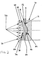
- FIG. 2 is an enlarged cross-sectional view of the track roller of FIG. 1 .
- a self-lubricating track roller 10 including an inner ring 12 and an outer ring 16 with a self-lubricating material 15 forming a portion of a sliding interface therebetween.
- a resilient tire 22 may be placed on or formed around a radially outwardly facing surface 20 of the outer ring 16 to contact a track (not shown), conveying surface, or object being transported.
- the self-lubricating material 15 provides a sliding interface between the inner ring 12 and the outer ring 16 permitting the rotation of one relative to the other.
- the self-lubricating material 15 is bonded to the body of the outer ring 16 to form a radially inwardly facing surface 18.
- the outer ring 16 slideably surrounds the radially outwardly facing surface 14 of the inner ring 12.
- the radially outwardly facing surface 14 of the inner ring 12 may be bonded to the self-lubricating material 15, such that the radially inwardly facing surface 18 of the outer ring 16 slidably surrounds the self-lubricating material 15 bonded to the inner ring 12.
- the self-lubricating material 15 can be any one of a number of self-lubricating materials such as, for example, a polytetrafluoroethylene resin soaked fabric, Teflon ® , and the like.
- the inner ring 12 may be metallic and have at least the radially outwardly facing surface 14 surface treated to resist corrosion and fretting damage.
- the surface treatment may include, but is not limited to, electroless nickel plating, hard chrome plating, or a salt nitriding process.
- a corrosion and fret resistant inner ring 12 is preferable, the inner ring 12 can be formed from any material, such as plastic, resin soaked filaments, and the like.
- the body of the outer ring 16 is formed from cured resin-soaked fiberglass filaments.
- the body could also be metallic, non-metallic, or a composite material without departing from the scope of the invention.
- a groove-ridge structure between the inner ring 12 and the outer ring 16 may be used to resist axial forces on the self-lubricating track roller 10.
- the radially outwardly facing surface 14 of the inner ring 12 includes a radial groove 24.
- the radially inwardly facing surface 18 of the outer ring 16 includes a radial ridge 26.
- the radial ridge 26 extends into the radial groove 24 to resist axial forces acting on the inner ring 12 and the outer ring 16.
- the radially outwardly facing surface 14 of the inner ring 12 may include a radial ridge which extends into a radial groove on the radially inwardly facing surface 18 of the outer ring 16.
- the radial groove 24 is not limited to the semi-circular shape shown in FIG. 1 .
- the shape of the radial groove 24 and the radial ridge 26 may be rectangular, elliptical, or the like. Additionally, a plurality of radial grooves 24 may be located between the inner ring 12 and the outer ring 16.
- the frictional force at the sliding interface is preferably less than the frictional force at the other roller interfaces.
- the resilient tire 22 will rotate with the outer ring 16.
- the frictional force between the resilient tire 22 and the outer ring 16 exceeds the frictional force at the sliding interface between the inner ring 12 and the outer ring 16.
- the resilient tire 22 may be bonded to the radially outwardly facing surface 20 of the outer ring 16.
- the frictional force between the resilient tire 22 and the track, conveying surface, or object being transported exceeds the frictional force at the sliding interface, such that the movement of the track, conveying surface, or object being transported causes the outer ring 16 to rotate relative to the inner ring 12 at the sliding interface rather than having the track, conveying surface, or object being transported slide past (and, thus, cause wear along) a radially outwardly facing surface 30 of the resilient tire 22.
- the resilient tire 22 is formed from an elastomeric material, such as rubber, plastic, and the like.
- the material for the resilient tire 22 may be varied to obtain appropriate properties of strength, hardness, ductility, coefficient of friction, and chemical compatibility for a particular application.
- the resilient tire 22 may be fabricated to promote frictional contact with the track or item being transported.
- a plurality of grooves 32 may be formed in the radially outwardly facing surface 30 of the resilient tire 22.
- the plurality of grooves 32 assist in the removal of any fluids from the radially outwardly facing surface 30 that may reduce friction between the radially outwardly facing surface 30 and the contact surface.
- the grooves 32 have rectangular cross sections.
- the cross-sectional shape of the grooves 32 may be triangular, rectangular, elliptical, like that of a tread on an automobile tire, or the like.
- a plurality of reinforcements 28 can be embedded in the resilient tire 22.
- the reinforcements 28 are circular strands of material surrounding the outer ring 16.
- the material from which the reinforcements 28 are formed may include, but is not limited to, fiberglass, nylon, polyester, and steel.
- the structure of the reinforcements 28 may also include, but is not limited to, a randomly organized fiber matrix and a woven mesh surrounding the outer ring 16.
- a groove-ridge structure may be provided at the interface between the outer ring 16 and the resilient tire 22.
- the radially outwardly facing surface 20 of the outer ring 16 includes a radial groove 34.
- a radially inwardly facing surface 36 of the resilient tire 22 includes a radial ridge 38 which extends into the radial groove 34 to resist axial forces acting on the outer ring 16 and the tire 22, as well as to increase the bonding area between the outer ring 16 and the tire 22.
- the radially outwardly facing surface 20 of the outer ring 16 may include a radial ridge which extends into a radial groove on the radially inwardly facing surface 36 of the tire 22.
- the radial groove 34 is not limited to the semi-circular shape shown in FIG. 1 .
- the shape of the radial groove 34 and the radial ridge 38 may be rectangular, elliptical, or the like.
- a plurality of radial grooves 34 can be located between the outer ring 16 and the tire 22.
- the self-lubricating track roller 10 can be manufactured using a process comprising the following steps.
- the inner ring 12 having radially outwardly facing surface 14 is provided.
- the radially outwardly facing surface 14 may have radial groove 24 to accommodate radial ridge 26.
- the radially outwardly facing surface 14 may have a radial ridge.
- a parting agent is applied onto the radially outwardly facing surface 14 of the inner ring 12.
- the parting agent may be a silicone material or another material suitable for use as a parting agent.
- the self-lubricating material 15 is applied over the parting agent and heat shrunk onto the radially outwardly facing surface 14 of inner ring 12.
- Resin soaked fiberglass filaments are then wrapped around the self-lubricating material 15.
- the resin soaked fiberglass filaments urge the self-lubricating material 15 into the radial groove 24.
- the resin soaked filaments are cured and bonded to the self-lubricating material 15. In this way, the outer ring 16 having the self-lubricating radially inwardly facing surface 18 and the radially outwardly facing surface 20 is formed.
- the resilient tire 22 is bonded onto the radially outwardly facing surface 20 of the outer ring 16.
- the resilient tire 22 may be bonded to the radially outwardly facing surface 20 of the outer ring 16 in a number of ways. These include, but are not limited to, bonding the resilient tire 22 to the surface 20 by using an adhesive or molding the tire 22 over the surface 20.
- the outwardly facing surface 20 of the outer ring 16 can be machined or "roughed" prior to bonding the tire 22 thereto to improve the bond therebetween.
- the plurality of grooves 32 formed in the radially outwardly facing surface 30 of the resilient tire 22 may also be formed in a number of ways. These include, but are not limited to, cutting grooves 32 in the resilient tire 22 after the tire is bonded to the radially outwardly facing surface 20 of the outer ring 16, or including the groove shape in the mold base if the tire 22 is molded to the surface 20 as described above.
- an inner ring might be formed inside of the outer ring, with the self-lubricating surface therebetween.
- an inwardly facing surface of the outer ring may be provided.
- a parting agent may be applied to this inwardly facing surface and a self-lubricating material placed thereupon by heat shrinking or other forms of layer deposition.
- the inner ring may be formed by molding or other such processes such that the self-lubricating material bonds to the outwardly facing surface of the inner ring.
- the track roller described herein may be used in any situation in which sliding motion of the contact surface is to be prevented. This includes using a plurality of track rollers to form a track roller platform for the transport of objects, using a plurality of track rollers to support a moving platform and move along a track, and the like.
Landscapes
- Engineering & Computer Science (AREA)
- General Engineering & Computer Science (AREA)
- Mechanical Engineering (AREA)
- Manufacturing & Machinery (AREA)
- Tires In General (AREA)
- Rolls And Other Rotary Bodies (AREA)
Applications Claiming Priority (1)
| Application Number | Priority Date | Filing Date | Title |
|---|---|---|---|
| US94964607P | 2007-07-13 | 2007-07-13 |
Publications (3)
| Publication Number | Publication Date |
|---|---|
| EP2014936A2 true EP2014936A2 (de) | 2009-01-14 |
| EP2014936A3 EP2014936A3 (de) | 2012-01-04 |
| EP2014936B1 EP2014936B1 (de) | 2013-04-17 |
Family
ID=39845171
Family Applications (1)
| Application Number | Title | Priority Date | Filing Date |
|---|---|---|---|
| EP08160364.9A Active EP2014936B1 (de) | 2007-07-13 | 2008-07-14 | Laufrolle |
Country Status (2)
| Country | Link |
|---|---|
| US (1) | US8308368B2 (de) |
| EP (1) | EP2014936B1 (de) |
Cited By (2)
| Publication number | Priority date | Publication date | Assignee | Title |
|---|---|---|---|---|
| EP2682620A4 (de) * | 2011-03-01 | 2014-12-10 | Ntn Toyo Bearing Co Ltd | Gleitlager |
| EP2990689A1 (de) * | 2014-06-17 | 2016-03-02 | ContiTech Antriebssysteme GmbH | Riemenscheibe sowie riementrieb mit derartiger riemenscheibe |
Families Citing this family (11)
| Publication number | Priority date | Publication date | Assignee | Title |
|---|---|---|---|---|
| DE102011013264A1 (de) * | 2011-03-07 | 2012-09-13 | ThyssenKrupp Metalúrgica Campo Limpo Ltda. | Kurbeltrieb |
| JP6072408B2 (ja) * | 2011-09-22 | 2017-02-01 | Ntn株式会社 | 滑り軸受および画像形成装置 |
| WO2013168889A1 (ko) * | 2012-05-08 | 2013-11-14 | 한라비스테온공조 주식회사 | 압축기용 풀리 어셈블리 및 그 제조 방법 |
| KR101406161B1 (ko) * | 2013-06-27 | 2014-06-12 | 국방과학연구소 | 복합재료 베어링 부품 제조 방법 |
| WO2015035201A1 (en) * | 2013-09-05 | 2015-03-12 | Harvest Automation, Inc. | Roller assembly for autonomous mobile robots |
| JP6879918B2 (ja) * | 2015-01-16 | 2021-06-02 | デイコ アイピー ホールディングス, エルエルシーDayco Ip Holdings, Llc | 捩じれ振動ダンパのためのエラストマ条片設計、およびそのエラストマ条片設計を有する捩じれ振動ダンパ |
| MX2019010524A (es) | 2017-03-08 | 2019-10-15 | Regal Beloit America Inc | Modulo de transferencia para clasificacion de paquetes y sistemas y metodos para el mismo. |
| US10532894B2 (en) | 2017-03-10 | 2020-01-14 | Regal Beloit America, Inc. | Modular transfer units, systems, and methods |
| CA3083161A1 (en) | 2017-11-22 | 2019-05-31 | Regal Beloit America, Inc. | Modular sortation units, systems, and methods |
| CN114347719A (zh) * | 2020-10-13 | 2022-04-15 | 宾科精密部件(中国)有限公司 | 滚轮装置 |
| CN113606140B (zh) * | 2021-09-10 | 2022-07-15 | 珠海格力电器股份有限公司 | 滚子组件、泵体组件和压缩机 |
Citations (4)
| Publication number | Priority date | Publication date | Assignee | Title |
|---|---|---|---|---|
| US4685184A (en) | 1984-09-21 | 1987-08-11 | Mcgill Manufacturing Company, Inc. | Self-lubricated track-roller bearing and method of constructing the same |
| US5398294A (en) | 1993-12-10 | 1995-03-14 | Kamatics Corporation | Track roller bearing |
| US20060088235A1 (en) | 2001-09-03 | 2006-04-27 | Keiichi Ueda | Angular ball bearing and rolling bearing |
| US7176167B2 (en) | 2002-05-21 | 2007-02-13 | Motoharu Akiyama | Vibration resistant bearing |
Family Cites Families (44)
| Publication number | Priority date | Publication date | Assignee | Title |
|---|---|---|---|---|
| US1576924A (en) | 1923-07-25 | 1926-03-16 | Edward T Malloy | Resiliently-tired wheel |
| US2090179A (en) * | 1933-08-19 | 1937-08-17 | Timken Detroit Axie Company | Car wheel |
| DE1116072B (de) * | 1959-12-12 | 1961-10-26 | Bofors Ab | Laufrolle, insbesondere fuer Kettenfahrzeuge |
| US3257860A (en) * | 1964-06-01 | 1966-06-28 | Burroughs Corp | Vibration and shock insulating sprocket |
| GB1162981A (en) * | 1965-07-21 | 1969-09-04 | Gloster Saro Ltd | Improvements relating to Apparatus for the Manufacture of Articles in Reinforced Synthetic Resin |
| US3552533A (en) * | 1968-10-01 | 1971-01-05 | Abex Corp | Carbonized friction article |
| US3776792A (en) * | 1971-02-25 | 1973-12-04 | Caterpillar Tractor Co | Method for forming belted oval pneumatic tube-tires |
| US4040883A (en) * | 1974-10-01 | 1977-08-09 | Textron, Inc. | Method of making a low-friction fabric bearing |
| US5110221A (en) * | 1981-04-20 | 1992-05-05 | Kamatics Corporation | Self-aligning track roller |
| US5156533A (en) | 1985-10-15 | 1992-10-20 | Hoffman Frank F | Replaceable plastic trolley wheel and method |
| DE3818841A1 (de) * | 1988-06-03 | 1989-12-14 | Diehl Gmbh & Co | Lauf- oder umlenkrolle fuer gleiskettenfahrwerke |
| SU1655837A1 (ru) * | 1988-11-09 | 1991-06-15 | Харьковский политехнический институт им.В.И.Ленина | Опорный каток гусеничного движител |
| WO1991014554A1 (fr) * | 1990-03-22 | 1991-10-03 | Odessky Gosudarstvenny Universitet | Procede d'extraction du renfort metallique de pneus |
| FR2661865B1 (fr) * | 1990-05-14 | 1992-08-28 | Hutchinson Sa | Galet, rouleau, roue ou analogue a bandage plein et son procede de fabrication. |
| US5219232A (en) * | 1991-11-27 | 1993-06-15 | Tiodize Company, Inc. | Floating bushing roller bearing |
| US5431500A (en) | 1992-08-26 | 1995-07-11 | Rexnord Corporation | Bearing with bearing surface of integrally bonded self-lubricating material |
| US5503466A (en) * | 1993-11-04 | 1996-04-02 | Wear And Tear, Inc. | Skate wheel |
| JPH07198027A (ja) * | 1993-11-24 | 1995-08-01 | Toyoda Gosei Co Ltd | ダンパプーリの製造方法 |
| JPH07259961A (ja) * | 1994-03-18 | 1995-10-13 | Toyoda Gosei Co Ltd | ダンパプーリ |
| US5447377A (en) | 1994-04-14 | 1995-09-05 | Baumgartner; Kevin A. | Sealed-bearing roller assembly |
| US5843264A (en) * | 1994-04-21 | 1998-12-01 | Toyoda Gosei Co., Ltd. | Vibration insulating assembly and method for making the same |
| FR2730782B1 (fr) * | 1995-02-17 | 1997-04-25 | Dampers | Dispositif d'entrainement comportant un amortisseur de vibrations de torsion |
| RU2096235C1 (ru) * | 1995-03-07 | 1997-11-20 | Акционерное общество Специальное конструкторское бюро машиностроения | Опорный каток гусеничного транспортного средства |
| EP0858359B1 (de) * | 1995-11-03 | 2001-03-14 | Mrk Handels Ag | Einspuriger rollschuh und laufrollen zur verwendung an einem solchen |
| US5762424A (en) | 1996-10-03 | 1998-06-09 | Rexnord Corporation | Full perimeter fiber wound bearing construction |
| US6042271A (en) | 1996-10-03 | 2000-03-28 | Rexnord Corporation | Composite bearing structures |
| JPH11159576A (ja) * | 1997-11-28 | 1999-06-15 | Nok Megurasutikku Kk | ダンパ |
| US6012784A (en) * | 1998-01-30 | 2000-01-11 | Caterpillar Inc. | Impact reducing idler wheel for a track-driven machine |
| US6183230B1 (en) * | 1999-03-19 | 2001-02-06 | General Motors Corporation | Isolated engine oil pump drive |
| DE69916028T2 (de) | 1999-05-03 | 2005-03-03 | Cersa NV (S.A.) | Förderer für die Industrie zum Fördern von Bauteilen in grossen Mengen |
| JP3910001B2 (ja) * | 1999-05-27 | 2007-04-25 | トピー工業株式会社 | 自動車用ダンパー付きホイールとその製造方法 |
| US6776744B1 (en) * | 1999-07-28 | 2004-08-17 | Advanced Materials Corporation | Method for and devices used in covering a roll core with a resin infused fiber reinforced adhesive under layer and a polymeric top layer, the method including the use of an improved mold tape |
| CA2392347C (en) | 1999-11-24 | 2010-02-16 | Frank F. Hoffmann | Conveyor components |
| FR2803857B1 (fr) * | 2000-01-19 | 2002-05-24 | Jean Alphonse David | Ossature filamentaire en materiau composite et resine thermodurcissable et technique de fabrication |
| JP4442030B2 (ja) | 2000-05-31 | 2010-03-31 | 日本精工株式会社 | 転がり支持装置の製造方法 |
| KR100756618B1 (ko) * | 2001-02-23 | 2007-09-10 | 더 게이츠 코포레이션 | 적어도 제2 기재에 고무를 직접 결합시키기 위한 방법 및이 방법에 의해 형성된 물품 |
| US20030035602A1 (en) | 2001-08-16 | 2003-02-20 | Shobert Benjamin A. | Injection molded fabric lined self-lubricating bearing |
| DE10159502C2 (de) | 2001-12-04 | 2003-12-04 | Federal Mogul Deva Gmbh | Verbundgleitlager |
| US6647896B1 (en) * | 2002-01-14 | 2003-11-18 | Ysd Industries, Inc. | Greaseless hanger assembly for a railcar door |
| US6860638B2 (en) | 2002-03-04 | 2005-03-01 | Polygon Company, Inc. | Spherical bearing |
| KR20050086775A (ko) | 2002-11-26 | 2005-08-30 | 푸로스트 인코포레이티드 | 트롤리 휘일용 저어널 베어링 |
| FR2853373B1 (fr) * | 2003-04-02 | 2006-03-03 | Hutchinson | Element de decouplage en materiau deformable dans un systeme de transmission de puissance |
| US20040213492A1 (en) | 2003-04-23 | 2004-10-28 | Michael Kim | Composite bearings |
| JP4891727B2 (ja) * | 2006-10-11 | 2012-03-07 | 住友ゴム工業株式会社 | 空気入りタイヤの製造方法 |
-
2008
- 2008-07-11 US US12/171,443 patent/US8308368B2/en active Active
- 2008-07-14 EP EP08160364.9A patent/EP2014936B1/de active Active
Patent Citations (4)
| Publication number | Priority date | Publication date | Assignee | Title |
|---|---|---|---|---|
| US4685184A (en) | 1984-09-21 | 1987-08-11 | Mcgill Manufacturing Company, Inc. | Self-lubricated track-roller bearing and method of constructing the same |
| US5398294A (en) | 1993-12-10 | 1995-03-14 | Kamatics Corporation | Track roller bearing |
| US20060088235A1 (en) | 2001-09-03 | 2006-04-27 | Keiichi Ueda | Angular ball bearing and rolling bearing |
| US7176167B2 (en) | 2002-05-21 | 2007-02-13 | Motoharu Akiyama | Vibration resistant bearing |
Cited By (2)
| Publication number | Priority date | Publication date | Assignee | Title |
|---|---|---|---|---|
| EP2682620A4 (de) * | 2011-03-01 | 2014-12-10 | Ntn Toyo Bearing Co Ltd | Gleitlager |
| EP2990689A1 (de) * | 2014-06-17 | 2016-03-02 | ContiTech Antriebssysteme GmbH | Riemenscheibe sowie riementrieb mit derartiger riemenscheibe |
Also Published As
| Publication number | Publication date |
|---|---|
| EP2014936B1 (de) | 2013-04-17 |
| EP2014936A3 (de) | 2012-01-04 |
| HK1128512A1 (en) | 2009-10-30 |
| US8308368B2 (en) | 2012-11-13 |
| US20090016656A1 (en) | 2009-01-15 |
Similar Documents
| Publication | Publication Date | Title |
|---|---|---|
| EP2014936B1 (de) | Laufrolle | |
| CN105074245B (zh) | 双重结构的衬套及具备该衬套的轴承组装体 | |
| US9316257B2 (en) | Spherical bearing with sealing member member | |
| US20040057780A1 (en) | Self-lubricated connector | |
| EP0957274A2 (de) | Zusammengesetztes, diametralgeteiltes, sphärisches Lager und Herstellungsverfahren | |
| US8226297B2 (en) | Universal joint bearing with plastic outer ring and procedure for its production | |
| KR20050004843A (ko) | 베어링 궤도 부재의 제조 방법 | |
| KR101619769B1 (ko) | 초저온용 베어링의 열처리방법 및 초저온용 베어링 | |
| JP5692720B2 (ja) | 球面滑り軸受装置 | |
| CN101379309A (zh) | 定形复合材料及其制造方法 | |
| CN105378312A (zh) | 外环和具有这种外环的滚子轴承 | |
| KR101805222B1 (ko) | 샤프트에 장착되는 조인트용 자기 윤활 부싱 | |
| CN102312923A (zh) | 滑动轴承构件、滑动轴承和用于制造滑动轴承构件的方法 | |
| HK1128512B (en) | Track roller | |
| EP1714044A2 (de) | Lager mit integraler dichtung | |
| EP0969217A2 (de) | Sphärisches Verbundlager und sein Herstellungsverfahren | |
| EP2725247A1 (de) | Wälzlager | |
| EP3104031B1 (de) | Gleitelement mit einem flexiblen klebstoff | |
| KR100660462B1 (ko) | 구면베어링 조립체 제조방법 | |
| EP2829749A2 (de) | Sphärisches Lager mit Abdichtelement | |
| US20030035602A1 (en) | Injection molded fabric lined self-lubricating bearing | |
| FI3973202T3 (en) | ELEMENT FOR CONTROLLING A MOVABLE ELEMENT IN SWIVEL OR ROTATION | |
| KR100190237B1 (ko) | 탄소섬유 보강 복합재 베어링 제조 방법 | |
| KR20240038780A (ko) | 오일에서 사용하는 치형 동력 전달 벨트 | |
| KR102557978B1 (ko) | 터치다운 베어링 및 터치다운 베어링 제조 방법 |
Legal Events
| Date | Code | Title | Description |
|---|---|---|---|
| PUAI | Public reference made under article 153(3) epc to a published international application that has entered the european phase |
Free format text: ORIGINAL CODE: 0009012 |
|
| AK | Designated contracting states |
Kind code of ref document: A2 Designated state(s): AT BE BG CH CY CZ DE DK EE ES FI FR GB GR HR HU IE IS IT LI LT LU LV MC MT NL NO PL PT RO SE SI SK TR |
|
| AX | Request for extension of the european patent |
Extension state: AL BA MK RS |
|
| REG | Reference to a national code |
Ref country code: HK Ref legal event code: DE Ref document number: 1128512 Country of ref document: HK |
|
| PUAL | Search report despatched |
Free format text: ORIGINAL CODE: 0009013 |
|
| AK | Designated contracting states |
Kind code of ref document: A3 Designated state(s): AT BE BG CH CY CZ DE DK EE ES FI FR GB GR HR HU IE IS IT LI LT LU LV MC MT NL NO PL PT RO SE SI SK TR |
|
| AX | Request for extension of the european patent |
Extension state: AL BA MK RS |
|
| RIC1 | Information provided on ipc code assigned before grant |
Ipc: F16C 13/00 20060101AFI20111130BHEP Ipc: F16C 33/20 20060101ALI20111130BHEP |
|
| 17P | Request for examination filed |
Effective date: 20120704 |
|
| AKX | Designation fees paid |
Designated state(s): AT BE BG CH CY CZ DE DK EE ES FI FR GB GR HR HU IE IS IT LI LT LU LV MC MT NL NO PL PT RO SE SI SK TR |
|
| GRAP | Despatch of communication of intention to grant a patent |
Free format text: ORIGINAL CODE: EPIDOSNIGR1 |
|
| GRAS | Grant fee paid |
Free format text: ORIGINAL CODE: EPIDOSNIGR3 |
|
| GRAA | (expected) grant |
Free format text: ORIGINAL CODE: 0009210 |
|
| AK | Designated contracting states |
Kind code of ref document: B1 Designated state(s): AT BE BG CH CY CZ DE DK EE ES FI FR GB GR HR HU IE IS IT LI LT LU LV MC MT NL NO PL PT RO SE SI SK TR |
|
| REG | Reference to a national code |
Ref country code: GB Ref legal event code: FG4D |
|
| REG | Reference to a national code |
Ref country code: CH Ref legal event code: EP |
|
| REG | Reference to a national code |
Ref country code: IE Ref legal event code: FG4D |
|
| REG | Reference to a national code |
Ref country code: AT Ref legal event code: REF Ref document number: 607481 Country of ref document: AT Kind code of ref document: T Effective date: 20130515 |
|
| REG | Reference to a national code |
Ref country code: DE Ref legal event code: R096 Ref document number: 602008023845 Country of ref document: DE Effective date: 20130613 |
|
| REG | Reference to a national code |
Ref country code: HK Ref legal event code: GR Ref document number: 1128512 Country of ref document: HK |
|
| REG | Reference to a national code |
Ref country code: AT Ref legal event code: MK05 Ref document number: 607481 Country of ref document: AT Kind code of ref document: T Effective date: 20130417 |
|
| REG | Reference to a national code |
Ref country code: LT Ref legal event code: MG4D |
|
| REG | Reference to a national code |
Ref country code: NL Ref legal event code: VDEP Effective date: 20130417 |
|
| PG25 | Lapsed in a contracting state [announced via postgrant information from national office to epo] |
Ref country code: GR Free format text: LAPSE BECAUSE OF FAILURE TO SUBMIT A TRANSLATION OF THE DESCRIPTION OR TO PAY THE FEE WITHIN THE PRESCRIBED TIME-LIMIT Effective date: 20130718 Ref country code: NO Free format text: LAPSE BECAUSE OF FAILURE TO SUBMIT A TRANSLATION OF THE DESCRIPTION OR TO PAY THE FEE WITHIN THE PRESCRIBED TIME-LIMIT Effective date: 20130717 Ref country code: AT Free format text: LAPSE BECAUSE OF FAILURE TO SUBMIT A TRANSLATION OF THE DESCRIPTION OR TO PAY THE FEE WITHIN THE PRESCRIBED TIME-LIMIT Effective date: 20130417 Ref country code: BE Free format text: LAPSE BECAUSE OF FAILURE TO SUBMIT A TRANSLATION OF THE DESCRIPTION OR TO PAY THE FEE WITHIN THE PRESCRIBED TIME-LIMIT Effective date: 20130417 Ref country code: SI Free format text: LAPSE BECAUSE OF FAILURE TO SUBMIT A TRANSLATION OF THE DESCRIPTION OR TO PAY THE FEE WITHIN THE PRESCRIBED TIME-LIMIT Effective date: 20130417 Ref country code: SE Free format text: LAPSE BECAUSE OF FAILURE TO SUBMIT A TRANSLATION OF THE DESCRIPTION OR TO PAY THE FEE WITHIN THE PRESCRIBED TIME-LIMIT Effective date: 20130417 Ref country code: ES Free format text: LAPSE BECAUSE OF FAILURE TO SUBMIT A TRANSLATION OF THE DESCRIPTION OR TO PAY THE FEE WITHIN THE PRESCRIBED TIME-LIMIT Effective date: 20130728 Ref country code: FI Free format text: LAPSE BECAUSE OF FAILURE TO SUBMIT A TRANSLATION OF THE DESCRIPTION OR TO PAY THE FEE WITHIN THE PRESCRIBED TIME-LIMIT Effective date: 20130417 Ref country code: IS Free format text: LAPSE BECAUSE OF FAILURE TO SUBMIT A TRANSLATION OF THE DESCRIPTION OR TO PAY THE FEE WITHIN THE PRESCRIBED TIME-LIMIT Effective date: 20130817 Ref country code: PT Free format text: LAPSE BECAUSE OF FAILURE TO SUBMIT A TRANSLATION OF THE DESCRIPTION OR TO PAY THE FEE WITHIN THE PRESCRIBED TIME-LIMIT Effective date: 20130819 Ref country code: LT Free format text: LAPSE BECAUSE OF FAILURE TO SUBMIT A TRANSLATION OF THE DESCRIPTION OR TO PAY THE FEE WITHIN THE PRESCRIBED TIME-LIMIT Effective date: 20130417 |
|
| PG25 | Lapsed in a contracting state [announced via postgrant information from national office to epo] |
Ref country code: CY Free format text: LAPSE BECAUSE OF FAILURE TO SUBMIT A TRANSLATION OF THE DESCRIPTION OR TO PAY THE FEE WITHIN THE PRESCRIBED TIME-LIMIT Effective date: 20130417 Ref country code: BG Free format text: LAPSE BECAUSE OF FAILURE TO SUBMIT A TRANSLATION OF THE DESCRIPTION OR TO PAY THE FEE WITHIN THE PRESCRIBED TIME-LIMIT Effective date: 20130717 Ref country code: LV Free format text: LAPSE BECAUSE OF FAILURE TO SUBMIT A TRANSLATION OF THE DESCRIPTION OR TO PAY THE FEE WITHIN THE PRESCRIBED TIME-LIMIT Effective date: 20130417 Ref country code: HR Free format text: LAPSE BECAUSE OF FAILURE TO SUBMIT A TRANSLATION OF THE DESCRIPTION OR TO PAY THE FEE WITHIN THE PRESCRIBED TIME-LIMIT Effective date: 20130417 Ref country code: PL Free format text: LAPSE BECAUSE OF FAILURE TO SUBMIT A TRANSLATION OF THE DESCRIPTION OR TO PAY THE FEE WITHIN THE PRESCRIBED TIME-LIMIT Effective date: 20130417 |
|
| PG25 | Lapsed in a contracting state [announced via postgrant information from national office to epo] |
Ref country code: SK Free format text: LAPSE BECAUSE OF FAILURE TO SUBMIT A TRANSLATION OF THE DESCRIPTION OR TO PAY THE FEE WITHIN THE PRESCRIBED TIME-LIMIT Effective date: 20130417 Ref country code: DK Free format text: LAPSE BECAUSE OF FAILURE TO SUBMIT A TRANSLATION OF THE DESCRIPTION OR TO PAY THE FEE WITHIN THE PRESCRIBED TIME-LIMIT Effective date: 20130417 Ref country code: EE Free format text: LAPSE BECAUSE OF FAILURE TO SUBMIT A TRANSLATION OF THE DESCRIPTION OR TO PAY THE FEE WITHIN THE PRESCRIBED TIME-LIMIT Effective date: 20130417 Ref country code: CZ Free format text: LAPSE BECAUSE OF FAILURE TO SUBMIT A TRANSLATION OF THE DESCRIPTION OR TO PAY THE FEE WITHIN THE PRESCRIBED TIME-LIMIT Effective date: 20130417 |
|
| PLBE | No opposition filed within time limit |
Free format text: ORIGINAL CODE: 0009261 |
|
| STAA | Information on the status of an ep patent application or granted ep patent |
Free format text: STATUS: NO OPPOSITION FILED WITHIN TIME LIMIT |
|
| PG25 | Lapsed in a contracting state [announced via postgrant information from national office to epo] |
Ref country code: RO Free format text: LAPSE BECAUSE OF FAILURE TO SUBMIT A TRANSLATION OF THE DESCRIPTION OR TO PAY THE FEE WITHIN THE PRESCRIBED TIME-LIMIT Effective date: 20130417 Ref country code: IT Free format text: LAPSE BECAUSE OF FAILURE TO SUBMIT A TRANSLATION OF THE DESCRIPTION OR TO PAY THE FEE WITHIN THE PRESCRIBED TIME-LIMIT Effective date: 20130417 Ref country code: NL Free format text: LAPSE BECAUSE OF FAILURE TO SUBMIT A TRANSLATION OF THE DESCRIPTION OR TO PAY THE FEE WITHIN THE PRESCRIBED TIME-LIMIT Effective date: 20130417 Ref country code: MC Free format text: LAPSE BECAUSE OF FAILURE TO SUBMIT A TRANSLATION OF THE DESCRIPTION OR TO PAY THE FEE WITHIN THE PRESCRIBED TIME-LIMIT Effective date: 20130417 |
|
| REG | Reference to a national code |
Ref country code: CH Ref legal event code: PL |
|
| 26N | No opposition filed |
Effective date: 20140120 |
|
| REG | Reference to a national code |
Ref country code: IE Ref legal event code: MM4A |
|
| PG25 | Lapsed in a contracting state [announced via postgrant information from national office to epo] |
Ref country code: CH Free format text: LAPSE BECAUSE OF NON-PAYMENT OF DUE FEES Effective date: 20130731 Ref country code: LI Free format text: LAPSE BECAUSE OF NON-PAYMENT OF DUE FEES Effective date: 20130731 |
|
| REG | Reference to a national code |
Ref country code: DE Ref legal event code: R097 Ref document number: 602008023845 Country of ref document: DE Effective date: 20140120 |
|
| PG25 | Lapsed in a contracting state [announced via postgrant information from national office to epo] |
Ref country code: IE Free format text: LAPSE BECAUSE OF NON-PAYMENT OF DUE FEES Effective date: 20130714 |
|
| PG25 | Lapsed in a contracting state [announced via postgrant information from national office to epo] |
Ref country code: MT Free format text: LAPSE BECAUSE OF FAILURE TO SUBMIT A TRANSLATION OF THE DESCRIPTION OR TO PAY THE FEE WITHIN THE PRESCRIBED TIME-LIMIT Effective date: 20130417 Ref country code: TR Free format text: LAPSE BECAUSE OF FAILURE TO SUBMIT A TRANSLATION OF THE DESCRIPTION OR TO PAY THE FEE WITHIN THE PRESCRIBED TIME-LIMIT Effective date: 20130417 |
|
| PG25 | Lapsed in a contracting state [announced via postgrant information from national office to epo] |
Ref country code: HU Free format text: LAPSE BECAUSE OF FAILURE TO SUBMIT A TRANSLATION OF THE DESCRIPTION OR TO PAY THE FEE WITHIN THE PRESCRIBED TIME-LIMIT; INVALID AB INITIO Effective date: 20080714 Ref country code: LU Free format text: LAPSE BECAUSE OF NON-PAYMENT OF DUE FEES Effective date: 20130714 |
|
| REG | Reference to a national code |
Ref country code: FR Ref legal event code: PLFP Year of fee payment: 9 |
|
| REG | Reference to a national code |
Ref country code: FR Ref legal event code: PLFP Year of fee payment: 10 |
|
| REG | Reference to a national code |
Ref country code: FR Ref legal event code: PLFP Year of fee payment: 11 |
|
| P01 | Opt-out of the competence of the unified patent court (upc) registered |
Effective date: 20230525 |
|
| PGFP | Annual fee paid to national office [announced via postgrant information from national office to epo] |
Ref country code: DE Payment date: 20250729 Year of fee payment: 18 |
|
| PGFP | Annual fee paid to national office [announced via postgrant information from national office to epo] |
Ref country code: GB Payment date: 20250728 Year of fee payment: 18 |
|
| PGFP | Annual fee paid to national office [announced via postgrant information from national office to epo] |
Ref country code: FR Payment date: 20250725 Year of fee payment: 18 |