EP2014991A2 - Distributeur d'eau chaude assemblé en une unité et pouvant se diviser par zones - Google Patents
Distributeur d'eau chaude assemblé en une unité et pouvant se diviser par zones Download PDFInfo
- Publication number
- EP2014991A2 EP2014991A2 EP07017510A EP07017510A EP2014991A2 EP 2014991 A2 EP2014991 A2 EP 2014991A2 EP 07017510 A EP07017510 A EP 07017510A EP 07017510 A EP07017510 A EP 07017510A EP 2014991 A2 EP2014991 A2 EP 2014991A2
- Authority
- EP
- European Patent Office
- Prior art keywords
- distributor
- hot water
- pipe
- water distributor
- fixing
- Prior art date
- Legal status (The legal status is an assumption and is not a legal conclusion. Google has not performed a legal analysis and makes no representation as to the accuracy of the status listed.)
- Withdrawn
Links
- XLYOFNOQVPJJNP-UHFFFAOYSA-N water Substances O XLYOFNOQVPJJNP-UHFFFAOYSA-N 0.000 title claims abstract description 69
- 238000007789 sealing Methods 0.000 claims abstract description 32
- 230000001105 regulatory effect Effects 0.000 claims description 10
- 238000009826 distribution Methods 0.000 claims description 4
- 230000002093 peripheral effect Effects 0.000 claims description 4
- 238000012360 testing method Methods 0.000 abstract description 4
- 238000010276 construction Methods 0.000 abstract description 3
- 238000010792 warming Methods 0.000 description 9
- 238000004519 manufacturing process Methods 0.000 description 3
- 238000000034 method Methods 0.000 description 3
- 238000009434 installation Methods 0.000 description 2
- 239000000853 adhesive Substances 0.000 description 1
- 230000001070 adhesive effect Effects 0.000 description 1
- 238000005266 casting Methods 0.000 description 1
- 238000013461 design Methods 0.000 description 1
- 239000012530 fluid Substances 0.000 description 1
- 238000012423 maintenance Methods 0.000 description 1
- 230000007257 malfunction Effects 0.000 description 1
- 239000000463 material Substances 0.000 description 1
- 239000002184 metal Substances 0.000 description 1
- 238000012986 modification Methods 0.000 description 1
- 230000004048 modification Effects 0.000 description 1
- 238000000465 moulding Methods 0.000 description 1
- 238000000926 separation method Methods 0.000 description 1
Images


Classifications
-
- F—MECHANICAL ENGINEERING; LIGHTING; HEATING; WEAPONS; BLASTING
- F24—HEATING; RANGES; VENTILATING
- F24D—DOMESTIC- OR SPACE-HEATING SYSTEMS, e.g. CENTRAL HEATING SYSTEMS; DOMESTIC HOT-WATER SUPPLY SYSTEMS; ELEMENTS OR COMPONENTS THEREFOR
- F24D3/00—Hot-water central heating systems
- F24D3/10—Feed-line arrangements, e.g. providing for heat-accumulator tanks, expansion tanks ; Hydraulic components of a central heating system
- F24D3/1058—Feed-line arrangements, e.g. providing for heat-accumulator tanks, expansion tanks ; Hydraulic components of a central heating system disposition of pipes and pipe connections
- F24D3/1066—Distributors for heating liquids
- F24D3/1075—Built up from modules
Definitions
- the present invention relates to a hot water distributor assembled as a unit and dividable into zones, and more particularly, to a hot water distributor, the length of which can be freely varied according to the number of areas to be warmed, and a distributor body of which can be assembled without support brackets.
- hot water heated to a predetermined temperature by a boiler is selectively supplied to hot water pipes, which are laid under the floor of a bedroom, a living room and the like, so that the circulation of supplied hot water can heat the bedroom and the living room.
- this kind of hot water distributor includes a supply pipe 2 and a return pipe 3, which are laterally arranged between a pair of opposing side plates 1, and pluralities of hot water branch pipes 4, which branch from the supply pipe 2 and the return pipe 3 to bedrooms and a living room.
- air vents 5 can be provided in specific positions to exhaust air, which is introduced during the supply of hot water.
- valves which distribute hot water pipes to areas to be warmed, such as a bedroom, a living room and a kitchen, using connectors and the side plates 1.
- the conventional hot water distributors have drawbacks, such as difficultly of inventory control and the requirement of the additional use of an adhesive or sealing tape for maintaining a hermetic seal in the case where the body is connected to valves or connectors.
- the present invention has been made to solve the foregoing problems with the prior art, and therefore an object of the present invention is to provide a hot water distributor, which is assembled as a unit and is dividable into zones, in which the length of a hot water distributor body can be freely varied according to changes in the size of areas to be warmed, valves and connectors are integrally provided to the body so that the number of zones can be freely and easily adjusted, the hot water distributor can be simply assembled, and a secure sealing function can be ensured. Furthermore, since the hot water distributor body can be fixedly assembled without being attached to support brackets, it is easy to carry the hot water distributor body for testing, and the convenience of constructing and repairing operations is improved.
- the invention provides a hot water distributor, including first and third distributor pipes, each of which has integral vertical connectors, first fixing flanges formed in a lateral direction crossing the vertical connectors, each of the first fixing flanges having a hexagonal nut hole in an outer peripheral portion, and a hexagonal nut insert hole, each of which is formed in the outer circumference of a respective one of the hexagonal nut holes in the side of a respective one of the pipe connectors; a second distributor pipe having integral vertical connectors and second fixing flanges formed in a lateral direction and crossing the vertical connectors, each of the first fixing flanges having a bolt hole in an outer peripheral portion, wherein the second distributor pipe is inserted between the first and second distributor pipes to maintain a hermetic seal with at least one pipe, and is continuously connected so as to be variable in length; a pair of fixing bolts extending through the hexagonal nut holes of the first fixing flanges and the bolt holes of the second fixing flange
- the hot water distributor further includes a cap nut, which meshes with the fixing bolt when inserted into the hexagonal nut hole so as to fix the hot water distributor to support brackets.
- At least one of an automatic temperature regulating valve or a flow rate valve is fixedly assembled to an upper one of the connectors of the first to third distributor pipes, and a boiler pipe is connected to a lower one of the connectors of the first to third distributor pipes.
- each of the connectors of the first to third distributors has a top end protruding higher than the inner circumference of the first to third distributor pipes.
- a main sealing groove is recessed in the outer circumference of an inserted part, in regions in which the first to third distributor pipes are inserted into each other, the main sealing groove spaced from a front end, a sub sealing groove is formed in the step, spaced from the main sealing groove, and a seal is inserted into a respective one of the main and sub sealing grooves.
- a bushing is inserted in a respective one of the bolt holes of the first and second fixing flanges.
- FIG. 2 is a partially broken front elevation view illustrating an installation layout of a hot water distributor according to the invention
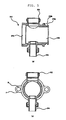
- FIG. 3 is a side elevation view of FIG. 2
- FIGS. 4 to 6 are example views illustrating distributor pipes of the hot water distributor according to the invention.
- the hot water distributor of the invention includes plate-shaped support brackets 100, which are fixed in a mounting place, fixing bolts 110 extending perpendicularly and fastened to the support brackets 100, A-type, B-type and C-type distributor pipes 200, 210 and 220, fixed by the fixing bolts 110, and warming pipes 300, which are connected to the A-type, B-type and C-type distributor pipes 200, 210 and 220.
- the mounting structure using the support brackets 100 is merely illustrative, but the hot water distributor can be directly fixed to the mounting place using a clamp, a band or the like, without the use of the support brackets.
- Each of the A-type, B-type and C-type distributor pipes 200, 210 and 220 can be provided with a flow rate valve 400 or an automatic temperature regulating valve 500 through a valve actuator 510.
- Fixing nuts 120 are engaged with the fixing bolts 110, thereby fixing the fixing bolts 110 to the support brackets 100.
- A-type, B-type and C-type distributor pipes 200, 210 and 220 are inserted into each other in a hermetically sealed state, and are fixed to the support brackets 100 using the fixing bolts 110 and the fixing nuts 120, thereby forming a single main distribution pipe, that is, a supply pipe S or a return pipe R.
- the supply pipe S and the return pipe R have the same structure, but are arranged in opposite directions so that they do not interfere with each other when connected to the warming pipes 300.
- the supply pipe S and the return pipe R are generally arranged in this structure because construction is convenient.
- the A-type, B-type and C-type distributor pipes 200, 210 and 220 have different lengths.
- the A-type distributor pipe 200 fixed to one of the support brackets 100 is the longest
- the C-type distributor pipe 220 fixed to the other one of the support brackets 100 is the second longest
- the B-type distributor pipe 210 interposed between the A-type and C-type distributor pipes 200 and 220 is the shortest.
- the distributor pipe 210 forms a plurality of zones in order to vary the length of the supply pipe S or the return pipe R.
- zone indicates the number of warming pipes 300 installed in the supply pipe S or the return pipe R, which is constructed by the connection of the A-type, second and C-type distributor pipes 200, 210 and 200'.
- zone is commonly called as, for example, “4 zones” and “5 zones,” and it can be understood that the design specification of the zone is standardized according to the number thereof.
- the A-type distributor pipe 200 has substantially circular second fixing flanges F at both ends in the horizontal diametrical direction of the A-type distributor pipe 200.
- a bolt hole B is formed in a respective one of the second fixing flanges F.
- the second fixing flanges F closely contact the outer circumference of the support brackets 100 in the configuration shown in FIG. 2 .
- Connectors 202 and 204 protrude from upper and lower portions of the A-type distributor pipe 200 in the direction crossing the second fixing flanges F. At least one of the automatic temperature regulating valve 500, the flow rate valve 400 and the warming pipe 300 can be connected to the connectors 202 and 204.
- a distributor pipe connector 206 is provided in a lateral portion of the A-type distributor pipe 200, which extends a shorter distance in the longitudinal direction, and a boiler connector 208 is provided in the opposite portion of the A-type distributor pipe 200, which extends a longer distance in the longitudinal direction.
- the B-type distributor pipe 210 can be inserted into the distributor pipe connector 206, and the boiler connector 208 can be connected to a boiler to supply or return warming water.
- the top end, where the connector 204 is formed, preferably protrudes higher than the inner circumference of the A-type distributor pipe 200.
- the top end of the connector 204 forms an opening/closing seat surface SF, which protrudes higher than the inner circumference of the A-type distributor pipe 200, which is the bottom surface WF where fluid is located. In this way, it is possible to minimize the malfunction of the automatic temperature regulating valve 500 or the flow rate valve 400 by foreign materials in the case of opening/closing thereof.
- the B-type distributor pipe 210 has a structure similar to that of the aforementioned A-type distributor pipe 200. While the A-type distributor pipe 200 is a structure for fixing the entire piping, the B-type distributor pipe 210 is a distributor pipe having a pure connecting function, by which the length of the pipes of the supply pipe S or the return pipe R, that is, the number of zones, can be adjusted.
- the B-type distributor pipe 210 should have a sealing structure capable of realizing a perfect hermetic seal.
- the B-type distributor pipe 210 also has connectors 212 and 214, which vertically protrude so as to be connected to the automatic temperature regulating valve 500, the flow rate valve 400 or the warming pipe 300.
- a distributor pipe connector 216 is formed at one end in the longitudinal direction, and a distributor pipe insert 218 is formed on the opposite end.
- annular main sealing groove 218a is formed to have a slightly downwardly recessed shape, slightly stepped from the front end.
- a step is vertically formed in the direction opposite the front end, spaced apart from the main sealing groove 218a, and a sub sealing groove 218b is recessed in the step, thereby forming a double sealing structure.
- a seal 600 such as an O-ring, as shown in FIG. 2 , is inserted into a respective one of the main sealing groove 218a and the sub sealing groove 218b.
- first fixing flanges F and bolt holes B are formed in opposing side portions of the B-type distributing pipe 210 in a diametrical direction, configured the same as those in the aforementioned A-type distributor pipe 200.
- a bushing 800 is inserted into the bolt hole B to remove inner play when the fixing bolt 110 is screwed into the bolt hole B. This can improve fixing force as well as suppress noise.
- the C-type distributor pipe 220 is fabricated to have the average length of the A-type distributor pipe 200 and the B-type distributor pipe 210, and acts to fix one end of the entire piping, like the A-type distributor pipe 200.
- the C-type distributor pipe 220 also has connectors 222 and 224, which vertically protrude for connection to the automatic temperature regulating valve 500, the flow rate valve 400 or the warming pipe 300.
- a boiler connector 226 is formed at one end in the longitudinal direction, and a distributor insert 228 is formed at the opposite end in the longitudinal direction.
- annular main sealing groove 228a is formed in a slightly downwardly recessed shape, slightly stepped from the front end.
- a step is vertically formed in the direction opposite the front end, spaced apart from the main sealing groove 228a, and a sub sealing groove 228b is recessed in the step, thereby forming a double sealing structure.
- second fixing flanges F and bolt holes B are formed in opposing side portions of the C-type distributing pipe 210 in a diametrical direction, that is, the direction crossing the connectors 222 and 224.
- the second fixing flanges F and bolt holes B are configured the same as those in the aforementioned A-type distributor pipe 200.
- the number of hot water distributors to be constructed is determined. For example, if it is determined that five (5) zone hot water distributors are to be constructed, as shown in the drawings, three identical B-type distributor pipes 210 are prepared, in addition to the A-type distributor pipe 200 and the C-type distributor pipe 220.
- the distributor pipes 200, 210 and 220 are connected sequentially.
- the A-type distributor pipe 200, the three B-type distributor pipes 210 and the C-type distributor pipe 220 are inserted into and assembled with each other sequentially in the order.
- the distributor insert 218 of the first one of the B-type distributor pipes 210 is inserted into the distributor pipe connector 206 of the A-type distributor pipe 200, with the sealings 600 inserted into the main sealing groove 218a and into the sub sealing groove 218b.
- the distributor insert 218 of the second one of the B-type distributor pipes 210 is inserted into the distributor connector 216 of the former distributor pipe 210 in the same fashion.
- the distributor pipe insert 228 of the C-type distributor pipe 220 is inserted into the distributor pipe connector 216 of the last one of the second distributor pipes 210.
- the fixing bolt 110 that is, a long bolt, is pushed into the bolt holes B of the first fixing flanges F of the A-type, B-type and C-type distributor pipes 200, 210 and 220, which are arranged in this position, so that all of the distributing pipes are engaged with the fixing bolt 110, and are thus assembled together.
- the pipe connector 208 of the A-type distributor pipe 200 and the boiler connector 226 of the C-type distributor pipe 220 are brought in close contact with the inner surface of the support brackets 100, fixing bolts 110 are inserted through the support brackets 100, and the fixing bolts 110 are tightened with the fixing nuts 120 from outside.
- the A-type, B-type and C-type distributor pipes 200, 210 and 220 are strongly and closely pressed to each other, and the sealings 600 form a perfect hermetic seal, thereby forming one main distribution pipe.
- one supply pipe S or one return pipe R is constructed.
- the automatic temperature regulating valves 500, the flow rate valves 400, or the warming pipe 300 are connected, in necessary numbers, to necessary places of the connectors 202, 212, 222, 204, 214 and 224 of the A-type, B-type and C-type distributor pipes 200, 210 and 220, thereby forming one hot water distributor.
- valve actuator 510 can be provided to embody the automatic temperature regulating valves 500.
- the length of the piping can be freely adjusted by suitably combining the A-type, B-type and C-type distributor pipes 200, 210 and 220, and thus the convenience of construction is maximized.
- the first distributor pipe 200' and the third distributor pipe 220' can be embodied by modifying the A-type distributor pipe 200 and the C-type distributor pipe 220 so that the hot water distributors can maintain the integrally combined state.
- the B-type distributor pipe 210 can be used as a linkage pipe without modification between the first distributor pipe 200' and the third distributor pipe 220'. Therefore, the B-type distributor pipe 210 in this embodiment is called as the second distributor pipe 210 for the purpose of distinguishing different embodiment of the invention. And, explanations about the second (B-type) distributor pipe 210 are omitted since its composition and function is the same as explained with regard to the Figs. 1 to 6 .
- FIGS. 7 to 12 are example views of the first distributor pipe 200' according to a second embodiment of the invention, in which FIG. 7 is a partially broken front elevation view illustrating a hot water distributor according to the second embodiment, FIG. 8 is a front elevation view of the first distributor pipe of the hot water distributor shown in FIG. 7 , seen from the pipe connector, FIG. 9 is a perspective view of a hexagonal nut for fixing the first distributor pipe and the third distributor pipe with a fixing bolt, FIG. 10 is a perspective view of a cap nut for fixing the hot water distributor to the support brackets, FIG. 11 is a front elevation view illustrating the hexagonal nut engaged with the first distributor pipe, and FIG. 12 is a front elevation view illustrating the hexagonal nut engaged with the third distributor pipe.
- the first and third distributor pipes 200' and 220' of this embodiment have the same overall structure as the A-type and C-type distributor pipes 200 and 220, shown in FIGS. 2 to 6 .
- the hexagonal nut insert hole B' is formed in the second fixing flange F', and the protrusion 130a at one end of the hexagonal nut 130 (see FIG. 9 ) is fixedly inserted into the hexagonal nut insert hole B'.
- the hexagonal nut hole 201 (see FIG. 12 ) is formed in the outer circumference of the hexagonal nut insert hole B' in the side of the pipe connector of the second fixing flange F'.
- the hexagonal nut hole 201 has a greater diameter than the hexagonal nut insert hole B', so that the outer circumference of the hexagonal nut 130 is inserted into and stored in the hexagonal nut hole 201.
- the hexagonal nut bolt hole B" is formed in the center of the hexagonal nut 130, and has inner threads for meshing with the fixing bolt 110 (see FIGS. 9 and 11 ).
- the hexagonal nuts 130 are stored in the hexagonal nut holes 201, and the protrusion 130b in the bottom of the hexagonal nut 130 is inserted into the hexagonal nut insert hole B'.
- the fixing bolts 110 are inserted through the first and second flanges of the first to third distributor pipes 200', 210 and 220', and the threads in the end of the fixing bolts 110 are screwed into the hexagonal bolt holes B". Then, the first to third distributor pipes 200', 210 and 220' can be fixedly and integrally combined together without being fixed to the support brackets.
- the cap nuts 120' are provided in the first and third distributor pipes 200' and 220'.
- a respective cap nut 120' meshes with the end of the fixing bolt 110, which protrudes from the hexagonal hole 130b of the hexagonal nut 130, into which a hexagonal wrench will be inserted.
- the cap nuts 120' are inserted into through holes in the support bracket 100, and mesh with the fixing bolts 110, which protrude from the inside of the hexagonal holes 130b of the hexagonal nuts 130, thereby fixing the hot water distributor having the first to third distributor pipes 200', 210 and 220' to the support brackets 100.
- This feature of this embodiment is also different from the A-type and C-type distributor pipes 200 and 220 of the hot water distributor shown in FIGS. 2 to 6 .
- the first and third distributor pipes 200' and 220' are also provided with connectors, like the A-type and C-type distributor pipes 200 and 220.
- the connectors are fixedly connected to at least one of the automatic temperature regulating valve, the flow rate valve and the boiler pipe.
- the connectors of the first and third distributor pipes have the top end protruding higher than the inner circumference of the first and third distributor pipes.
- main sealing grooves are recessed in the outer circumference of the inserted part, spaced apart from the front end.
- Sub sealing grooves are formed in the step, spaced apart from the main sealing grooves.
- a seal (O-ring) is inserted into a respective one of the main and sub sealing grooves.
- a bushing is inserted in the bolt hole of the first and second fixing flanges.
- the hot water distributor of the invention maintains an integrally assembled and fixed shape, even if separated from the support brackets 100. Hence, it is possible to test the internal pressure or hermetic seal in the state in which only the hot water distributor is fixedly assembled together, without being fixed to the support brackets 100. Also, in the case of separating the hot water distributor from the support brackets 100 for maintenance, even if the cap nut 120' is detached, the hot water distributor maintains a fixed state due to the fixing bolt 110 and the hexagonal nut 130, without the separation of the zone distributor pipe. Therefore, it is possible to protect the hot water distributor from leakage and breakage even in the situation where an unskilled person disassembles the hot water distributor.
- the length of the body can be freely varied according to the size of areas to be warmed.
- inventory control is easy, a perfect seal is obtained, and unnecessary operations can be avoided in the assembling operation, thereby improving working efficiency.
- the hot water distributor of the invention can maintain the integrally assembled state.
- the hot water distributor can maintain the integrally assembled state.
Landscapes
- Engineering & Computer Science (AREA)
- Physics & Mathematics (AREA)
- Thermal Sciences (AREA)
- Chemical & Material Sciences (AREA)
- Combustion & Propulsion (AREA)
- Mechanical Engineering (AREA)
- General Engineering & Computer Science (AREA)
- Branch Pipes, Bends, And The Like (AREA)
- Valve Housings (AREA)
- Domestic Plumbing Installations (AREA)
- Heat-Pump Type And Storage Water Heaters (AREA)
- Multiple-Way Valves (AREA)
Applications Claiming Priority (1)
| Application Number | Priority Date | Filing Date | Title |
|---|---|---|---|
| KR1020070069662A KR100915166B1 (ko) | 2007-07-11 | 2007-07-11 | 단위 조립형 구별 분리형 온수분배기 |
Publications (2)
| Publication Number | Publication Date |
|---|---|
| EP2014991A2 true EP2014991A2 (fr) | 2009-01-14 |
| EP2014991A3 EP2014991A3 (fr) | 2009-05-13 |
Family
ID=38543797
Family Applications (1)
| Application Number | Title | Priority Date | Filing Date |
|---|---|---|---|
| EP07017510A Withdrawn EP2014991A3 (fr) | 2007-07-11 | 2007-09-06 | Distributeur d'eau chaude assemblé en une unité et pouvant se diviser par zones |
Country Status (3)
| Country | Link |
|---|---|
| EP (1) | EP2014991A3 (fr) |
| KR (1) | KR100915166B1 (fr) |
| CN (1) | CN101344277B (fr) |
Cited By (3)
| Publication number | Priority date | Publication date | Assignee | Title |
|---|---|---|---|---|
| EP2246604A1 (fr) * | 2009-04-30 | 2010-11-03 | Staubli Faverges | Nourrice de distribution ou de collecte de fluide et installation de moulage comprenant une telle nourrice |
| IT201800003450A1 (it) * | 2018-03-12 | 2019-09-12 | Enolgas Bonomi S P A | Collettore di distribuzione |
| EP3598008A1 (fr) * | 2018-07-16 | 2020-01-22 | REHAU AG + Co | Système de montage de distributeur de fluide pour un système de chauffage et / ou de refroidissement |
Families Citing this family (7)
| Publication number | Priority date | Publication date | Assignee | Title |
|---|---|---|---|---|
| KR101302325B1 (ko) * | 2008-07-21 | 2013-08-30 | 홍석기 | 난방 분배기용 분배관 |
| KR100986259B1 (ko) * | 2009-12-17 | 2010-10-07 | (주)상신 | 밸브 일체형 구별 분리형 온수분배기 |
| CN106439346B (zh) * | 2016-10-14 | 2020-03-27 | 深圳市飞托克实业有限公司 | 一种气源分配器 |
| CN106524272B (zh) * | 2016-10-27 | 2019-04-26 | 华北科技学院 | 一种地暖专用不锈钢分水器 |
| DE102018108562A1 (de) * | 2018-04-11 | 2019-10-17 | Johnson Electric Germany GmbH & Co. KG | Stellantrieb, Heizkreisverteiler und Verfahren zur Montage des Stellantriebes in einem solchen Heizkreisverteiler |
| CN210623888U (zh) * | 2019-10-12 | 2020-05-26 | 浙江鑫帆暖通智控股份有限公司 | 一种分集水器 |
| CN111927983A (zh) * | 2020-07-24 | 2020-11-13 | 上海紫新姗实业有限公司 | 一种地暖分水器支架 |
Family Cites Families (6)
| Publication number | Priority date | Publication date | Assignee | Title |
|---|---|---|---|---|
| KR950004277U (ko) * | 1993-07-19 | 1995-02-17 | 신현완 | 분배기 |
| KR100284052B1 (ko) * | 1998-08-12 | 2001-04-02 | 강용주 | 난방용수분배기 |
| CN2434614Y (zh) * | 2000-07-04 | 2001-06-13 | 尹昌铉 | 热水分配装置 |
| KR200394385Y1 (ko) * | 2005-06-16 | 2005-08-31 | 신화정공 주식회사 | 밸브 일체형 조립식 헤더가 구비된 난방용 온수 분배기 |
| KR200417942Y1 (ko) * | 2005-12-30 | 2006-06-07 | (주)상신 | 구별 분리형 온수분배기 |
| KR100727019B1 (ko) * | 2005-12-30 | 2007-06-12 | (주)상신 | 구별 분리형 온수분배기 |
-
2007
- 2007-07-11 KR KR1020070069662A patent/KR100915166B1/ko active Active
- 2007-09-06 EP EP07017510A patent/EP2014991A3/fr not_active Withdrawn
- 2007-09-20 CN CN2007101537625A patent/CN101344277B/zh not_active Expired - Fee Related
Non-Patent Citations (1)
| Title |
|---|
| None |
Cited By (6)
| Publication number | Priority date | Publication date | Assignee | Title |
|---|---|---|---|---|
| EP2246604A1 (fr) * | 2009-04-30 | 2010-11-03 | Staubli Faverges | Nourrice de distribution ou de collecte de fluide et installation de moulage comprenant une telle nourrice |
| FR2945101A1 (fr) * | 2009-04-30 | 2010-11-05 | Staubli Sa Ets | Nourrice de distribution ou de collecte de fluide et installation de moulage comprenant une telle nourrice |
| US8356632B2 (en) | 2009-04-30 | 2013-01-22 | Staubli Faverges | Manifold for distributing or for collecting fluid, and a molding installation including such a manifold |
| IT201800003450A1 (it) * | 2018-03-12 | 2019-09-12 | Enolgas Bonomi S P A | Collettore di distribuzione |
| EP3540317A1 (fr) * | 2018-03-12 | 2019-09-18 | Enolgas Bonomi S.p.A. | Collecteur |
| EP3598008A1 (fr) * | 2018-07-16 | 2020-01-22 | REHAU AG + Co | Système de montage de distributeur de fluide pour un système de chauffage et / ou de refroidissement |
Also Published As
| Publication number | Publication date |
|---|---|
| CN101344277B (zh) | 2012-07-18 |
| KR100915166B1 (ko) | 2009-09-03 |
| CN101344277A (zh) | 2009-01-14 |
| EP2014991A3 (fr) | 2009-05-13 |
| KR20090006380A (ko) | 2009-01-15 |
Similar Documents
| Publication | Publication Date | Title |
|---|---|---|
| EP2014991A2 (fr) | Distributeur d'eau chaude assemblé en une unité et pouvant se diviser par zones | |
| TWI388753B (zh) | 流體控制裝置 | |
| EP0993584B1 (fr) | Collecteur de distribution pour eau potable et chauffage local a l'eau chaude | |
| CN105299347A (zh) | 制冷剂管的连接结构 | |
| TWI387696B (zh) | 流體控制裝置及其組立方法 | |
| KR20050112960A (ko) | 배관 고정 장치 | |
| US11175063B2 (en) | Switching device for multi-split air conditioner and multi-split air conditioner having same | |
| US20100037629A1 (en) | Crimped orifice for flare fitting | |
| CN102359632A (zh) | 节流阀 | |
| KR200417942Y1 (ko) | 구별 분리형 온수분배기 | |
| KR100727019B1 (ko) | 구별 분리형 온수분배기 | |
| US6907905B2 (en) | Manifold of a plastics material for hot-water heating system and the like | |
| CA2568706C (fr) | Robinet sans brides a action directe | |
| CN110506190B (zh) | 变压器散热器 | |
| KR101975449B1 (ko) | 분배기와 밸브의 체결구조 | |
| TWI850437B (zh) | 減壓閥、用於減壓閥之上層隔膜追加單元 | |
| US20240410660A1 (en) | Support component and heat exchanger support obtained from an assembly of such support components | |
| JP2011099636A (ja) | 開閉弁 | |
| KR100779248B1 (ko) | 확장형 멀티웨이체크밸브 | |
| KR100775390B1 (ko) | 난방용 온수분배기 | |
| KR930005041Y1 (ko) | 난방용 온수분재 장치 | |
| KR100950219B1 (ko) | 콤팩트한 연결구조를 제공하는 파이프 어셈블리 | |
| RU2798403C2 (ru) | Головка для тепловых радиаторов и способ изготовления такой головки | |
| KR200438741Y1 (ko) | 에어컨 설치배관용 플러그 | |
| KR200394531Y1 (ko) | 디퓨져 조립체 |
Legal Events
| Date | Code | Title | Description |
|---|---|---|---|
| PUAI | Public reference made under article 153(3) epc to a published international application that has entered the european phase |
Free format text: ORIGINAL CODE: 0009012 |
|
| 17P | Request for examination filed |
Effective date: 20070906 |
|
| AK | Designated contracting states |
Kind code of ref document: A2 Designated state(s): AT BE BG CH CY CZ DE DK EE ES FI FR GB GR HU IE IS IT LI LT LU LV MC MT NL PL PT RO SE SI SK TR |
|
| AX | Request for extension of the european patent |
Extension state: AL BA HR MK RS |
|
| PUAL | Search report despatched |
Free format text: ORIGINAL CODE: 0009013 |
|
| AK | Designated contracting states |
Kind code of ref document: A3 Designated state(s): AT BE BG CH CY CZ DE DK EE ES FI FR GB GR HU IE IS IT LI LT LU LV MC MT NL PL PT RO SE SI SK TR |
|
| AX | Request for extension of the european patent |
Extension state: AL BA HR MK RS |
|
| 17Q | First examination report despatched |
Effective date: 20090710 |
|
| AKX | Designation fees paid |
Designated state(s): AT BE BG CH CY CZ DE DK EE ES FI FR GB GR HU IE IS IT LI LT LU LV MC MT NL PL PT RO SE SI SK TR |
|
| GRAP | Despatch of communication of intention to grant a patent |
Free format text: ORIGINAL CODE: EPIDOSNIGR1 |
|
| STAA | Information on the status of an ep patent application or granted ep patent |
Free format text: STATUS: THE APPLICATION IS DEEMED TO BE WITHDRAWN |
|
| 18D | Application deemed to be withdrawn |
Effective date: 20110401 |