EP2015080A2 - Tachygraphe avec dispositif d'impression - Google Patents
Tachygraphe avec dispositif d'impression Download PDFInfo
- Publication number
- EP2015080A2 EP2015080A2 EP08103969A EP08103969A EP2015080A2 EP 2015080 A2 EP2015080 A2 EP 2015080A2 EP 08103969 A EP08103969 A EP 08103969A EP 08103969 A EP08103969 A EP 08103969A EP 2015080 A2 EP2015080 A2 EP 2015080A2
- Authority
- EP
- European Patent Office
- Prior art keywords
- tachograph according
- tachograph
- receiving chamber
- printing material
- rotary drive
- Prior art date
- Legal status (The legal status is an assumption and is not a legal conclusion. Google has not performed a legal analysis and makes no representation as to the accuracy of the status listed.)
- Withdrawn
Links
Images



Classifications
-
- G—PHYSICS
- G01—MEASURING; TESTING
- G01P—MEASURING LINEAR OR ANGULAR SPEED, ACCELERATION, DECELERATION, OR SHOCK; INDICATING PRESENCE, ABSENCE, OR DIRECTION, OF MOVEMENT
- G01P1/00—Details of instruments
- G01P1/12—Recording devices
-
- B—PERFORMING OPERATIONS; TRANSPORTING
- B41—PRINTING; LINING MACHINES; TYPEWRITERS; STAMPS
- B41J—TYPEWRITERS; SELECTIVE PRINTING MECHANISMS, i.e. MECHANISMS PRINTING OTHERWISE THAN FROM A FORME; CORRECTION OF TYPOGRAPHICAL ERRORS
- B41J15/00—Devices or arrangements of selective printing mechanisms, e.g. ink-jet printers or thermal printers, specially adapted for supporting or handling copy material in continuous form, e.g. webs
- B41J15/04—Supporting, feeding, or guiding devices; Mountings for web rolls or spindles
-
- B—PERFORMING OPERATIONS; TRANSPORTING
- B41—PRINTING; LINING MACHINES; TYPEWRITERS; STAMPS
- B41J—TYPEWRITERS; SELECTIVE PRINTING MECHANISMS, i.e. MECHANISMS PRINTING OTHERWISE THAN FROM A FORME; CORRECTION OF TYPOGRAPHICAL ERRORS
- B41J15/00—Devices or arrangements of selective printing mechanisms, e.g. ink-jet printers or thermal printers, specially adapted for supporting or handling copy material in continuous form, e.g. webs
- B41J15/04—Supporting, feeding, or guiding devices; Mountings for web rolls or spindles
- B41J15/042—Supporting, feeding, or guiding devices; Mountings for web rolls or spindles for loading rolled-up continuous copy material into printers, e.g. for replacing a used-up paper roll; Point-of-sale printers with openable casings allowing access to the rolled-up continuous copy material
-
- G—PHYSICS
- G01—MEASURING; TESTING
- G01D—MEASURING NOT SPECIALLY ADAPTED FOR A SPECIFIC VARIABLE; ARRANGEMENTS FOR MEASURING TWO OR MORE VARIABLES NOT COVERED IN A SINGLE OTHER SUBCLASS; TARIFF METERING APPARATUS; MEASURING OR TESTING NOT OTHERWISE PROVIDED FOR
- G01D15/00—Component parts of recorders for measuring arrangements not specially adapted for a specific variable
- G01D15/28—Holding means for recording surfaces; Guiding means for recording surfaces; Exchanging means for recording surfaces
-
- G—PHYSICS
- G01—MEASURING; TESTING
- G01D—MEASURING NOT SPECIALLY ADAPTED FOR A SPECIFIC VARIABLE; ARRANGEMENTS FOR MEASURING TWO OR MORE VARIABLES NOT COVERED IN A SINGLE OTHER SUBCLASS; TARIFF METERING APPARATUS; MEASURING OR TESTING NOT OTHERWISE PROVIDED FOR
- G01D15/00—Component parts of recorders for measuring arrangements not specially adapted for a specific variable
- G01D15/34—Recording surfaces
- G01D15/347—Strip or Tape
-
- G—PHYSICS
- G01—MEASURING; TESTING
- G01P—MEASURING LINEAR OR ANGULAR SPEED, ACCELERATION, DECELERATION, OR SHOCK; INDICATING PRESENCE, ABSENCE, OR DIRECTION, OF MOVEMENT
- G01P1/00—Details of instruments
- G01P1/12—Recording devices
- G01P1/14—Recording devices for permanent recording
Definitions
- the invention relates to a tachograph with a housing in which a printing device and a receiving chamber for a roll of printable by the printing device belt-like printing material is arranged, wherein the roller has a central roller core, which is freely rotatably mounted on an axis, with a the printing area of the printing device in parallel opposite, about a roll axis rotatably driven by a rotary drive transport roller through which in a transport plane past the printing area be conveyed print material in contact with the printing area acted upon and can be conveyed past the printing area.
- a sharp tear-off edge is arranged, over which the printed printing material is pulled and thus separated.
- the object of the invention is therefore to provide a tachograph of the type mentioned, which has a more cost-effective structure.
- a detachable from the housing unit can be arranged, which has a bearing block on which arranged the role of the printing material supporting axis and the transport roller is rotatably mounted, wherein the transport roller in the installed position of the unit is coupled in the receiving chamber with the rotary drive.
- the entire assembly including transport roller is removed from the receiving chamber and a new, a full roll of printed material contained unit used.
- the assembly whose print material is used up, can either be returned to the printing material manufacturer for reprinting with printing material or recycled.
- the parts of the components of the assembly made of plastic.
- the receiving chamber can have an insertion opening that can be opened or opened to an operator side of the tachograph.
- the printing device and the receiving chamber are arranged in a drawer-like carrier which can be moved out of the receiving shaft of the housing to the operator side, then the loading opening can be arranged on the upper side of the carrier and be closed by the housing when the carrier is in the operating position.
- the loading opening is closed by a lid.
- the cover may be a pivotable about a pivot axis closure flap, which is thus arranged on the housing.
- the pivot axis extends along an edge of the loading opening.
- the cover is a component of the assembly and thus also exchanged in an exchange of the assembly.
- the assembly can be locked by means of a releasable locking connection in the mounting position of the unit in the receiving chamber.
- the structural unit can have one or more latching arms which engage behind corresponding latching cams of the housing in the installation position of the structural unit.
- the outer free end of the ribbon-like printing material can be guided through a printing material slot which opens out to the operator side.
- the printing material slot may be formed in the lid, through which the loading opening is closable.
- a drive wheel is arranged coaxially on the transport roller, which in the installation position of the module is in direct or indirect drive engagement with the rotary drive, then with the onset of a new module a coupling of the transport roller to the rotary drive is forced.
- the drive wheel may be a Zahnantriebsrad and / or the transmission may be a gear transmission.
- the rotary drive is arranged on the housing and can be coupled in positioning the assembly in the receiving chamber with the drive wheel or the transmission, wherein preferably the rotary drive can be an electric motor ,
- the rotary drive can also be arranged on the structural unit and have connection contacts which can be contacted with positioning of the structural unit in the receiving chamber with current supply contacts arranged on the housing.
- This training does not require a rotary drive, which must be designed for the entire life of the vehicle, but it is sufficient low-cost rotary drive, since its function must be ensured only for the consumption of a roll of printing material.
- a rotary drive which must be designed for the entire life of the vehicle, but it is sufficient low-cost rotary drive, since its function must be ensured only for the consumption of a roll of printing material.
- a particularly simply constructed and cost-effective rotary drive is that the rotary drive is a piezomotor.
- the piezomotor may have a resiliently arranged on the assembly resonator on which a piezoelectric device is arranged and which is in contact with a contact area on the drive wheel, wherein during operation of the piezoelectric motor of the contact region of the resonator an elliptical or linear oscillation is executable.
- the bearing block can consist of two side parts, which are connected to one another via one or more trusses.
- the axis carrying the roll of the printing material can form a traverse.
- a simple structure results further when the transport roller extends between the two side parts and is rotatably mounted with their end portions in bearing openings of the side parts.
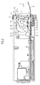
- the tachograph shown in the figures has a housing 1 with a rectangular cross-section in DIN radio format.
- the housing 1 is inserted into a corresponding shaft in the instrument panel 2 of a motor vehicle and covered at its side facing the operator side insertion opening 3 of a panel frame 4.
- an insertion slot 5 is formed in the frame 4, in which a chip card is inserted, the memory chips for storing data such as driver, vehicle, ride and working time data contains.
- the loading opening 3 is closed by a lid 6 and 6 ', which in the embodiment of FIG. 2 is mounted to a along the lower edge region of the insertion opening 3 horizontally extending flap axis 7 pivotally.
- a receiving chamber 8 is formed, which opens via the loading opening 3 to the operator side to the outside.
- the receiving chamber 8 In the receiving chamber 8 is a unit 9, 9 'inserted guided from the operator side and locked in its operating position.
- the assembly 9, 9 ' has two spaced-apart plate-like side parts 10, which are connected to each other via a transversely to the insertion direction 11 of the assembly 9, 9' in the receiving chamber 8 extending axis 12.
- the outer free end 15 of the belt-like printing material 14 is guided by a printing material slot 16, 16 'to the operator side to the outside.
- the printing material slot 16 between the flap axis 7 opposite free edge of the lid 6 and the corresponding edge of the mounting hole 3 is formed.
- the printing material slot 16 'in the upper end of the lid 6' is formed.
- a transport roller 18 is arranged between the side parts 10 and rotatably supported with axle journals 19 at their end regions in bearing openings of the side parts 10.
- the free end 15 of the printing material 14 is guided from the roller 13 via the transport roller 18 and the support strip 17 through the printing material slot 16, 16 'to the outside.
- the printing material 14 is held in abutment against a thermal printing bar, not shown, of a printing device, which is arranged extending transversely to the insertion direction 11 in the housing 1 and through which the printing material 14 can be printed.
- the transport roller 18 is rotatably driven and thereby the printing material 14 against the insertion direction 11 to the operator side to be conveyed.
- the transport roller 18 is rotatably driven via the transmission and the coupled into the transmission gear drive wheel 20.
- the cover 6 ' is integrally formed with the assembly 9' via a carrier part 25 extending counter to the insertion direction 11 so that the assembly opening 3 is simultaneously opened when the assembly 9 'is withdrawn.
- unit 9 is like the units 9 and 9 'inserted into the receiving chamber 8 guided from the operator side and locked in its operating position.
- the assembly 9 is built up to the drive as the assembly 9 and also has two spaced-apart plate-like side parts 10, which are connected to each other via a transversely to the insertion direction 11 of the assembly 9" in the receiving chamber 8 extending axis 12.
- the outer free end 15 of the belt-like printing material 14 is guided through a printing material slot to the operator side to the outside.
- a drive wheel 26 is arranged on the axle journal 19 of the transport roller 18, the radial circumferential surface 27 may have a roughness.
- a rod-like resonator 28 of a piezo motor 29 On the mantle surface 27 is a rod-like resonator 28 of a piezo motor 29 with its one end 30 with frictional contact in abutment, wherein the longitudinal extent of the resonator 28 does not intersect the axis of rotation of the drive wheel 26.
- the friction partners of lateral surface 27 and end 30 of the resonator 28 must be matched to one another in such a way that a movement of the drive wheel 26 can be generated.
- the resonator 28 With its second end 32, the resonator 28 is so resiliently connected to the one side part 10 that it is in contact with the drive wheel 26 with its first end 30.
- the piezoelectric motor 29 When the piezoelectric motor 29 is acted upon by the exciter signal, the resonator 28 is excited by the piezoelectric component 33 in such a way that its end 30 having a contact region performs an elliptical oscillation. As a result, the drive wheel 26 is set into a rotational movement via the first end 30 and the printing material is conveyed through a printing material slot.
Landscapes
- Physics & Mathematics (AREA)
- General Physics & Mathematics (AREA)
- Time Recorders, Dirve Recorders, Access Control (AREA)
- Pile Receivers (AREA)
- Accessory Devices And Overall Control Thereof (AREA)
Applications Claiming Priority (2)
| Application Number | Priority Date | Filing Date | Title |
|---|---|---|---|
| DE102007027395 | 2007-06-11 | ||
| DE102008007371A DE102008007371A1 (de) | 2007-06-11 | 2008-02-01 | Fahrtschreiber |
Publications (2)
| Publication Number | Publication Date |
|---|---|
| EP2015080A2 true EP2015080A2 (fr) | 2009-01-14 |
| EP2015080A3 EP2015080A3 (fr) | 2009-02-25 |
Family
ID=39986325
Family Applications (1)
| Application Number | Title | Priority Date | Filing Date |
|---|---|---|---|
| EP08103969A Withdrawn EP2015080A3 (fr) | 2007-06-11 | 2008-05-15 | Tachygraphe avec dispositif d'impression |
Country Status (3)
| Country | Link |
|---|---|
| EP (1) | EP2015080A3 (fr) |
| BR (1) | BRPI0801685A2 (fr) |
| DE (1) | DE102008007371A1 (fr) |
Families Citing this family (1)
| Publication number | Priority date | Publication date | Assignee | Title |
|---|---|---|---|---|
| DE102009058075A1 (de) * | 2009-12-14 | 2011-06-16 | Continental Automotive Gmbh | Fahrtschreiber |
Citations (8)
| Publication number | Priority date | Publication date | Assignee | Title |
|---|---|---|---|---|
| US2341118A (en) | 1939-06-14 | 1944-02-08 | Rodanet Charles Hilaire Henri | Vehicle speed recorder |
| DE2655495A1 (de) | 1976-12-08 | 1978-06-15 | Medronik Systemtechnik Gmbh | Schreiber zur aufzeichnung von messdaten |
| DE3833342A1 (de) | 1988-09-30 | 1990-04-05 | Siemens Ag | Piezomotor |
| JPH0373707A (ja) | 1989-08-14 | 1991-03-28 | Ricoh Co Ltd | 駆動機構 |
| EP0655608A1 (fr) | 1993-11-18 | 1995-05-31 | MANNESMANN Aktiengesellschaft | Système d'entraînement pour un enregistreur de diagramme |
| EP0978887A2 (fr) | 1998-08-07 | 2000-02-09 | Seiko Instruments Inc. | Moteur à ultrasons et appareil électronique équipé d'un moteur à ultrasons |
| DE10046356A1 (de) | 2000-09-19 | 2001-10-04 | Agfa Gevaert Ag | Vorrichtung zum Antrieb einer Printwalze zum Transport von zu belichtendem oder zu bedruckendem Material |
| EP1575000A1 (fr) | 2004-03-02 | 2005-09-14 | Delphi Technologies, Inc. | Tachygraphe avec imprimante échangeable |
Family Cites Families (2)
| Publication number | Priority date | Publication date | Assignee | Title |
|---|---|---|---|---|
| DE2923415A1 (de) * | 1979-06-09 | 1980-12-11 | Eckardt Ag | Papiertransportwerk fuer schreibgeraete oder registriergeraete |
| DE29920901U1 (de) * | 1999-11-27 | 2000-01-13 | Mannesmann VDO AG, 60388 Frankfurt | Fahrtschreiber mit einer Druckvorrichtung |
-
2008
- 2008-02-01 DE DE102008007371A patent/DE102008007371A1/de not_active Withdrawn
- 2008-05-15 EP EP08103969A patent/EP2015080A3/fr not_active Withdrawn
- 2008-06-11 BR BRPI0801685 patent/BRPI0801685A2/pt not_active IP Right Cessation
Patent Citations (8)
| Publication number | Priority date | Publication date | Assignee | Title |
|---|---|---|---|---|
| US2341118A (en) | 1939-06-14 | 1944-02-08 | Rodanet Charles Hilaire Henri | Vehicle speed recorder |
| DE2655495A1 (de) | 1976-12-08 | 1978-06-15 | Medronik Systemtechnik Gmbh | Schreiber zur aufzeichnung von messdaten |
| DE3833342A1 (de) | 1988-09-30 | 1990-04-05 | Siemens Ag | Piezomotor |
| JPH0373707A (ja) | 1989-08-14 | 1991-03-28 | Ricoh Co Ltd | 駆動機構 |
| EP0655608A1 (fr) | 1993-11-18 | 1995-05-31 | MANNESMANN Aktiengesellschaft | Système d'entraînement pour un enregistreur de diagramme |
| EP0978887A2 (fr) | 1998-08-07 | 2000-02-09 | Seiko Instruments Inc. | Moteur à ultrasons et appareil électronique équipé d'un moteur à ultrasons |
| DE10046356A1 (de) | 2000-09-19 | 2001-10-04 | Agfa Gevaert Ag | Vorrichtung zum Antrieb einer Printwalze zum Transport von zu belichtendem oder zu bedruckendem Material |
| EP1575000A1 (fr) | 2004-03-02 | 2005-09-14 | Delphi Technologies, Inc. | Tachygraphe avec imprimante échangeable |
Also Published As
| Publication number | Publication date |
|---|---|
| DE102008007371A1 (de) | 2008-12-18 |
| BRPI0801685A2 (pt) | 2009-01-27 |
| EP2015080A3 (fr) | 2009-02-25 |
Similar Documents
| Publication | Publication Date | Title |
|---|---|---|
| DE4008541C1 (fr) | ||
| EP1103928B1 (fr) | Tachygraphe avec un dispositif d'impression | |
| DE69106946T2 (de) | Thermozeilendrucker. | |
| EP0150360B1 (fr) | Appareil d'enregistrement sur papier à écriture directe | |
| DE10215122B4 (de) | Fahrtschreiber mit einem quaderförmigen Gehäuse und einer Druckvorrichtung | |
| DE69918792T2 (de) | Kassette für photoempfindliches Band für einen elektrophotographischen Drucker, Gerät zum wechseln eines photoempfindliches Bandes das diese benutzt und Verfahren dafür | |
| EP1103927A2 (fr) | Tachygraphe avec un boítier plat et encastrable | |
| DE102008007371A1 (de) | Fahrtschreiber | |
| EP1356434B1 (fr) | Chronotachygraphe comportant un boitier parallelepipedique et un dispositif d'impression | |
| DE1031035B (de) | Vorrichtung zum Anzeigen und Registrieren der Fahrgeschwindigkeit und der Wegstrecke von Kraftfahrzeugen | |
| DE202011108254U1 (de) | Anordnung zum Bedrucken streifenförmiger Druckträger | |
| DE2233095B2 (de) | Transportvorrichtung für an den Seitenrändern mit Transportlöchern versehene Papierbahnen in einem Druckwerk einer Buchungsmaschine, Datenverarbeitungsanlage od.dgl | |
| DE69111564T2 (de) | Sperrvorrichtung für abnehmbare Frankiermaschine. | |
| EP0899676B1 (fr) | Réceptacle de faible épaisseur pour cartes de données | |
| DE60004735T2 (de) | Drucker mit Antrieb durch einen Motor, sowohl für Blattvorschub, als auch Blattschneidemechanismus | |
| EP1017013B1 (fr) | Dispositif de verrouillage pour un appareil de lecture/écriture de cartes de données | |
| DE69412783T2 (de) | Drucker mit multifunktionalem Papiermanipulationssystem | |
| EP2084354B1 (fr) | Serrure de porte, en particulier serrure de portière de véhicule automobile | |
| EP1643456B1 (fr) | Compartiment à cassettes avec détection de l'état pour une machine à affranchir | |
| DE69406765T2 (de) | Seriendrucker mit Papierschnipselbeseitiger | |
| DE2621370C3 (de) | Reinigungsanlage für Kraftfahrzeugscheiben | |
| DE2438068C3 (de) | Registriereinrichtung | |
| DE102011100508B4 (de) | Filtervorrichtung, insbesondere für Süßwasser- und Seewasserbecken | |
| EP1575000A1 (fr) | Tachygraphe avec imprimante échangeable | |
| DE69102831T2 (de) | Gehäusestruktur für eine Bildübertragungsvorrichtung. |
Legal Events
| Date | Code | Title | Description |
|---|---|---|---|
| PUAI | Public reference made under article 153(3) epc to a published international application that has entered the european phase |
Free format text: ORIGINAL CODE: 0009012 |
|
| PUAI | Public reference made under article 153(3) epc to a published international application that has entered the european phase |
Free format text: ORIGINAL CODE: 0009012 |
|
| AK | Designated contracting states |
Kind code of ref document: A2 Designated state(s): AT BE BG CH CY CZ DE DK EE ES FI FR GB GR HR HU IE IS IT LI LT LU LV MC MT NL NO PL PT RO SE SI SK TR |
|
| AX | Request for extension of the european patent |
Extension state: AL BA MK RS |
|
| PUAL | Search report despatched |
Free format text: ORIGINAL CODE: 0009013 |
|
| AK | Designated contracting states |
Kind code of ref document: A3 Designated state(s): AT BE BG CH CY CZ DE DK EE ES FI FR GB GR HR HU IE IS IT LI LT LU LV MC MT NL NO PL PT RO SE SI SK TR |
|
| AX | Request for extension of the european patent |
Extension state: AL BA MK RS |
|
| 17Q | First examination report despatched |
Effective date: 20090922 |
|
| AKX | Designation fees paid |
Designated state(s): DE FR SE |
|
| 17P | Request for examination filed |
Effective date: 20090825 |
|
| STAA | Information on the status of an ep patent application or granted ep patent |
Free format text: STATUS: THE APPLICATION IS DEEMED TO BE WITHDRAWN |
|
| 18D | Application deemed to be withdrawn |
Effective date: 20111201 |