EP2015131A1 - Dispositif d'affichage - Google Patents
Dispositif d'affichage Download PDFInfo
- Publication number
- EP2015131A1 EP2015131A1 EP08010733A EP08010733A EP2015131A1 EP 2015131 A1 EP2015131 A1 EP 2015131A1 EP 08010733 A EP08010733 A EP 08010733A EP 08010733 A EP08010733 A EP 08010733A EP 2015131 A1 EP2015131 A1 EP 2015131A1
- Authority
- EP
- European Patent Office
- Prior art keywords
- rib
- display device
- bezel
- display
- frame portion
- Prior art date
- Legal status (The legal status is an assumption and is not a legal conclusion. Google has not performed a legal analysis and makes no representation as to the accuracy of the status listed.)
- Granted
Links
Images


Classifications
-
- G—PHYSICS
- G02—OPTICS
- G02F—OPTICAL DEVICES OR ARRANGEMENTS FOR THE CONTROL OF LIGHT BY MODIFICATION OF THE OPTICAL PROPERTIES OF THE MEDIA OF THE ELEMENTS INVOLVED THEREIN; NON-LINEAR OPTICS; FREQUENCY-CHANGING OF LIGHT; OPTICAL LOGIC ELEMENTS; OPTICAL ANALOGUE/DIGITAL CONVERTERS
- G02F1/00—Devices or arrangements for the control of the intensity, colour, phase, polarisation or direction of light arriving from an independent light source, e.g. switching, gating or modulating; Non-linear optics
- G02F1/01—Devices or arrangements for the control of the intensity, colour, phase, polarisation or direction of light arriving from an independent light source, e.g. switching, gating or modulating; Non-linear optics for the control of the intensity, phase, polarisation or colour
- G02F1/13—Devices or arrangements for the control of the intensity, colour, phase, polarisation or direction of light arriving from an independent light source, e.g. switching, gating or modulating; Non-linear optics for the control of the intensity, phase, polarisation or colour based on liquid crystals, e.g. single liquid crystal display cells
- G02F1/133—Constructional arrangements; Operation of liquid crystal cells; Circuit arrangements
- G02F1/1333—Constructional arrangements; Manufacturing methods
- G02F1/133308—Support structures for LCD panels, e.g. frames or bezels
-
- G—PHYSICS
- G02—OPTICS
- G02F—OPTICAL DEVICES OR ARRANGEMENTS FOR THE CONTROL OF LIGHT BY MODIFICATION OF THE OPTICAL PROPERTIES OF THE MEDIA OF THE ELEMENTS INVOLVED THEREIN; NON-LINEAR OPTICS; FREQUENCY-CHANGING OF LIGHT; OPTICAL LOGIC ELEMENTS; OPTICAL ANALOGUE/DIGITAL CONVERTERS
- G02F1/00—Devices or arrangements for the control of the intensity, colour, phase, polarisation or direction of light arriving from an independent light source, e.g. switching, gating or modulating; Non-linear optics
- G02F1/01—Devices or arrangements for the control of the intensity, colour, phase, polarisation or direction of light arriving from an independent light source, e.g. switching, gating or modulating; Non-linear optics for the control of the intensity, phase, polarisation or colour
- G02F1/13—Devices or arrangements for the control of the intensity, colour, phase, polarisation or direction of light arriving from an independent light source, e.g. switching, gating or modulating; Non-linear optics for the control of the intensity, phase, polarisation or colour based on liquid crystals, e.g. single liquid crystal display cells
- G02F1/133—Constructional arrangements; Operation of liquid crystal cells; Circuit arrangements
- G02F1/1333—Constructional arrangements; Manufacturing methods
- G02F1/133308—Support structures for LCD panels, e.g. frames or bezels
- G02F1/133311—Environmental protection, e.g. against dust or humidity
-
- G—PHYSICS
- G02—OPTICS
- G02F—OPTICAL DEVICES OR ARRANGEMENTS FOR THE CONTROL OF LIGHT BY MODIFICATION OF THE OPTICAL PROPERTIES OF THE MEDIA OF THE ELEMENTS INVOLVED THEREIN; NON-LINEAR OPTICS; FREQUENCY-CHANGING OF LIGHT; OPTICAL LOGIC ELEMENTS; OPTICAL ANALOGUE/DIGITAL CONVERTERS
- G02F1/00—Devices or arrangements for the control of the intensity, colour, phase, polarisation or direction of light arriving from an independent light source, e.g. switching, gating or modulating; Non-linear optics
- G02F1/01—Devices or arrangements for the control of the intensity, colour, phase, polarisation or direction of light arriving from an independent light source, e.g. switching, gating or modulating; Non-linear optics for the control of the intensity, phase, polarisation or colour
- G02F1/13—Devices or arrangements for the control of the intensity, colour, phase, polarisation or direction of light arriving from an independent light source, e.g. switching, gating or modulating; Non-linear optics for the control of the intensity, phase, polarisation or colour based on liquid crystals, e.g. single liquid crystal display cells
- G02F1/133—Constructional arrangements; Operation of liquid crystal cells; Circuit arrangements
- G02F1/1333—Constructional arrangements; Manufacturing methods
- G02F1/133308—Support structures for LCD panels, e.g. frames or bezels
- G02F1/133322—Mechanical guidance or alignment of LCD panel support components
-
- G—PHYSICS
- G02—OPTICS
- G02F—OPTICAL DEVICES OR ARRANGEMENTS FOR THE CONTROL OF LIGHT BY MODIFICATION OF THE OPTICAL PROPERTIES OF THE MEDIA OF THE ELEMENTS INVOLVED THEREIN; NON-LINEAR OPTICS; FREQUENCY-CHANGING OF LIGHT; OPTICAL LOGIC ELEMENTS; OPTICAL ANALOGUE/DIGITAL CONVERTERS
- G02F2201/00—Constructional arrangements not provided for in groups G02F1/00 - G02F7/00
- G02F2201/46—Fixing elements
-
- G—PHYSICS
- G02—OPTICS
- G02F—OPTICAL DEVICES OR ARRANGEMENTS FOR THE CONTROL OF LIGHT BY MODIFICATION OF THE OPTICAL PROPERTIES OF THE MEDIA OF THE ELEMENTS INVOLVED THEREIN; NON-LINEAR OPTICS; FREQUENCY-CHANGING OF LIGHT; OPTICAL LOGIC ELEMENTS; OPTICAL ANALOGUE/DIGITAL CONVERTERS
- G02F2201/00—Constructional arrangements not provided for in groups G02F1/00 - G02F7/00
- G02F2201/50—Protective arrangements
- G02F2201/503—Arrangements improving the resistance to shock
Definitions
- the present invention generally relates to a display device. More specifically, the present invention relates to a display device having a display module housed in a cabinet.
- a conventional flat panel display device includes a front cabinet, a rear cabinet and a liquid crystal module.
- the front and rear cabinets mate together.
- the liquid crystal module is housed in the front and rear cabinets.
- the front cabinet has a front face opening, a support rib and a plurality of bosses.
- the support rib has a substantially square shape in a front elevational view and is integrally provided protruding from a rear face of the front cabinet along the front face opening of the front cabinet.
- the bosses are formed on the rear face of the front cabinet at locations spaced apart and outward of the support rib.
- the liquid crystal module has a liquid crystal panel, a bezel and a rear face member.
- the bezel is provided to an outer peripheral edge section of a front face of the liquid crystal panel.
- the rear face member protrudes outward from a rear face of the liquid crystal panel.
- the liquid crystal panel is inserted into the front cabinet so that the bezel contact with a flat face of the support rib with a planar contact.
- a plurality of screws are inserted into holes formed on the rear face member and threaded into center holes of the bosses.
- the liquid crystal panel is pressed against the flat face of the support rib with a pressing force. This fixes the liquid crystal panel at a specific location within the front and rear cabinets.
- the liquid crystal panel displays a video image by illuminating a liquid crystal cell provided to a front part of the liquid crystal panel from a rear side with a cold cathode fluorescent lamp (CCFL).
- CCFL cold cathode fluorescent lamp
- the flat face of the support rib contacts with the bezel of the liquid crystal module with a planar contact.
- the support rib receives the impact, and supports the liquid crystal panel so that the liquid crystal panel would not move accidentally from an intended location.
- a nonwoven cloth is affixed to the flat face of the support rib, and the bezel is pressed against the flat face via the nonwoven cloth.
- affixing the nonwoven cloth to the flat face takes extra time and work, and also increases the number of parts required. As a result, production costs are increased.
- the present invention is conceived in light of the above-mentioned problems.
- One object of the present invention is to provide a display device with which a display module is securely supported.
- a display device includes a display module, a rear cabinet and a front cabinet.
- the display module is configured to display image.
- the rear cabinet is disposed on a rear side of the display module.
- the front cabinet is attached to a front side of the rear cabinet to house the display module.
- the front cabinet has a front frame portion, a first rib and a second rib.
- the front frame portion defines a window exposing a part of a front face of the display module.
- the first rib has a peak ridge.
- the first rib is integrally formed on the front frame portion, extends along the front frame portion to surround the window and protrudes rearward from the front frame portion so that the peak ridge contacts with a peripheral edge portion of the front face of the display module.
- the second rib has a flat top face.
- the second rib is integrally formed on the front frame portion, is located outward of the first rib with respect to the window with a spacing therebetween and protrudes rearward from the front frame portion.
- the second rib has shorter height than the first rib.
- the display device of the present invention it is possible to provide a display device with which a display module is securely supported.
- FIG. 1A is a front perspective view of a flat panel display device in accordance with a first embodiment of the present invention
- FIG. 1B is a detail cross sectional view of the flat panel display device illustrated in FIG. 1A ;
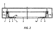
- FIG. 2 is a transverse cross sectional view of the flat panel display device illustrated in FIG. 1A ;
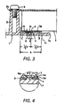
- FIG. 3 is a partial cross sectional view of the flat panel display device illustrated in FIG. 1A ;
- FIG. 4 is a detail cross sectional view of the flat panel display device illustrating a state of receiving a fall impact
- FIG. 5 is a detail cross sectional view of a flat panel display device in accordance with a second embodiment of the present invention.
- FIG. 1A is a front perspective view of a flat panel display device (e.g., display device).
- the flat panel display device is a display device such as an LCD television set, liquid crystal monitor, or the like.
- the flat panel display device includes a display module, a front cabinet 1 and a rear cabinet 2.
- the display module includes a liquid crystal panel (e.g., display main body) 3, a bezel 3a and a rear face member 3b.
- the display module is housed in the front and rear cabinets 1 and 2 that are mated together.
- the bezel 3a is provided to an outer peripheral edge section of a front face of the liquid crystal panel 3.
- the rear face member 3b is disposed on a rear side of the liquid crystal panel 3 and protrudes outward of an outer periphery of the liquid crystal panel 3 at the rear side of the liquid crystal panel 3.
- the rear face member 3b has a plurality of screw insertion holes formed at spaced apart locations along the outer periphery of the liquid crystal panel 3.
- the liquid crystal panel 3 has liquid crystal cells.
- the liquid crystal cells are provided to a front part of the liquid crystal panel 3 and illuminated from a rear side with a cold cathode fluorescent lamp (CCFL) (not shown) to display a video image on the liquid crystal panel 3.
- the rear cabinet 2 is disposed on a rear side of the display module.
- the front cabinet 1 is attached to a front side of the rear cabinet 2 to house the display module.
- the front cabinet 1 includes a front frame portion 1b, a support rib (e.g., first rib) 4, a plurality of bosses 8 and a retainer rib (e.g., second rib) 9.
- the front cabinet 1 is integrally formed as a one-piece unitary member.
- at least the front frame portion 1b, the support rib 4 and the retainer rib 9 are integrally formed as a one-piece unitary member.
- the front frame portion 1b defines a front face opening (e.g., window) 1a inward of the front frame portion 1b.
- the front face opening 1a exposes a part of the front face of the liquid crystal panel 3.
- the support rib 4 has a peak ridge with a tapered cross sectional shape having a peak.
- the peak ridge includes a bezel-opposing face 4a facing the bezel 3a.
- the support rib 4 is integrally formed on the front frame portion 1b.
- the support rib 4 extends along the front frame portion 1b to surround the front face opening 1a so that the support rib 4 has an annular shape with a substantially rectangular outer periphery in a front elevational view. In other words, the support rib 4 forms in a continuous annular ring shape.
- the support rib 4 protrudes rearward from a rear face of the front frame portion 1b so that the bezel-opposing face 4a of the support rib 4 contacts with a peripheral edge portion of the front face of the display module. Specifically, the bezel-opposing face 4a of the support rib 4 contacts with a front face of the bezel 3a.
- the bezel-opposing face 4a is formed in a tapered shape. Specifically, the bezel-opposing face 4a has a semicircular cross sectional shape with a radius r. A distal end of the bezel-opposing face 4a (linear contact portion A) contacts with the bezel 3a with a linear contact.
- the distal end of the bezel-opposing face 4a contacts with the bezel 3a at a midpoint (1/2k) of a total width k from an outer periphery of the bezel 3a to an inner periphery of the bezel 3a.
- the bosses 8 are integrally formed on the front frame portion 1a at locations spaced apart along the front frame portion 1a and outward of the support rib 4 with respect to the front face opening 1a.
- Each of the bosses 8 has a threaded hole at a center of the bosses 8.
- the screw insertion holes of the rear face member 3b are formed at locations corresponding to the threaded holes of the bosses 8.
- a plurality of screws 5 are inserted through the screw insertion holes of the rear face member 3b and threaded into the threaded holes of the bosses 8 to fix the display module to the front cabinet 1. As a result, the liquid crystal panel 3 of the display module is pressed against the support rib 4 of the front cabinet 1.
- the retainer rib 9 has a flat top face 9a having a specific width t.
- the retainer rib 9 is integrally formed on the front frame portion 1b at a location outward of the support rib 4 with respect to the front face opening 1a with a spacing between the support rib 4 and the retainer rib 9.
- the retainer rib 9 extends along the front frame portion 1b to surround the front face opening 1a so that the retainer rib 9 has an annular shape with a substantially rectangular outer periphery in a front elevational view. In other words, the retainer rib 9 forms in a continuous annular ring shape.
- the retainer rib 9 protrudes rearward from the rear face of the front frame portion 1b.
- the retainer rib 9 is located between the support rib 4 and the bosses 8 at a location closer to the support rib 4 than the bosses 8.
- the retainer rib 9 has shorter height than the support rib 4. Therefore, the flat top face 9a faces the bezel 3a with a narrow gap ⁇ therebetween.
- the flat top face 9a is disposed in parallel to the bezel 3a.
- the radius r of the bezel-opposing face 4a of the support rib 4 is 1 mm.
- the spacing s between centers of the support rib 4 and the retainer rib 9 is 3 mm.
- the width t of the flat top face 9a of the retainer rib 9 is 2 mm.
- the gap ⁇ between the bezel 3a and the flat top face 9a of the retainer rib 9 (or a height difference between the support rib 4 and the retainer rib 9) has a predetermined width m in a range of 0.1 to 0.3 mm (and preferably a range of 0.15 to 0.25 mm). More specifically, the width m of the gap ⁇ is 0.2 mm.
- the width k of the bezel 3a is 20 mm.
- the liquid crystal panel 3 is inserted into the front cabinet 1 so that the bezel 3a contacts with the bezel-opposing face 4a of the support rib 4 with a planar contact.
- the screws 5 are inserted through the screw insertion holes of the rear face member 3b and threaded into the threaded holes of the bosses 8 to fix the display module at a specific location within the front cabinet 1.
- the liquid crystal panel 3 of the display module is pressed against the support rib 4 of the front cabinet 1 with a pressing force F.
- the rear cabinet 2 is attached to the front cabinet 1 to house the display module within the front and rear cabinets 1 and 2.
- the width m of the gap ⁇ is less than 0.1 mm, then dimensional error and so forth can result in a state in which the bezel 3 a of the display module contacts with the flat top face 9a of the retainer rib 9 from the outset. If this happens, then vibration imparted to the liquid crystal panel 3 can cause the flat top face 9a of the retainer rib 9 and the bezel 3a to rub against each other and generate vibration noise known as chatter, which is unpleasant to the user. Also, a powdery coating can also be produced, which will adhere to a surface of the liquid crystal panel 3 and lower the appearance of the flat panel display device.
- the liquid crystal panel 3 can not be supported as intended when the liquid crystal panel 3 is subjected to impact due to a fall, for example.
- the impact can cause the linear contact portion A of the bezel-opposing face 4a of the support rib 4 to be pressed down by the bezel 3a of the liquid crystal panel 3.
- the bezel 3a of the liquid crystal panel 3 will not hit the flat top face 9a of the retainer rib 9.
- the impact will be concentrated in the support rib 4.
- the support rib 4 will be damaged or deformed and will no longer be able to support the liquid crystal panel 3 as intended.
- the width m of the gap ⁇ is set to between 0.1 and 0.3 mm (and preferably between 0.15 and 0.25 mm).
- the flat top face 9a of the retainer rib 9 usually does not touch the bezel 3a of the liquid crystal panel 3.
- the bezel-opposing face 4a of the support rib 4 contacts with the bezel 3a all the way around in a state of linear contact, and the pressing force F is concentrated in the linear contact portion A.
- the bezel-opposing face 4a of the support rib 4 fits snugly against the bezel 3a all the way around.
- the liquid crystal panel 3 is subjected to impact due to a fall, for example, then the linear contact portion A of the bezel-opposing face 4a of the support rib 4 is pressed down by the bezel 3a of the display module due to the impact. Then, the bezel 3a hits the flat top face 9a of the retainer rib 9 that is adjacent to the support rib 4, and receives the impact.
- the liquid crystal panel 3 can be reliably and securely supported so that the liquid crystal panel 3 does not move accidentally from the intended location.
- the liquid crystal panel 3 is pressed against and fixed to the support rib 4 by threading the screws 5 into the threaded holes of the bosses 8. Furthermore, the retainer rib 9 is located between the support rib 4 and the bosses 8 to which the display module is fixed. Thus, the width m of the gap ⁇ between the retainer rib 9 and the bezel 3a can be precisely set as intended.
- the spacing s between the centers of the support rib 4 and the retainer rib 9 is set extremely small. Furthermore, the retainer rib 9 is located close to the support rib 4. Thus, when the linear contact portion A of the bezel-opposing face 4a of the support rib 4 is pressed down by the bezel 3a under impact due to falling, for example, the retainer rib 9 immediately receives the impact as shown in FIG. 4 . As a result, the liquid crystal panel 3 can be reliably held down so that the liquid crystal panel 3 does not move accidentally from the intended location.
- the support rib 4 When the support rib 4 is pressed against an inner edge B or an outer edge C away from the center of the bezel 3a, there is a risk that the pressing force will deform the bezel 3a. Furthermore, the liquid crystal panel 3 will be subjected to a local load due to the deformation of the bezel 3a, and this load will produce color unevenness on the liquid crystal panel 3. However, with the flat panel display device, the support rib 4 is pressed against the center (1/2k) of the total width k of the bezel 3a. Thus, the pressing force is applied uniformly over the entire bezel 3a. As a result, the bezel 3a is not deformed. Thus, the liquid crystal panel 3 remains in a sharp display state, without causing color unevenness.
- the flat panel display device an LCD television set or a liquid crystal monitor is provided with which generation of vibration noise and powdery coatings can be eliminated. Furthermore, the flat panel display device can effectively withstand a fall impact with an inexpensive structure.
- the shape of the support rib 4 is not limited to the above-mentioned shape. Various shapes can be employed as shown in FIG. 5 .
- FIG. 5 is a detail cross sectional view of the support rib 4 in accordance with a second embodiment of the present invention.
- the parts of the second embodiment that are identical to the parts of the first embodiment will be given the same reference numerals as the parts of the first embodiment.
- the descriptions of the parts of the second embodiment that are identical to the parts of the first embodiment may be omitted for the sake of brevity.
- the distal end of the support rib 4" is formed in a pointed shape.
- the bezel-opposing face 4a" of the support rib 4" is a tapering roof-shaped face.
- the linear contact portion A" that is the distal end of the bezel-opposing face 4a" contacts with the bezel 3a with a linear contact.
- the action and effect are substantially the same as with the configuration shown in FIGS. 1 to 4 .
Landscapes
- Physics & Mathematics (AREA)
- Nonlinear Science (AREA)
- Mathematical Physics (AREA)
- Chemical & Material Sciences (AREA)
- Crystallography & Structural Chemistry (AREA)
- General Physics & Mathematics (AREA)
- Optics & Photonics (AREA)
- Devices For Indicating Variable Information By Combining Individual Elements (AREA)
- Liquid Crystal (AREA)
Priority Applications (1)
| Application Number | Priority Date | Filing Date | Title |
|---|---|---|---|
| PL08010733T PL2015131T3 (pl) | 2007-06-12 | 2008-06-12 | Urządzenie do wyświetlania |
Applications Claiming Priority (1)
| Application Number | Priority Date | Filing Date | Title |
|---|---|---|---|
| JP2007155564A JP4306766B2 (ja) | 2007-06-12 | 2007-06-12 | 薄型表示装置 |
Publications (2)
| Publication Number | Publication Date |
|---|---|
| EP2015131A1 true EP2015131A1 (fr) | 2009-01-14 |
| EP2015131B1 EP2015131B1 (fr) | 2010-02-10 |
Family
ID=39719067
Family Applications (1)
| Application Number | Title | Priority Date | Filing Date |
|---|---|---|---|
| EP08010733A Not-in-force EP2015131B1 (fr) | 2007-06-12 | 2008-06-12 | Dispositif d'affichage |
Country Status (5)
| Country | Link |
|---|---|
| US (1) | US7952655B2 (fr) |
| EP (1) | EP2015131B1 (fr) |
| JP (1) | JP4306766B2 (fr) |
| DE (1) | DE602008000630D1 (fr) |
| PL (1) | PL2015131T3 (fr) |
Cited By (2)
| Publication number | Priority date | Publication date | Assignee | Title |
|---|---|---|---|---|
| EP2244476A1 (fr) * | 2009-04-20 | 2010-10-27 | Funai Electric Co., Ltd. | Dispositif d'affichage pour écran plat |
| EP2511740A1 (fr) * | 2011-04-11 | 2012-10-17 | Funai Electric Co., Ltd. | Affichage |
Families Citing this family (8)
| Publication number | Priority date | Publication date | Assignee | Title |
|---|---|---|---|---|
| JP2010072366A (ja) * | 2008-09-18 | 2010-04-02 | Sharp Corp | 表示装置 |
| JP2010181665A (ja) | 2009-02-06 | 2010-08-19 | Funai Electric Co Ltd | 表示装置のキャビネット構造 |
| US8102483B2 (en) | 2010-03-08 | 2012-01-24 | Peerless Industries, Inc. | Display enclosure |
| US8081267B2 (en) * | 2010-03-08 | 2011-12-20 | Peerless Industries, Inc. | Display enclosure |
| USD669075S1 (en) | 2011-10-27 | 2012-10-16 | Ciil Technologies, Llc | Display enclosure for use with audio/visual devices or the like |
| US8714665B2 (en) | 2012-01-20 | 2014-05-06 | Ciil Technologies Llc | Enclosed television with improved enclosure sealing arrangement |
| US9078345B2 (en) | 2012-01-20 | 2015-07-07 | Ciil Technologies, Llc | Enclosed television with improved cable cover sealing mechanism |
| JP6715108B2 (ja) * | 2016-06-30 | 2020-07-01 | 古野電気株式会社 | 表示装置 |
Citations (7)
| Publication number | Priority date | Publication date | Assignee | Title |
|---|---|---|---|---|
| JPH07255024A (ja) | 1994-03-15 | 1995-10-03 | Sony Corp | 電子機器の外筐 |
| US6577288B1 (en) | 1998-03-20 | 2003-06-10 | Samsung Electronics Co., Ltd. | Flat panel display device for protecting a liquid crystal display thereof |
| US20050212991A1 (en) * | 2004-03-25 | 2005-09-29 | Nec Lcd Technologies, Ltd. | Liquid crystal display module and back light for the same |
| US20060082696A1 (en) | 2004-10-20 | 2006-04-20 | Sung-Gi Kim | Liquid crystal display apparatus |
| WO2006090543A1 (fr) | 2005-02-24 | 2006-08-31 | Matsushita Electric Industrial Co., Ltd. | Support de fixation de panneau et dispositif d'affichage |
| JP2007017513A (ja) * | 2005-07-05 | 2007-01-25 | Fujitsu General Ltd | 薄型表示装置 |
| JP2007155564A (ja) | 2005-12-07 | 2007-06-21 | Acrorad Co Ltd | 放射線検出器および放射線画像検出装置 |
Family Cites Families (3)
| Publication number | Priority date | Publication date | Assignee | Title |
|---|---|---|---|---|
| KR100381787B1 (ko) * | 2000-12-27 | 2003-04-26 | 삼성전자주식회사 | 디스플레이장치 |
| KR100784804B1 (ko) * | 2001-05-07 | 2007-12-14 | 삼성전자주식회사 | 액정 표시 장치 및 제조 방법 |
| US8786796B2 (en) * | 2007-10-29 | 2014-07-22 | Sharp Kabushiki Kaisha | Display device |
-
2007
- 2007-06-12 JP JP2007155564A patent/JP4306766B2/ja not_active Expired - Fee Related
-
2008
- 2008-06-11 US US12/136,814 patent/US7952655B2/en not_active Expired - Fee Related
- 2008-06-12 PL PL08010733T patent/PL2015131T3/pl unknown
- 2008-06-12 DE DE602008000630T patent/DE602008000630D1/de active Active
- 2008-06-12 EP EP08010733A patent/EP2015131B1/fr not_active Not-in-force
Patent Citations (7)
| Publication number | Priority date | Publication date | Assignee | Title |
|---|---|---|---|---|
| JPH07255024A (ja) | 1994-03-15 | 1995-10-03 | Sony Corp | 電子機器の外筐 |
| US6577288B1 (en) | 1998-03-20 | 2003-06-10 | Samsung Electronics Co., Ltd. | Flat panel display device for protecting a liquid crystal display thereof |
| US20050212991A1 (en) * | 2004-03-25 | 2005-09-29 | Nec Lcd Technologies, Ltd. | Liquid crystal display module and back light for the same |
| US20060082696A1 (en) | 2004-10-20 | 2006-04-20 | Sung-Gi Kim | Liquid crystal display apparatus |
| WO2006090543A1 (fr) | 2005-02-24 | 2006-08-31 | Matsushita Electric Industrial Co., Ltd. | Support de fixation de panneau et dispositif d'affichage |
| JP2007017513A (ja) * | 2005-07-05 | 2007-01-25 | Fujitsu General Ltd | 薄型表示装置 |
| JP2007155564A (ja) | 2005-12-07 | 2007-06-21 | Acrorad Co Ltd | 放射線検出器および放射線画像検出装置 |
Cited By (3)
| Publication number | Priority date | Publication date | Assignee | Title |
|---|---|---|---|---|
| EP2244476A1 (fr) * | 2009-04-20 | 2010-10-27 | Funai Electric Co., Ltd. | Dispositif d'affichage pour écran plat |
| US8243224B2 (en) | 2009-04-20 | 2012-08-14 | Funai Electric Co., Ltd. | Flat panel display device having a plurality of first bosses disposed on the rear face of a front panel and a bezel fixedly coupled to an outer peripheral portion |
| EP2511740A1 (fr) * | 2011-04-11 | 2012-10-17 | Funai Electric Co., Ltd. | Affichage |
Also Published As
| Publication number | Publication date |
|---|---|
| JP4306766B2 (ja) | 2009-08-05 |
| US7952655B2 (en) | 2011-05-31 |
| JP2008309890A (ja) | 2008-12-25 |
| PL2015131T3 (pl) | 2010-07-30 |
| EP2015131B1 (fr) | 2010-02-10 |
| US20080309843A1 (en) | 2008-12-18 |
| DE602008000630D1 (de) | 2010-03-25 |
Similar Documents
| Publication | Publication Date | Title |
|---|---|---|
| US7952655B2 (en) | Display device with secured support on frame | |
| EP3461305B1 (fr) | Appareil d'affichage | |
| KR100487435B1 (ko) | 마운팅 프레임 결합구조를 갖는 액정표시장치 모듈 | |
| US6525790B1 (en) | Liquid crystal module mounting structure | |
| KR100296154B1 (ko) | 액정표시장치모듈용 마운팅브라켓 | |
| US20060034090A1 (en) | Backlight assembly | |
| KR20050030867A (ko) | 액정표시장치 | |
| US10291877B2 (en) | Display and television set | |
| US6639635B2 (en) | Liquid crystal display device | |
| JP2008090181A (ja) | 表示パネル及び表示装置 | |
| US20100265641A1 (en) | Flat panel display device | |
| EP2352055A1 (fr) | Module à cristaux liquides et dispositif d'affichage | |
| US20050040738A1 (en) | Display apparatus | |
| US20070120878A1 (en) | Flat panel monitor including a frame having a protrusion | |
| US8243224B2 (en) | Flat panel display device having a plurality of first bosses disposed on the rear face of a front panel and a bezel fixedly coupled to an outer peripheral portion | |
| KR100319203B1 (ko) | 엘씨디모니터장치 | |
| WO2019146333A1 (fr) | Dispositif d'affichage | |
| US20070279581A1 (en) | Backlight module frame | |
| US8011624B2 (en) | Stand attachment structure | |
| JP2008227289A (ja) | 電子機器 | |
| KR100769165B1 (ko) | 평판표시장치와 시스템의 결합구조 | |
| KR20000031867A (ko) | 평판표시장치를 포함하는 컴퓨터 | |
| JP2013257387A (ja) | 表示装置及びテレビジョン受信機 | |
| CN114371574A (zh) | 一种支撑钉、背板、背光模组和显示装置 | |
| KR20070038200A (ko) | 액정표시장치 |
Legal Events
| Date | Code | Title | Description |
|---|---|---|---|
| PUAI | Public reference made under article 153(3) epc to a published international application that has entered the european phase |
Free format text: ORIGINAL CODE: 0009012 |
|
| PUAI | Public reference made under article 153(3) epc to a published international application that has entered the european phase |
Free format text: ORIGINAL CODE: 0009012 |
|
| AK | Designated contracting states |
Kind code of ref document: A1 Designated state(s): AT BE BG CH CY CZ DE DK EE ES FI FR GB GR HR HU IE IS IT LI LT LU LV MC MT NL NO PL PT RO SE SI SK TR |
|
| AX | Request for extension of the european patent |
Extension state: AL BA MK RS |
|
| 17P | Request for examination filed |
Effective date: 20090624 |
|
| GRAP | Despatch of communication of intention to grant a patent |
Free format text: ORIGINAL CODE: EPIDOSNIGR1 |
|
| AKX | Designation fees paid |
Designated state(s): DE FR GB PL |
|
| GRAS | Grant fee paid |
Free format text: ORIGINAL CODE: EPIDOSNIGR3 |
|
| GRAA | (expected) grant |
Free format text: ORIGINAL CODE: 0009210 |
|
| AK | Designated contracting states |
Kind code of ref document: B1 Designated state(s): DE FR GB PL |
|
| REG | Reference to a national code |
Ref country code: GB Ref legal event code: FG4D |
|
| REF | Corresponds to: |
Ref document number: 602008000630 Country of ref document: DE Date of ref document: 20100325 Kind code of ref document: P |
|
| REG | Reference to a national code |
Ref country code: PL Ref legal event code: T3 |
|
| PLBE | No opposition filed within time limit |
Free format text: ORIGINAL CODE: 0009261 |
|
| STAA | Information on the status of an ep patent application or granted ep patent |
Free format text: STATUS: NO OPPOSITION FILED WITHIN TIME LIMIT |
|
| 26N | No opposition filed |
Effective date: 20101111 |
|
| REG | Reference to a national code |
Ref country code: FR Ref legal event code: PLFP Year of fee payment: 9 |
|
| PGFP | Annual fee paid to national office [announced via postgrant information from national office to epo] |
Ref country code: GB Payment date: 20160608 Year of fee payment: 9 |
|
| PGFP | Annual fee paid to national office [announced via postgrant information from national office to epo] |
Ref country code: PL Payment date: 20160429 Year of fee payment: 9 Ref country code: FR Payment date: 20160516 Year of fee payment: 9 |
|
| REG | Reference to a national code |
Ref country code: DE Ref legal event code: R084 Ref document number: 602008000630 Country of ref document: DE |
|
| PGFP | Annual fee paid to national office [announced via postgrant information from national office to epo] |
Ref country code: DE Payment date: 20170606 Year of fee payment: 10 |
|
| GBPC | Gb: european patent ceased through non-payment of renewal fee |
Effective date: 20170612 |
|
| REG | Reference to a national code |
Ref country code: FR Ref legal event code: ST Effective date: 20180228 |
|
| PG25 | Lapsed in a contracting state [announced via postgrant information from national office to epo] |
Ref country code: GB Free format text: LAPSE BECAUSE OF NON-PAYMENT OF DUE FEES Effective date: 20170612 |
|
| PG25 | Lapsed in a contracting state [announced via postgrant information from national office to epo] |
Ref country code: FR Free format text: LAPSE BECAUSE OF NON-PAYMENT OF DUE FEES Effective date: 20170630 |
|
| REG | Reference to a national code |
Ref country code: DE Ref legal event code: R119 Ref document number: 602008000630 Country of ref document: DE |
|
| PG25 | Lapsed in a contracting state [announced via postgrant information from national office to epo] |
Ref country code: PL Free format text: LAPSE BECAUSE OF NON-PAYMENT OF DUE FEES Effective date: 20170612 |
|
| PG25 | Lapsed in a contracting state [announced via postgrant information from national office to epo] |
Ref country code: DE Free format text: LAPSE BECAUSE OF NON-PAYMENT OF DUE FEES Effective date: 20190101 |