EP2015153B1 - Système et procédé destinés au traitement d'un signal d'un commutateur à touche tactile - Google Patents
Système et procédé destinés au traitement d'un signal d'un commutateur à touche tactile Download PDFInfo
- Publication number
- EP2015153B1 EP2015153B1 EP07013564A EP07013564A EP2015153B1 EP 2015153 B1 EP2015153 B1 EP 2015153B1 EP 07013564 A EP07013564 A EP 07013564A EP 07013564 A EP07013564 A EP 07013564A EP 2015153 B1 EP2015153 B1 EP 2015153B1
- Authority
- EP
- European Patent Office
- Prior art keywords
- signal
- change
- spectrum
- range
- touch sensitive
- Prior art date
- Legal status (The legal status is an assumption and is not a legal conclusion. Google has not performed a legal analysis and makes no representation as to the accuracy of the status listed.)
- Active
Links
Images
Classifications
-
- G—PHYSICS
- G05—CONTROLLING; REGULATING
- G05B—CONTROL OR REGULATING SYSTEMS IN GENERAL; FUNCTIONAL ELEMENTS OF SUCH SYSTEMS; MONITORING OR TESTING ARRANGEMENTS FOR SUCH SYSTEMS OR ELEMENTS
- G05B23/00—Testing or monitoring of control systems or parts thereof
- G05B23/02—Electric testing or monitoring
- G05B23/0205—Electric testing or monitoring by means of a monitoring system capable of detecting and responding to faults
- G05B23/0218—Electric testing or monitoring by means of a monitoring system capable of detecting and responding to faults characterised by the fault detection method dealing with either existing or incipient faults
- G05B23/0224—Process history based detection method, e.g. whereby history implies the availability of large amounts of data
- G05B23/0227—Qualitative history assessment, whereby the type of data acted upon, e.g. waveforms, images or patterns, is not relevant, e.g. rule based assessment; if-then decisions
- G05B23/0235—Qualitative history assessment, whereby the type of data acted upon, e.g. waveforms, images or patterns, is not relevant, e.g. rule based assessment; if-then decisions based on a comparison with predetermined threshold or range, e.g. "classical methods", carried out during normal operation; threshold adaptation or choice; when or how to compare with the threshold
-
- H—ELECTRICITY
- H03—ELECTRONIC CIRCUITRY
- H03K—PULSE TECHNIQUE
- H03K17/00—Electronic switching or gating, i.e. not by contact-making and –breaking
- H03K17/94—Electronic switching or gating, i.e. not by contact-making and –breaking characterised by the way in which the control signals are generated
- H03K17/945—Proximity switches
-
- H—ELECTRICITY
- H03—ELECTRONIC CIRCUITRY
- H03K—PULSE TECHNIQUE
- H03K17/00—Electronic switching or gating, i.e. not by contact-making and –breaking
- H03K17/94—Electronic switching or gating, i.e. not by contact-making and –breaking characterised by the way in which the control signals are generated
- H03K17/96—Touch switches
-
- G—PHYSICS
- G05—CONTROLLING; REGULATING
- G05B—CONTROL OR REGULATING SYSTEMS IN GENERAL; FUNCTIONAL ELEMENTS OF SUCH SYSTEMS; MONITORING OR TESTING ARRANGEMENTS FOR SUCH SYSTEMS OR ELEMENTS
- G05B2219/00—Program-control systems
- G05B2219/30—Nc systems
- G05B2219/37—Measurements
- G05B2219/37536—Rate of change, derivative
-
- G—PHYSICS
- G05—CONTROLLING; REGULATING
- G05B—CONTROL OR REGULATING SYSTEMS IN GENERAL; FUNCTIONAL ELEMENTS OF SUCH SYSTEMS; MONITORING OR TESTING ARRANGEMENTS FOR SUCH SYSTEMS OR ELEMENTS
- G05B2219/00—Program-control systems
- G05B2219/30—Nc systems
- G05B2219/37—Measurements
- G05B2219/37579—Run away measured value by differentiating measured signal, rate of change
-
- H—ELECTRICITY
- H03—ELECTRONIC CIRCUITRY
- H03K—PULSE TECHNIQUE
- H03K2217/00—Indexing scheme related to electronic switching or gating, i.e. not by contact-making or -breaking covered by H03K17/00
- H03K2217/94—Indexing scheme related to electronic switching or gating, i.e. not by contact-making or -breaking covered by H03K17/00 characterised by the way in which the control signal is generated
- H03K2217/9401—Calibration techniques
- H03K2217/94026—Automatic threshold calibration; e.g. threshold automatically adapts to ambient conditions or follows variation of input
Definitions
- the present invention relates to a system for processing a signal from a touch sensitive key according to claim 1. Further, the present invention relates to a method for processing a signal from a touch sensitive key according to claim 5.
- Signals from electric devices represent or describe a certain state or an arbitrary analogue value.
- the information contained in said signals is used to control an apparatus or a process, for example.
- the signal may be a direct current (DC voltage) voltage signal.
- DC voltage direct current
- the value of the voltage characterizes the state of the device or the value of a quantity.
- the electric device may be a manual or an automatic switch. If the state of the switch is changed, then also the signal transmitted by said switch is changed. Further, the electric device may be a sensor element for detecting physical quantities, like temperature, pressure and humidity. The signal from the electric device represents the value of the detected quantity.
- a change of the state or the detected quantity may result in a relative small change of the signal.
- a change of the signals may be also caused by disturbances of the electric device or the system.
- the system has to distinguish, if the signal is disturbed or if the change of the signal bases on a real change of the state or detected value.
- the system for processing a signal from an electric device comprise:
- the main idea of the invention is the on one hand, that the reference value is continuously adapted, and on the other hand, that the complete spectrum of all possible difference values is subdivided into ranges. Said ranges correspond with the possible kinds of the causations for the disturbances.
- the continuous adapting allows that the reference value is always actualized.
- the continuous adapting avoids that two or more disturbances within a small time are identified as a change of the state or value in the electric device.
- the system recognizes, if said change is caused by a disturbance or by relevant change of the state or value. Further, the ranges allow, that the system recognizes, what kind of disturbance occurs.
- the spectrum includes all of the possible positive and negative difference values in view of the electric device. This allows identifying positive and negative changes of the signal.
- the reference value is continuously adapted to an actual value of the signal.
- This fast adaptation avoids that two or more disturbances are identified as change of the signal. For example, this behaviour may be used to detect a slow approach of a finger.
- the signal is an analogue signal.
- the signal is a direct current voltage (DC Voltage) signal.
- the signal may be characterized by its voltage.
- the frequency of an alternating current and other characteristic quantities may also be used as the signal.
- At least one of the ranges corresponds with temperature fluctuations.
- the temperature fluctuations disturb the electric device.
- the corresponding range allows identifying such temperature fluctuations.
- At least one of the ranges corresponds with noise, and hysteresis effects, respectively.
- At least one of the ranges corresponds with at least one of the relevant changes in the electric device.
- the system is able to distinguish between changes caused by disturbances and such changes caused by relevant changes in the electric device.
- the touch sensitive key provides relative small changes of the signal and the system is able to identify relevant signals.
- the system may be realized in hardware, software or a combination of hardware and software.
- the object of the present invention is also achieved by a method according to claim 5.
- the method for processing a signal from a touch sensitive key comprises the following steps:
- the inventive method actualizes continuously the reference value on the one hand and uses the complete spectrum of all possible difference values. Said spectrum is subdivided into ranges, which correspond with the possible kinds of the causations for the disturbances.
- the continuous adapting allows that the reference value is always actualized.
- the continuous adapting avoids that two or more disturbances within a relative small time are identified as a change of the value or the state in the electric device.
- a change of the signal occurs, it is recognized, if said change is caused by a disturbance or by a relevant change of the state or value.
- the ranges allow, that by the inventive method can be recognized, what kind of disturbance occurs.
- the used spectrum includes all of the positive and negative difference values in view of the electric device.
- the reference value is continuously adapted to an actual value of the signal.
- Such a fast adaptation avoids that two or more disturbances are identified as change of the signal.
- the received signal is an analogue signal and/or a direct current voltage (DC Voltage) signal.
- the received signal may be characterized by its voltage.
- the frequency of an alternating current and other characteristic quantities may also be used as the signal.
- the touch sensitive key provides relative small changes of the signal.
- the relevant signals may be distinguished from disturbances.
- the signal is received from a variable electric or electronic element and/or from a sensor for detecting at least one physical quantity.
- the method according to the present invention may be realized in hardware, software or a combination of hardware and software.
- a computer program product is provided.
- Said computer program product is stored on a computer usable medium, comprising computer readable program means for causing a computer to perform the method described above.
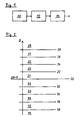
- FIG 1 illustrates a schematic block diagram of a system for processing a signal according to a preferred embodiment of the invention.
- the system includes an electric device 10, a detection circuit 12 and a processing unit 14.
- the electric device 10 provides a signal U.
- this signal can be a voltage, a current, a capacitive, an impedance and so on
- the detection circuit 12 receives the signal U from the electric device 10.
- the detection circuit 12 modifies, corrects and/or amplifies the signal U.
- the processing unit 14 processes the signal U in order to identify the state, request and/or value corresponding with the signal U.
- the electric device 10 may include electrical and/or mechanical elements.
- the electric device 10 comprises one or more sensors for detecting physical quantities, like temperature, pressure, brightness, weight and so on.
- the electric device 10 may be a manual switch.
- the electric device 10 is a touch sensitive key.
- the electric device 10 may be an arbitrary device, which provides the signal U describing a state and/or a value.
- the signal U is formed as an analogous voltage signal.
- the detection circuit 12 is preferably an electric circuit.
- the detection circuit 12 receives the signal U from the electric device 10.
- the detection circuit 12 modifies, corrects, amplifies and/or filters the signal U.
- the processing unit 14 receives the signal U from the detection circuit 12.
- the processing unit 14 compares the received signal U with a reference value U ref .
- the received signal U is continuously compared with the reference value U ref .
- the processing unit 14 determines a difference value AU between the signal U and the reference value U ref .
- the processing unit 14 comprise a spectrum of the possible difference values ⁇ U.
- the spectrum includes positive difference values ⁇ U as well as negative difference values ⁇ U.
- the spectrum is adapted to the electric device 10. Further, the spectrum may be adapted to the detection circuit 12.
- the spectrum is subdivided into ranges. Each of the ranges corresponds with a certain causation of the change of the received signal U. Comparing the change of the signal U with the spectrum the processing unit 14 is able to recognize the causation of said change. In particular, the processing unit 14 can recognize, if the change of the signal U is caused by a disturbance or real change of the state or the detected quantity in the electric device 10.
- the reference value U ref is continuously updated, so that the actual difference value ⁇ U is effectively the change of the signal U.
- the continuous updating of the reference value U ref avoids that two or more disturbances within a short time are misleadingly identified as a real change of the state or value in the electric device 10.
- FIG 2 illustrates a schematic diagram of a spectrum of possible difference values ⁇ U in the system according to the preferred embodiment of the invention.
- the spectrum is subdivided into several ranges. In this example the spectrum includes ten ranges limited by corresponding limit values.
- a first positive range 21 extends between the zero point 20 and a first positive limit value 22.
- a first negative range 31 extends between the zero point 20 and a first negative limit value 32.
- a second positive range 23 extends between the first positive limit value 22 and a second positive limit value 24.
- a second negative range 33 extends between the first negative limit value 32 and a second negative limit value 34.
- a third positive range 25 extends between the second positive limit value 24 and a third positive limit value 26.
- a third negative range 35 extends between the second negative limit value 34 and a third negative limit value 36.
- a fourth positive range 27 extends between the third positive limit value 26 and a fourth positive limit value 28.
- a fourth negative range 37 extends between the third negative limit value 36 and a fourth negative limit value 38.
- a fifth positive range 29 extends from the fourth positive limit value 28 up to arbitrary high positive values.
- a fifth negative range 39 extends from the fourth negative limit value 38 up to arbitrary low negative values.
- the difference values ⁇ U within the first positive range 21 and the first negative range 31 are caused by thermal fluctuations.
- the thermal fluctuations disturb the electric device 10 and/or the detection circuit 12 and result in a change of the signal U.
- the difference values ⁇ U within the second positive range 23 and the second negative range 33 in this example are caused by the noise.
- the noise occurs in electric circuits, in particular in the detection circuit 12 and also in the electric device 10.
- the noise also results in a change of the signal U.
- the difference values ⁇ U within the fourth positive range 27 and the fourth negative range 37 are the result of the hysteresis in order to avoid a re-bounce effect. If the precedent signal was detected in the fifth range, the fourth range will act as the fifth range. If the precedent signal was detected in the third range, the fourth range will act as the third range.
- the difference values ⁇ U within the fifth positive range 29 and the fifth negative range 39 are caused by real changes in the electric device 10. Said real changes may be the handling of a switch or the change of a detected physical quantity.
- the electric device 10 is a touch sensitive key. If the touch sensitive key is touched by the user, then a relative small change of the signal U from said touch sensitive key occurs. However, the change of the signal U after the touch is bigger than the change caused by a disturbance. Since the reference value U ref is continuously updated, two or more disturbances within a short time cannot be identified as a touch of the key.
- the inventive system and method can be used with various electric devices 10 and/or detection circuits 12.
- the inventive system and method are adaptable to those voltages, which correspond with the different states of the electric devices 10 and/or detection circuits 12.
- the present invention can also be embedded in a computer program product, which comprises all the features enabling the implementation of the method described herein. Further, when loaded in a computer system, said computer program product is able to carry out these methods.
Landscapes
- Physics & Mathematics (AREA)
- General Physics & Mathematics (AREA)
- Engineering & Computer Science (AREA)
- Automation & Control Theory (AREA)
- Electronic Switches (AREA)
- Electrophonic Musical Instruments (AREA)
- Circuits Of Receivers In General (AREA)
- Input Circuits Of Receivers And Coupling Of Receivers And Audio Equipment (AREA)
Claims (7)
- Système destiné au traitement d'un signal (U) provenant d'une touche tactile (10), dans lequel ledit système comprend:- un moyen pour représenter ou stocker une valeur de référence (Uref) pour le signal (U), dans lequel ladite valeur de référence (Uref) est continûment mise à jour et adaptée à une valeur réelle du signal (U),- une unité arithmétique pour déterminer une valeur de différence (ΔU) entre le signal (U) et la valeur de référence (Uref), de manière à ce que la valeur de différence (AU) corresponde à un changement du signal (U),- une unité de traitement (14) comprenant un spectre des valeurs de différence possibles (AU), où ledit spectre est subdivisé en plages (21, 23, 25, 27, 29, 31, 33, 35, 37, 39) correspondant aux causes possibles du changement du signal (U) dans ledit système, où au moins une plage (21, 31) correspond aux fluctuations de température, au moins une plage (23, 33) correspond au bruit, au moins une plage (27, 37) correspond à des effets d'hystérésis et au moins une plage (29, 39) correspond à au moins un des changements pertinents au niveau de la touche tactile (10), et- une unité de comparaison destinée à associer la valeur de différence (AU) à la plage correspondante (21, 23, 25, 27, 29, 31, 33, 35, 37, 39) du spectre et à identifier si la valeur de différence (AU) résulte d'une perturbation ou d'un changement pertinent au niveau de la touche tactile (10),- dans lequel le spectre comprend toutes les valeurs de différence positives et négatives possibles (AU) du point de vue de la touche tactile (10) pour identifier les changements positifs et négatifs du signal,- dans lequel chacune des plages correspond à une certaine causalité du changement du signal reçu (U),- dans lequel, en comparant le changement du signal (U) au spectre à l'aide de l'unité de traitement (14), la causalité dudit changement est reconnaissable.
- Système selon l'une quelconque des revendications précédentes, caractérisé en ce que le signal (U) est un signal analogique.
- Système selon l'une quelconque des revendications précédentes, caractérisé en ce que le signal (U) est un signal de courant continu et/ou le signal (U) est caractérisé par sa tension.
- Système selon l'une quelconque des revendications précédentes, caractérisé en ce que le système est un système matériel, un système logiciel ou une combinaison d'un système matériel et d'un système logiciel.
- Procédé destiné au traitement d'un signal (U) provenant d'une touche tactile (10), dans lequel ledit procédé comprend les étapes suivantes consistant à:- recevoir le signal (U) de la touche tactile (10) et optionnellement modifier ledit signal (U) à l'aide d'un circuit de détection (12),- définir une valeur de référence (Uref),- déterminer une valeur de différence (AU) entre le signal (U) et la valeur de référence (Uref),- fournir un spectre des valeurs de différence possibles (ΔU), où ledit spectre est subdivisé en plages (21, 23, 25, 27, 29, 31, 33, 35, 37, 39) correspondant aux causes possibles du changement du signal (U) au niveau de la touche tactile (10), où au moins une plage (21, 31) correspond à des fluctuations de température, au moins une plage (23, 33) correspond à du bruit, au moins une plage (27, 37) correspond à des effets d'hystérésis et au moins une plage (29, 39) correspond à au moins un des changements pertinents au niveau de la touche tactile (10),- comparer la valeur de différence (ΔU) au spectre,- associer la valeur de différence (ΔU) à la plage correspondante (21, 23, 25, 27, 29, 31, 33, 35, 37, 39) du spectre,- identifier si la valeur de différence (ΔU) résulte d'une perturbation ou d'un changement pertinent au niveau de la touche tactile (10), et- mettre à jour la valeur de référence (Uref),- dans lequel le spectre fourni comprend toutes les valeurs de différence positives et négatives possibles (ΔU) du point de vue de la touche tactile (10) pour identifier les changements positifs et négatifs du signal,- dans lequel la valeur de référence (Uref) est continûment adaptée à une valeur réelle du signal (U),- dans lequel chacune des plages correspond à une certaine causalité du changement du signal reçu (U),- dans lequel, en comparant le changement du signal (U) au spectre à l'aide de l'unité de traitement (14), la causalité dudit changement est reconnaissable.
- Procédé selon la revendication 5, caractérisé en ce que le signal reçu (U) est un signal analogique et/ou en ce que le signal reçu (U) est un signal de courant continu et/ou en ce que le signal reçu (U) est caractérisé par sa tension.
- Programme informatique stocké sur un support utilisable par un ordinateur comprenant des moyens logiciels lisibles par un ordinateur permettant qu'un ordinateur exécute un procédé selon l'une quelconque des revendications précédentes 5 à 6.
Priority Applications (8)
| Application Number | Priority Date | Filing Date | Title |
|---|---|---|---|
| AT07013564T ATE485543T1 (de) | 2007-07-11 | 2007-07-11 | System und verfahren zur verarbeitung eines signals eines berührungsempfindlichen tastschalters |
| EP07013564A EP2015153B1 (fr) | 2007-07-11 | 2007-07-11 | Système et procédé destinés au traitement d'un signal d'un commutateur à touche tactile |
| DE602007009962T DE602007009962D1 (de) | 2007-07-11 | 2007-07-11 | System und Verfahren zur Verarbeitung eines Signals eines berührungsempfindlichen Tastschalters |
| CA002682970A CA2682970A1 (fr) | 2007-07-11 | 2008-07-01 | Systeme et procede pour traiter un signal provenant d'un dispositif electrique |
| CN2008800214253A CN101681156B (zh) | 2007-07-11 | 2008-07-01 | 处理电气装置的信号的系统和方法 |
| AU2008274592A AU2008274592B2 (en) | 2007-07-11 | 2008-07-01 | A system and a method for processing a signal from an electric device |
| US12/667,317 US8243037B2 (en) | 2007-07-11 | 2008-07-01 | System and a method for processing a signal from an electric device |
| PCT/EP2008/005359 WO2009007041A1 (fr) | 2007-07-11 | 2008-07-01 | Système et procédé pour traiter un signal provenant d'un dispositif électrique |
Applications Claiming Priority (1)
| Application Number | Priority Date | Filing Date | Title |
|---|---|---|---|
| EP07013564A EP2015153B1 (fr) | 2007-07-11 | 2007-07-11 | Système et procédé destinés au traitement d'un signal d'un commutateur à touche tactile |
Publications (2)
| Publication Number | Publication Date |
|---|---|
| EP2015153A1 EP2015153A1 (fr) | 2009-01-14 |
| EP2015153B1 true EP2015153B1 (fr) | 2010-10-20 |
Family
ID=38596811
Family Applications (1)
| Application Number | Title | Priority Date | Filing Date |
|---|---|---|---|
| EP07013564A Active EP2015153B1 (fr) | 2007-07-11 | 2007-07-11 | Système et procédé destinés au traitement d'un signal d'un commutateur à touche tactile |
Country Status (8)
| Country | Link |
|---|---|
| US (1) | US8243037B2 (fr) |
| EP (1) | EP2015153B1 (fr) |
| CN (1) | CN101681156B (fr) |
| AT (1) | ATE485543T1 (fr) |
| AU (1) | AU2008274592B2 (fr) |
| CA (1) | CA2682970A1 (fr) |
| DE (1) | DE602007009962D1 (fr) |
| WO (1) | WO2009007041A1 (fr) |
Families Citing this family (2)
| Publication number | Priority date | Publication date | Assignee | Title |
|---|---|---|---|---|
| US10679212B2 (en) | 2014-05-26 | 2020-06-09 | The Toronto-Dominion Bank | Post-manufacture configuration of pin-pad terminals |
| CN106557201B (zh) * | 2016-10-19 | 2020-06-02 | 北京小米移动软件有限公司 | 压力检测方法及装置 |
Family Cites Families (8)
| Publication number | Priority date | Publication date | Assignee | Title |
|---|---|---|---|---|
| AT266475B (de) * | 1966-07-26 | 1968-11-25 | Oesterr Studien Atomenergie | Verfahren und Vorrichtung zur Erzeugung eines Regelsignales für automatisch gesteuerte Einrichtungen |
| US4442495A (en) | 1980-02-27 | 1984-04-10 | Cadtrak Corporation | Real time toroidal pan |
| US4442494A (en) * | 1981-11-18 | 1984-04-10 | Westinghouse Electric Corp. | Tool wear and tool failure monitor system |
| DE3311861A1 (de) * | 1983-03-31 | 1984-10-04 | Werkzeugmaschinenbau Präzisions-Technik GmbH Wertheim, 6980 Wertheim | Verfahren zum ueberwachen des betriebsverhaltens von projektions-formen-schleifmaschinen |
| US4866363A (en) * | 1987-09-21 | 1989-09-12 | Honeywell Inc. | Fail-safe potentiometer feedback system |
| DE19620059B4 (de) * | 1996-05-20 | 2004-12-23 | Ifm Electronic Gmbh | Schaltungsanordnung zum Entriegeln mindestens eines Türschlosses eines Kraftfahrzeugs |
| DE19622027C1 (de) * | 1996-05-31 | 1997-07-31 | Inventa Ag | Hochschrumpfende PA-Fasern und -Garne und Verfahren zu ihrer Herstellung sowie deren Verwendung |
| US5854744A (en) * | 1996-06-25 | 1998-12-29 | Ingersoll-Rand Company | Adaptive process control system |
-
2007
- 2007-07-11 EP EP07013564A patent/EP2015153B1/fr active Active
- 2007-07-11 AT AT07013564T patent/ATE485543T1/de not_active IP Right Cessation
- 2007-07-11 DE DE602007009962T patent/DE602007009962D1/de active Active
-
2008
- 2008-07-01 CA CA002682970A patent/CA2682970A1/fr not_active Abandoned
- 2008-07-01 AU AU2008274592A patent/AU2008274592B2/en not_active Ceased
- 2008-07-01 US US12/667,317 patent/US8243037B2/en active Active
- 2008-07-01 CN CN2008800214253A patent/CN101681156B/zh active Active
- 2008-07-01 WO PCT/EP2008/005359 patent/WO2009007041A1/fr not_active Ceased
Also Published As
| Publication number | Publication date |
|---|---|
| ATE485543T1 (de) | 2010-11-15 |
| CN101681156B (zh) | 2012-09-19 |
| EP2015153A1 (fr) | 2009-01-14 |
| US8243037B2 (en) | 2012-08-14 |
| WO2009007041A1 (fr) | 2009-01-15 |
| CA2682970A1 (fr) | 2009-01-15 |
| AU2008274592A1 (en) | 2009-01-15 |
| US20100207896A1 (en) | 2010-08-19 |
| AU2008274592B2 (en) | 2011-04-21 |
| DE602007009962D1 (de) | 2010-12-02 |
| CN101681156A (zh) | 2010-03-24 |
Similar Documents
| Publication | Publication Date | Title |
|---|---|---|
| US8786573B2 (en) | Data input device of electronic device and input control method | |
| KR101148297B1 (ko) | 터치 센서 장치, 제어 방법, 터치 패널 장치 및 프로그램을 저장한 기억 매체 | |
| US9830018B2 (en) | Touch control apparatus and noise compensating circuit and method thereof | |
| US8050876B2 (en) | Automatic environmental compensation of capacitance based proximity sensors | |
| KR102110183B1 (ko) | 터치 입력 장치의 감도 보정 방법 및 이를 채용한 터치 입력 장치 | |
| US20130194234A1 (en) | Sensing circuit and method for a capacitive touch panel | |
| US8368572B2 (en) | Detecting device | |
| CN103294233A (zh) | 触摸屏和具有该触摸屏的触摸显示装置 | |
| CN110134281B (zh) | 电容检测系统及方法 | |
| EP3026532B1 (fr) | Procédé de détection utilisant un capteur capacitif, et dispositif électronique | |
| EP2015153B1 (fr) | Système et procédé destinés au traitement d'un signal d'un commutateur à touche tactile | |
| US12474185B2 (en) | Capacitive sensor device with drift compensation | |
| JP2012216028A (ja) | 電子機器用の入力装置及び入力方法 | |
| US20190369803A1 (en) | Method of detecting liquid on a capacitive touchpad and controller thereof | |
| US8170822B2 (en) | Compensation method for touch sensor system | |
| KR20150081110A (ko) | 터치 패널의 터치 압력 감지 방법, 장치 및 이를 이용한 터치 센싱 장치 | |
| HK1141340A (en) | A system and a method for processing a signal from an electric device | |
| US20210389840A1 (en) | Method for updating environmental threshold in touch sensing, touch sensor, and water outlet device | |
| EP4300274B1 (fr) | Dispositif à panneau tactile | |
| TWI425402B (zh) | Sensing method and circuit for capacitive touch panel | |
| US20100245132A1 (en) | Compensation method for touch sensor system | |
| JP2022011495A (ja) | スイッチ装置 | |
| CN107664656A (zh) | 材料辨识系统及材料辨识方法 |
Legal Events
| Date | Code | Title | Description |
|---|---|---|---|
| PUAI | Public reference made under article 153(3) epc to a published international application that has entered the european phase |
Free format text: ORIGINAL CODE: 0009012 |
|
| 17P | Request for examination filed |
Effective date: 20080910 |
|
| AK | Designated contracting states |
Kind code of ref document: A1 Designated state(s): AT BE BG CH CY CZ DE DK EE ES FI FR GB GR HU IE IS IT LI LT LU LV MC MT NL PL PT RO SE SI SK TR |
|
| AX | Request for extension of the european patent |
Extension state: AL BA HR MK RS |
|
| 17Q | First examination report despatched |
Effective date: 20090317 |
|
| AKX | Designation fees paid |
Designated state(s): AT BE BG CH CY CZ DE DK EE ES FI FR GB GR HU IE IS IT LI LT LU LV MC MT NL PL PT RO SE SI SK TR |
|
| GRAP | Despatch of communication of intention to grant a patent |
Free format text: ORIGINAL CODE: EPIDOSNIGR1 |
|
| RTI1 | Title (correction) |
Free format text: A SYSTEM AND A METHOD FOR PROCESSING A SIGNAL FROM A TOUCH SENSITIVE KEY |
|
| GRAS | Grant fee paid |
Free format text: ORIGINAL CODE: EPIDOSNIGR3 |
|
| GRAA | (expected) grant |
Free format text: ORIGINAL CODE: 0009210 |
|
| AK | Designated contracting states |
Kind code of ref document: B1 Designated state(s): AT BE BG CH CY CZ DE DK EE ES FI FR GB GR HU IE IS IT LI LT LU LV MC MT NL PL PT RO SE SI SK TR |
|
| REG | Reference to a national code |
Ref country code: GB Ref legal event code: FG4D |
|
| REG | Reference to a national code |
Ref country code: CH Ref legal event code: EP |
|
| REG | Reference to a national code |
Ref country code: IE Ref legal event code: FG4D |
|
| REF | Corresponds to: |
Ref document number: 602007009962 Country of ref document: DE Date of ref document: 20101202 Kind code of ref document: P |
|
| REG | Reference to a national code |
Ref country code: SE Ref legal event code: TRGR |
|
| REG | Reference to a national code |
Ref country code: NL Ref legal event code: VDEP Effective date: 20101020 |
|
| RAP2 | Party data changed (patent owner data changed or rights of a patent transferred) |
Owner name: ELECTROLUX HOME PRODUCTS CORPORATION N.V. |
|
| LTIE | Lt: invalidation of european patent or patent extension |
Effective date: 20101020 |
|
| REG | Reference to a national code |
Ref country code: DE Ref legal event code: R081 Ref document number: 602007009962 Country of ref document: DE Owner name: ELECTROLUX HOME PRODUCTS CORPORATION N.V., BE Free format text: FORMER OWNER: ELECTROLUX HOME PRODUCTS CORPORATION N.V., ZAVENTEM, BE Effective date: 20110201 |
|
| PG25 | Lapsed in a contracting state [announced via postgrant information from national office to epo] |
Ref country code: LT Free format text: LAPSE BECAUSE OF FAILURE TO SUBMIT A TRANSLATION OF THE DESCRIPTION OR TO PAY THE FEE WITHIN THE PRESCRIBED TIME-LIMIT Effective date: 20101020 |
|
| PG25 | Lapsed in a contracting state [announced via postgrant information from national office to epo] |
Ref country code: LV Free format text: LAPSE BECAUSE OF FAILURE TO SUBMIT A TRANSLATION OF THE DESCRIPTION OR TO PAY THE FEE WITHIN THE PRESCRIBED TIME-LIMIT Effective date: 20101020 Ref country code: IS Free format text: LAPSE BECAUSE OF FAILURE TO SUBMIT A TRANSLATION OF THE DESCRIPTION OR TO PAY THE FEE WITHIN THE PRESCRIBED TIME-LIMIT Effective date: 20110220 Ref country code: PT Free format text: LAPSE BECAUSE OF FAILURE TO SUBMIT A TRANSLATION OF THE DESCRIPTION OR TO PAY THE FEE WITHIN THE PRESCRIBED TIME-LIMIT Effective date: 20110221 Ref country code: FI Free format text: LAPSE BECAUSE OF FAILURE TO SUBMIT A TRANSLATION OF THE DESCRIPTION OR TO PAY THE FEE WITHIN THE PRESCRIBED TIME-LIMIT Effective date: 20101020 Ref country code: SI Free format text: LAPSE BECAUSE OF FAILURE TO SUBMIT A TRANSLATION OF THE DESCRIPTION OR TO PAY THE FEE WITHIN THE PRESCRIBED TIME-LIMIT Effective date: 20101020 Ref country code: AT Free format text: LAPSE BECAUSE OF FAILURE TO SUBMIT A TRANSLATION OF THE DESCRIPTION OR TO PAY THE FEE WITHIN THE PRESCRIBED TIME-LIMIT Effective date: 20101020 Ref country code: BG Free format text: LAPSE BECAUSE OF FAILURE TO SUBMIT A TRANSLATION OF THE DESCRIPTION OR TO PAY THE FEE WITHIN THE PRESCRIBED TIME-LIMIT Effective date: 20110120 Ref country code: NL Free format text: LAPSE BECAUSE OF FAILURE TO SUBMIT A TRANSLATION OF THE DESCRIPTION OR TO PAY THE FEE WITHIN THE PRESCRIBED TIME-LIMIT Effective date: 20101020 |
|
| PG25 | Lapsed in a contracting state [announced via postgrant information from national office to epo] |
Ref country code: BE Free format text: LAPSE BECAUSE OF FAILURE TO SUBMIT A TRANSLATION OF THE DESCRIPTION OR TO PAY THE FEE WITHIN THE PRESCRIBED TIME-LIMIT Effective date: 20101020 Ref country code: GR Free format text: LAPSE BECAUSE OF FAILURE TO SUBMIT A TRANSLATION OF THE DESCRIPTION OR TO PAY THE FEE WITHIN THE PRESCRIBED TIME-LIMIT Effective date: 20110121 |
|
| PG25 | Lapsed in a contracting state [announced via postgrant information from national office to epo] |
Ref country code: ES Free format text: LAPSE BECAUSE OF FAILURE TO SUBMIT A TRANSLATION OF THE DESCRIPTION OR TO PAY THE FEE WITHIN THE PRESCRIBED TIME-LIMIT Effective date: 20110131 Ref country code: EE Free format text: LAPSE BECAUSE OF FAILURE TO SUBMIT A TRANSLATION OF THE DESCRIPTION OR TO PAY THE FEE WITHIN THE PRESCRIBED TIME-LIMIT Effective date: 20101020 Ref country code: CZ Free format text: LAPSE BECAUSE OF FAILURE TO SUBMIT A TRANSLATION OF THE DESCRIPTION OR TO PAY THE FEE WITHIN THE PRESCRIBED TIME-LIMIT Effective date: 20101020 |
|
| PLBE | No opposition filed within time limit |
Free format text: ORIGINAL CODE: 0009261 |
|
| STAA | Information on the status of an ep patent application or granted ep patent |
Free format text: STATUS: NO OPPOSITION FILED WITHIN TIME LIMIT |
|
| PG25 | Lapsed in a contracting state [announced via postgrant information from national office to epo] |
Ref country code: SK Free format text: LAPSE BECAUSE OF FAILURE TO SUBMIT A TRANSLATION OF THE DESCRIPTION OR TO PAY THE FEE WITHIN THE PRESCRIBED TIME-LIMIT Effective date: 20101020 Ref country code: RO Free format text: LAPSE BECAUSE OF FAILURE TO SUBMIT A TRANSLATION OF THE DESCRIPTION OR TO PAY THE FEE WITHIN THE PRESCRIBED TIME-LIMIT Effective date: 20101020 Ref country code: DK Free format text: LAPSE BECAUSE OF FAILURE TO SUBMIT A TRANSLATION OF THE DESCRIPTION OR TO PAY THE FEE WITHIN THE PRESCRIBED TIME-LIMIT Effective date: 20101020 Ref country code: PL Free format text: LAPSE BECAUSE OF FAILURE TO SUBMIT A TRANSLATION OF THE DESCRIPTION OR TO PAY THE FEE WITHIN THE PRESCRIBED TIME-LIMIT Effective date: 20101020 |
|
| 26N | No opposition filed |
Effective date: 20110721 |
|
| REG | Reference to a national code |
Ref country code: DE Ref legal event code: R097 Ref document number: 602007009962 Country of ref document: DE Effective date: 20110721 |
|
| PGFP | Annual fee paid to national office [announced via postgrant information from national office to epo] |
Ref country code: GB Payment date: 20110721 Year of fee payment: 5 Ref country code: SE Payment date: 20110722 Year of fee payment: 5 |
|
| PG25 | Lapsed in a contracting state [announced via postgrant information from national office to epo] |
Ref country code: MT Free format text: LAPSE BECAUSE OF FAILURE TO SUBMIT A TRANSLATION OF THE DESCRIPTION OR TO PAY THE FEE WITHIN THE PRESCRIBED TIME-LIMIT Effective date: 20101020 |
|
| PG25 | Lapsed in a contracting state [announced via postgrant information from national office to epo] |
Ref country code: MC Free format text: LAPSE BECAUSE OF NON-PAYMENT OF DUE FEES Effective date: 20110731 |
|
| REG | Reference to a national code |
Ref country code: CH Ref legal event code: PL |
|
| REG | Reference to a national code |
Ref country code: IE Ref legal event code: MM4A |
|
| PG25 | Lapsed in a contracting state [announced via postgrant information from national office to epo] |
Ref country code: LI Free format text: LAPSE BECAUSE OF NON-PAYMENT OF DUE FEES Effective date: 20110731 Ref country code: CH Free format text: LAPSE BECAUSE OF NON-PAYMENT OF DUE FEES Effective date: 20110731 |
|
| PG25 | Lapsed in a contracting state [announced via postgrant information from national office to epo] |
Ref country code: IE Free format text: LAPSE BECAUSE OF NON-PAYMENT OF DUE FEES Effective date: 20110711 |
|
| REG | Reference to a national code |
Ref country code: SE Ref legal event code: EUG |
|
| GBPC | Gb: european patent ceased through non-payment of renewal fee |
Effective date: 20120711 |
|
| PG25 | Lapsed in a contracting state [announced via postgrant information from national office to epo] |
Ref country code: SE Free format text: LAPSE BECAUSE OF NON-PAYMENT OF DUE FEES Effective date: 20120712 Ref country code: GB Free format text: LAPSE BECAUSE OF NON-PAYMENT OF DUE FEES Effective date: 20120711 |
|
| PG25 | Lapsed in a contracting state [announced via postgrant information from national office to epo] |
Ref country code: LU Free format text: LAPSE BECAUSE OF NON-PAYMENT OF DUE FEES Effective date: 20110711 Ref country code: CY Free format text: LAPSE BECAUSE OF EXPIRATION OF PROTECTION Effective date: 20101020 |
|
| PG25 | Lapsed in a contracting state [announced via postgrant information from national office to epo] |
Ref country code: TR Free format text: LAPSE BECAUSE OF FAILURE TO SUBMIT A TRANSLATION OF THE DESCRIPTION OR TO PAY THE FEE WITHIN THE PRESCRIBED TIME-LIMIT Effective date: 20101020 |
|
| PG25 | Lapsed in a contracting state [announced via postgrant information from national office to epo] |
Ref country code: HU Free format text: LAPSE BECAUSE OF FAILURE TO SUBMIT A TRANSLATION OF THE DESCRIPTION OR TO PAY THE FEE WITHIN THE PRESCRIBED TIME-LIMIT Effective date: 20101020 |
|
| REG | Reference to a national code |
Ref country code: FR Ref legal event code: PLFP Year of fee payment: 10 |
|
| REG | Reference to a national code |
Ref country code: FR Ref legal event code: PLFP Year of fee payment: 11 |
|
| REG | Reference to a national code |
Ref country code: FR Ref legal event code: PLFP Year of fee payment: 12 |
|
| P01 | Opt-out of the competence of the unified patent court (upc) registered |
Effective date: 20230625 |
|
| PGFP | Annual fee paid to national office [announced via postgrant information from national office to epo] |
Ref country code: DE Payment date: 20250728 Year of fee payment: 19 |
|
| PGFP | Annual fee paid to national office [announced via postgrant information from national office to epo] |
Ref country code: IT Payment date: 20250721 Year of fee payment: 19 |
|
| PGFP | Annual fee paid to national office [announced via postgrant information from national office to epo] |
Ref country code: FR Payment date: 20250725 Year of fee payment: 19 |