EP2015250A2 - Bildverarbeitungsprogrammprodukt und Bildverarbeitungsvorrichtung - Google Patents
Bildverarbeitungsprogrammprodukt und Bildverarbeitungsvorrichtung Download PDFInfo
- Publication number
- EP2015250A2 EP2015250A2 EP08157732A EP08157732A EP2015250A2 EP 2015250 A2 EP2015250 A2 EP 2015250A2 EP 08157732 A EP08157732 A EP 08157732A EP 08157732 A EP08157732 A EP 08157732A EP 2015250 A2 EP2015250 A2 EP 2015250A2
- Authority
- EP
- European Patent Office
- Prior art keywords
- area
- light source
- bright
- star
- image processing
- Prior art date
- Legal status (The legal status is an assumption and is not a legal conclusion. Google has not performed a legal analysis and makes no representation as to the accuracy of the status listed.)
- Granted
Links
Images


Classifications
-
- G—PHYSICS
- G06—COMPUTING OR CALCULATING; COUNTING
- G06T—IMAGE DATA PROCESSING OR GENERATION, IN GENERAL
- G06T11/00—Two-dimensional [2D] image generation
- G06T11/10—Texturing; Colouring; Generation of textures or colours
Definitions
- the present invention relates to an image processing program product and an image processing apparatus.
- Japanese Laid Open Patent Publication No. 2005-92724 discloses a bright beam drawing processing method.
- a bright beam is drawn starting from a bright point pixel by detecting bright point pixels within an image.
- a computer-readable computer program product containing an image processing control program with the control program which comprises: a first area extraction instruction for extracting as a first area an area assuming an intensity value equal to or greater than a first threshold value from an image; a second area extraction instruction for extracting as a second area an area assuming a intensity value equal to or greater than a second threshold value smaller than the first threshold value from the image; and a light source area designation instruction for designating an area in the image that contains a light source as a light source area based upon characteristic quantities indicating characteristics of the first area and the second area.
- the image processing program product in the image processing program product according to the 1st aspect, it is preferred that a decision is made in response to the light source area designation instruction, as to whether or not the second area is the light source area based upon an inclusive relationship that may exist between the second area and the first area.
- a decision is made in response to the light source area designation instruction, as to whether or not the second area is the light source area based upon a ratio of an areal size of the second area and an areal size of the first area present within the second area.
- a decision is made in response to the light source area designation instruction, as to whether or not the second area is the light source area based upon a positional relationship between a gravitational center of the second area and a gravitational center of the first area present within the second area.
- a decision is made in response to the light source area designation instruction, as to whether or not the second area is the light source area based upon a ratio of an aerial size of the second area and an aerial size of the first area present within the second area and a positional relationship between a gravitational center of the second area and a gravitational center of the first area present within the second area.
- a light source position present inside the light source area is determined in response to the light source area designation instruction, based upon the positional relationship between the gravitational center of the second area and the gravitational center of the first area present within the second area.
- control program further comprises a bright beam drawing instruction for drawing bright beams along a plurality of directions from a starting point set at the light source position designated in response to the light source area designation instruction.
- control program further comprises a bright beam size determination instruction for determining a width and length of the bright beams to be drawn based upon a size of the image and the aerial size of the light source area.
- control program further comprises a bright beam color determination instruction for determining a color of the bright beams to be drawn based upon color information provided at a point set apart from the gravitational center of the light source area by a predetermined distance or more.
- control program further comprises: a bright beam color determination instruction for determining a color of the bright beams to be drawn based upon information provided at a point set apart from the gravitational center of the light source area by a predetermined distance or more, wherein: the bright beams are drawn in response to the bright beam drawing instruction, based upon the length of the bright beams determined in response to the bright beam size determination instruction and the color of the bright beams determined in response to the bright beam color determination instruction.
- the bright beams are drawn in response to the bright beam drawing instruction, so that intensity of the bright beams is attenuated through simple attenuation as a distance from the light source position increases if the length of the bright beams is smaller than a predetermined value and the bright beams are drawn so as to cyclically attenuate and amplify the intensity of the bright beams as the distance from the light source position increases if the length of the bright beams is equal to or greater than the predetermined value.
- the hue of the bright beams is cyclically altered in response to the bright beam drawing instruction, if the color of the bright beams is white.
- a light diffusion effect is rendered over and area where a plurality of bright beams intersect one another in response to the bright beam drawing instruction.
- an image processing apparatus comprising: a first area extraction means that extracts as a first area an area assuming an intensity value equal to or greater than a first threshold value from an image; a second area extraction means that extracts as a second area an area assuming an intensity value equal to or greater than a second threshold value smaller than the first threshold value from the image; a light source area designating means that designates as a light source area an area in the image containing a light source based upon characteristic quantities indicating characteristics of the first area and the second area; and a control means that controls the first area extraction means, the second area extraction means and the light source area designating means.
- the light source area designating means determines whether or not the second area is the light source area based upon a ratio of an aerial size of the second area and an aerial size of the first area present within the second area and a positional relationship between a gravitational center of the second area and a gravitational center of the first area present within the second area.
- the light source area designating means designates a light source position within the light source area based upon the positional relationship between the gravitational center of the second area and the gravitational center of the first area present within the second area.
- the image processing apparatus further comprises a bright beam drawing means that draws bright beams along a plurality directions from a starting point set at the light source position designated by the light source area designating means.
- the image processing apparatus further comprises: a bright beam size determining means that determines a width and a length of the bright beams to be drawn based upon a size of the image and the aerial size of the light source area; and a bright beam color determining means that determines a color of the bright beams to be drawn based upon color information provided at a point set apart from a gravitational center of the light source area by a predetermined distance or more, wherein: the bright beam drawing means draws the bright beams based upon the length of the bright beams determined by the bright beam size determining means and the color of the bright beams determined by the bright beam color determining means.
- FIG. 1 is a block diagram showing the structure adopted in an embodiment of the image processing apparatus according to the present invention.
- An image processing apparatus 100 which may be a personal computer, includes an operation member 101, a connection I/F (connection interface) 102, a control device 103, an HDD (hard disk drive) 104 and a monitor 105.
- connection I/F connection interface
- HDD hard disk drive
- the operation member 101 includes various devices operated by the user, such as a keyboard and a mouse.
- the connection I/F 102 which is an interface used to achieve a connection with an external device, may be, for instance, a USB interface via which the image processing apparatus is connected with a digital camera through a wired connection or a wireless LAN module via which a wireless connection is achieved. Image data originating from a digital camera can be taken into the image processing apparatus via the connection I/F 102 in the embodiment.
- the HDD 104 is a storage device in which image data having been taken in via the connection I/F 102 are recorded and various computer programs and the like to be executed by the control device 103 are also stored.
- the monitor 105 which may be a liquid crystal monitor, various types of display data output from the control device 103 are displayed.
- the control device 103 constituted with a CPU, a memory and other peripheral circuits, includes functional units such as a light source area designating unit 103a, a star size determining unit 103b, a star color determining unit 103c and a star drawing unit 103d.
- the control device 103 in the embodiment reads an image recorded in the HDD 104 and draws a star over an area (light source area) containing a light source within the image.
- the term "star” in this context refers to bright beams drawn along a plurality of directions extending from the gravitational center of a light source area within the image. Such bright beams may be drawn along, for instance, four directions, six directions or eight directions extending from the gravitational center of the light source area. The following explanation is provided by assuming that image data expressed in the RGB color space are recorded in the HDD 104.
- An area within the image constituted with pixels having intensity values Y calculated as expressed in (1) equal to or greater than a predetermined value may not always be an actual light source area, since the image may contain an area other than a light source area, such as a white wall where intensity values Y are equal to or greater than the predetermined value.
- the following processing is executed in the embodiment so as to accurately designate the correct area as a light source area.
- An area extracted as described above is to be referred to as a first extracted area, so as to distinguish it from other areas to be explained later.
- the light source area designating unit 103a calculates the areal size and the gravitational center position of each first extracted area it has extracted.
- the gravitational center position may be calculated in the form of specific coordinate values (an x-coordinate value and a y-coordinate value) in the xy coordinate system representing the entire image.
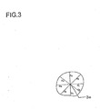
- the light source area designating unit 103a defines a specific outer frame that contacts the outline of the first extracted area and calculates the coordinate values (an x-coordinate value and a y-coordinate value) of a contact point at which the first extracted area and the outer frame contact each other. For instance, if a first extracted area 2a, such as that shown in FIG. 2 , has been extracted, the light source area designating unit 103a sets an outer frame 2b and calculates the coordinate values assumed at contact points 2c 2d, 2e, and 2f at which the first extracted area 2a and the outer frame 2b are in contact.
- the light source area designating unit 103a stores the areal size, the gravitational center position coordinate values, the coordinate values of the contact points at which the area and the outer frame are in contact and the distances from the gravitational center to the area edge having been calculated as described above into memory.
- An area extracted as described above is to be referred to as a second extracted area, so as to distinguish it from the first extracted area mentioned earlier.
- the light source area designating unit 103a calculates the areal size and the coordinate values (an x-coordinate value and a y-coordinate value) of the gravitational center position of each second extracted area it has extracted.
- the light source area designating unit 103a stores the areal size, the gravitational center position coordinate values, and the distances from the gravitational center to the area edge having been calculated as described above into memory.
- a single extracted area 2a may be present, as shown in FIG. 4A , or a plurality of first extracted areas 2a may be present as shown in FIG. 4B .
- the light source area designating unit 103a in the embodiment designates a light source area through different methods adopted for a second extracted area 4a containing a single first extracted area 2a and a second extracted area 4a containing a plurality of first extracted areas 2a.
- While a plurality of second extracted areas may have been extracted from the image, as described earlier, an explanation is given in reference to the embodiment on the processing executed to determine whether or not a given second extracted area 4a is to be designated as a light source area. Namely, if a plurality of second extracted areas 4a has been extracted, a decision as to whether or not each of the second extracted areas 4a should be designated as a light source area can be made simply by executing the processing described below for the individual second extracted areas 4a.
- a second extracted area 4a containing a single first extracted area 2a is likely to have a high degree of independence as a light source area and is, therefore, judged to be a light source area unless its shape is skewed.
- the light source area designating unit 103a makes the decision as to whether or not to designate the second extracted area 4a as a light source area as expressed in (2) and (3) below based upon the distances b i calculated along the eight directions extending from the gravitational center to the edge of the area.
- max(b i ) represents the largest value among b 1 through b 8
- min(b i ) represents the smallest value among b 1 through b 8 .
- the light source area designating unit 103a designates the second extracted area 4a as a light source area, whereas if the condition set forth in expression (3) is satisfied, it does not designate the second extracted area 4a as a light source area.
- the light source area designating unit 103a designates the gravitational center position of the first extracted area present inside the second extracted area as a light source position.
- the gravitational center G is designated as the light source position and a star is drawn by using bright beams extending along a plurality of directions from the starting point set at the gravitational center G, without drawing a star with bright beams extending along a plurality of directions from a starting point set at another gravitational center g i .
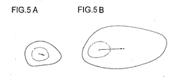
- the position of the gravitational center g B of B and the position of the extracted gravitational center G should not be set apart from each other over a significant distance, as indicated in FIG. 5A .
- the two positions are set apart by a significant distance, as indicated in FIG. 5B .
- the accuracy of the decision indicating that B is a light source area is judged in the embodiment. More specifically, if the distance between G and g B is beyond an allowable range, the light source area designating unit 103a judges that the decision indicating that B is a light source area is inaccurate. If, on the other hand, the distance between G and g B is within the allowable range, it judges at the decision indicating that B is a light source area is accurate.
- the light source area designating unit 103a judges that the decision indicating that B is a light source area is inaccurate if the distance between G and g B satisfies the condition set forth in expression (4) below, but judges that the decision is accurate if the condition is not satisfied.
- the light source area designating unit 103a makes a decision based upon expressions (5) and (6) below as to whether or not to designate B as a light source area. If the condition set forth in either expression (5) or expression (6) is satisfied, the light source area designating unit 103a does not designate B as a light source area, but it designates B as a light source area if neither of the conditions set forth in expressions (5) and expression (6) is satisfied.
- the light source area designating unit 103a is able to designate a light source area and a light source position within the image with superior accuracy.
- the star size determining unit 103b determines the size of the star to be drawn from the starting point set at the light source position designated by the light source area designating unit 103a as described above, i.e., determines the width and the length of bright beams. It is preferable that the bright beam width be determined in correspondence to the areal size S of the light source area and the range of the light source area.
- width_limit a specific upper limit value for the bright beam width (width) to be drawn in the light source area. Unless such an upper limit is set for the bright beam width to be drawn in a relatively small image, wide bright beams, not in keeping with the image size, may be drawn. For this reason, the upper limit value (width_limit) should be selected by also taking into consideration the image size.
- a lower limit value (Min_width) for to the bright beam width (width) should also be set.
- the lower limit value (Min_width) may be set to, for instance, 3 [pixels] .
- the bright beam width (width) should assume an odd number value, to assure symmetry relative to the central axis of the star.
- the star size determining unit 103b determines the star size as explained below.
- the star size determining unit 103b selects the upper limit value (width_limit) [pixels] to the bright beam width by applying conditional expressions in (7) through (9) below to the image size W [pixels] x H [pixels].
- the star size determining unit 103b calculates an assumed radius (Temp_R) as expressed in (10) below based upon the areal size S of the light source area.
- Temp_R S ⁇
- the star size determining unit 103b calculates an assumed width (Temp_width) [pixels] to be used to determine the bright beam width, as expressed in (11) below.
- Temp_width 2 ⁇ min min b i , Temp_R
- the star size determining unit 103b sets the bright beam width (width) to the lower limit value (Min_width) if the calculated width (Temp_width) is smaller than the bright beam width lower limit value (Min_width). If, on the other hand, the calculated width (Temp_width) is greater than the bright beam width upper limit value (width_limit), it sets the bright beam width (width) to the bright beam width upper limit value (width_limit), as indicated in expression (13) below.
- the star size determining unit 103b rounds off the value of the calculated width (Temp_width) to an integral value. If the integral value is an odd number, the integral value is directly designated as the bright beam width (width), whereas if the integral value is an even number, the value obtained by adding 1 to the integral value is designated as the bright beam width (width).
- the first term (min (W, H)/ 20) represents the minimum bright beam length (Min_Length) corresponding to the image size and ⁇ represents a parameter used to correct the bright beam length in correspondence to the bright beam width as mentioned above.
- the star color determining unit 103c determines the color of the star where bright beams are to be drawn from the starting point set at the light source position designated through the processing executed by the light source area designating unit 103a as explained earlier.
- the color assumed at the center of a light source area within an image is invariably white, irrespective of the color of the light source. This means that the R, G and B values are all close to 255 and that the R, G and B values are not the best information to be used when determining the star color.
- the star color is determined based upon the color information provided at an outer position in the designated light source area, i.e., at a point set apart from the gravitational center by a specific distance, is explained.
- the star color determining unit 103c may determine the color of the star by using the color information provided at a point within an outer area 6c, instead of a central area 6b in the light source area 6a shown in FIG. 6 .
- the star color determining unit 103c may execute the following processing.
- the star color determining unit 103c scans the light source area along the eight directions extending from the gravitational center of the light source area, i.e., from the gravitational center g B of the second extracted area described earlier, in the upward direction, the downward direction, to the left, to the right and in the diagonal directions, to locate points each satisfying the condition set forth in either expression (16) or expression (17), so as to extract one eligible point in correspondence to each direction, i.e., a total of eight points.
- the star color determining unit 103c calculates the eight points thus extracted for their hue circle angle distribution and eliminates any point far off the hue circle angle distribution. The star color determining unit 103c then determines the star color (Init_R, Init_G, Init_B) based upon the average of the hue circle angles of the remaining points.
- the star drawing unit 103d draws a star in the color having been determined by the star color determining unit 103c by using bright beams with the width and the length having been determined by the star size determining unit 103b extending from the starting point set at the light source position having been designated by the light source area designating unit 103a.
- the star drawing unit 103d in the embodiment executes processing so as to draw a more natural looking star by reproducing a phenomenon that would manifest if the light source was photographed with an actual star filter.
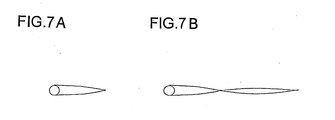
- FIG. 7A and FIG. 7B schematically illustrates how a star in an image photographed by using a star filter may become attenuated. For purposes of simplification of the illustration, FIG. 7A and FIG. 7B only shows a single bright beam extending to the right from the light source position in a star formed at the light source area.
- the star drawing unit 103d in the embodiment makes a decision as to whether to draw the star through simple attenuation or through cyclical attenuation based upon the bright beam length having been determined by the star size determining unit 103b, so as to achieve effects similar to those realized by photographing an image with a star filter.
- the bright beams in a star formed in an image photographed by using a star filter become narrower as the distance from the light source position increases, as shown in FIG. 7A and FIG. 7B .
- a star drawn by using a bright beam extending to the right from the light source position and sustaining the bright beam width (width) having been determined by the star size determining unit 103b from the starting point over the full bright beam length (length), as shown in FIG. 8A would not look natural.
- the star drawing unit 103d in the embodiment instead draws a star by using a bright beam with the pixel row drawn on the central axis of the star assuming a length equal to the calculated bright beam length (length), but the pixel rows of the bright beam drawn above and below the pixel row on the central axis parallel to the pixel row drawn on the central axis assuming smaller lengths further away from the central axis, so that the bright beam becomes narrower as the distance from the light source position increases, as illustrated in FIG. 8B .
- the star drawing unit 103d adjusts the attenuation processing depending upon whether the star color having been determined by the star color determining unit 103c is white, so as to ensure that the star includes rainbow colors in the bright beams.
- the following is a description of a specific example of processing that may be executed by the star drawing unit 103d.
- the star drawing unit 103d makes a decision as to whether or not the color of the star to be drawn is white.
- the star color (Init_R, Init_G, Init_B) satisfies the condition expressed in (18) below, the star color is judged to be white, whereas if it does not satisfy the condition, the star is assumed to be a color other than white.
- the star drawing unit 103d executes the star drawing processing based upon the star color having been determined.
- the drawing processing executed when the star color is other than white is now explained.
- a specific example of the processing executed to draw a bright beam extending from the light source position to the right in the star, as shown in FIG. 7A and FIG. 7B is described. Since bright beams extending along other directions (e.g., upward, downward and to the left), too, can be drawn along the specific directions by executing processing similar to that explained below, a repeated explanation is not provided.
- the star drawing unit 103d determines through calculation the exact pixel range, ranging above and below the central axis of the star, over which the bright beam needs to be drawn, as expressed in (19) below.
- n represents the number of pixel rows present above and below the central axis of the star, over which the bright beam needs to be drawn.
- n width - 1 / 2
- width 5 in the example presented in FIG. 8A and FIG. 8B and, in this case, n is calculated to be 2, since the bright beam needs to be drawn over two pixel rows above and below the central axis of the star.
- the star drawing unit 103d calculates the range over which the bright beam needs to be drawn, represented by a specific number of pixel rows present above and below the central axis of the star.
- the star drawing unit 103d will need to calculate the range over which the bright beam is to be drawn, represented by a specific number of pixel rows present to the left and to the right of the central axis of the star.
- the star drawing unit 103d calculates the length to be assumed for the pixel row in the bright beam, to be drawn on the central axis of the star and the length to be assumed for each pixel row in the bright beam, to be drawn above or below the central axis.
- end 0 indicates the length of the pixel row in the bright beam to be drawn on the central axis of the star and end 1 indicates the pixel row length assumed for both the pixel row in the bright beam to be drawn parallel to the central axis at the first position above the central axis and a pixel row in the bright beam to be drawn parallel to the central axis at a first position below the central axis.
- end 2 indicates the pixel row length assumed for both the pixel row in the bright beam to be drawn parallel to the central axis at a second position above the central axis and a pixel row in the bright beam to be drawn parallel to the central axis at a second position below the central axis
- end n indicates the pixel row length assumed for the pixel rows in the bright beam to be drawn parallel to the central axis at nth positions above and below the central axis.
- end k length - L / 2 ⁇ k - 1 / n
- the star drawing unit 103d determines whether to draw the star with simple attenuation or with cyclical attenuation, as described earlier. More specifically, it makes the decision as expressed in (22) and (23) below. Length ⁇ 3 ⁇ Min_Length ⁇ simple attenuation Length ⁇ 3 ⁇ Min_Length ⁇ cyclical attenuation
- Y_br Min_Length + max a 1 + L / 3
- Y_MAX, Y_MID1, Y_MID2, Y_MIN1 and Y_MIN2 in FIG. 9 are parameters upon which the bright beam attenuation is dependant and they may be respectively set too, for instance, 250, 200, 150, 80 and 30.
- a function indicating the attenuation of the intensity in the pixel row in the bright beam to be drawn parallel to the central axis at the kthposition from the central axis should be determined so that the curve representing the function passes through two points, i.e., (Y_br, Y_MID1 - ((Y_MID1 - Y_MID2) / n) ⁇ k) and (end k , Y_MIN1 - ((Y_MIN1 - Y_MIN2) / n) ⁇ k).
- the RGB values (Cross_R(x), Cross_G(x), Cross_B(x)) at position x in each pixel row included in the bright beam are obtained by first determining color difference values Cr and Cb in the YCbCr color space based upon (Init_R, Init_G, Init_B) and then converting (Y(x), Cb, Cr) to (Cross_R(x), Cross_G(x), Cross_B(x)).
- Data in the RGB color space are converted to YCbCr color space as expressed in (29) through (31) below, whereas data in the YCbCr color space are converted to the RGB color space by using conversion expressions that are a reversal of those in (29) through (31).
- Cross_R(x), Cross_G(x) and Cross_B(x) having been calculated that is smaller than 0 is corrected to 0, whereas any of Star_R(x), Star_G(x) and Star_B(x) with a value greater than 255 is corrected to 255.
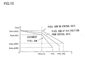
- a mixing ratio Ratio(x) at which the pixel values (R, G, B) in the input image and the (Cross_R(x), Cross_G(x), Cross_B(x)) values are to be mixed is determined, with the pixel values (R(x), G(x), B(x)) at position x calculated as expressed in (32) below.
- R x , G x , B x 1.0 - Ratio x ⁇ R ⁇ G ⁇ B + Ratio x ⁇ Cross_R x , Cross_G x , Cross_B x
- the mixing ratio Ratio (x) is a linear function assuming a divergence point at Ratio_br as shown in FIG. 10 .
- Ratio_MAX 1.0
- Ratio_MID 0.80
- Ratio_MIN1 0.40
- Ratio_MIN2 0.20
- the specific Ratio(x) for the pixel row in the bright beam to be drawn parallel to the central axis at the kth position from the central axis is written as a linear expression represented by a curve passing through two points (Ratio_br, Ratio_MAX - ((Ratio_MAX - Ratio_MID) / n) ⁇ k) and (end k , Ratio_MIN1 - ((Ratio_MIN1 - Ratio_MIN2) / n) ⁇ k).
- E k and F k are defined as expressed in (33) and (34), the linear expression in the range 0 ⁇ x ⁇ Ratio_br is written as in (35) below and the linear expression in the range Ratio_br ⁇ x ⁇ end k is written as in (36) below.
- E k - Ratio_MID ⁇ 1 - Ratio_MID ⁇ 2 n ⁇ k / Ratio_br
- F k Ratio_MID ⁇ 1 - Ratio_MID ⁇ 1 - Ratio_MID ⁇ 2 n ⁇ k - Ratio_MAX + Ratio_MAX - Ratio_MID n ⁇ k / end k - Ratio_br
- the star drawing unit 103d calculates pixel values (R(x), G(x), B(x)) at position x by using expression (32) presented earlier and then is able to draw the star in a color other than white through simple attenuation by drawing bright beams extending from the starting point set at the light source position in the image having been designated by the light source area designating unit 103a.
- Y_MAX, Y_MID1, Y_MID2, Y_LOC_MINI1, Y_LOC_MINI2, Y_MIN1 and Y_MIN2 may be respectively set to 250, 200, 180, 100, 50, 40 and 20. It is assumed that Y_br1 is equal to length/3 and that Y_br2 is equal to length/2.
- the function Y(x) is set so that the intensity value Y becomes attenuated as expressed in a quadratic expression in the range 0 ⁇ x ⁇ Y_br1 and in the range Y_br1 ⁇ x ⁇ Y_br2 and as expressed in a linear expression in the range Y_br2 ⁇ x ⁇ end k .
- a function indicating the attenuation of the intensity in the pixel row in the bright beam to be drawn parallel to the central axis at the kth position from the central axis should be determined so that the curve representing the function passes through three points, i.e., (Y_br1, (Y_LOC_MID1 - ((Y_LOC_MID1 - Y_LOC_MID2) / n) ⁇ k), (Y_br2, Y_MID1 - ((Y_MID1 - Y_MID2) / n) ⁇ k) and (end k , Y_MIN1 - ((Y_MIN1 - Y_MIN2) / n) ⁇ k).
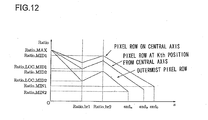
- the mixing ratio Ratio (x) is a linear function assuming divergence points at Ratio_br1 and Ratio_br2, as shown in FIG. 12 . It is assumed that the divergence points Ratio_br1 and Ratio_br2 in FIG. 12 are respectively equivalent to Y_br1 and Y_br2 mentioned earlier.
- Ratio_MAX, Ratio_MID1, Ratio_LOC_MID1, Ratio_MID2, Ratio_LOC_MID2, Ratio_MIN1 and Ratio_MIN2 may be respectively set to 1.0, 0.90, 0.80, 0.60, 0.40, 0.30 and 0.20.
- Ratio(x) for the pixel row in the bright beam to be drawn parallel to the central axis at the kth position from the central axis is written as a linear expression represented by curve passing through three points (Ratio_br1, Ratio_LOC_MID1 - ((Ratio_LOC_ MID1 - Ratio_LOC_MID2) / n) ⁇ k), (Ratio_br2, Ratio_MID1 - ((Ratio_MID1 - Ratio_MID2) / n) ⁇ k) and (end k , Ratio_MIN1 - ((Ratio_MIN1 - Ratio_MIN2) / n) ⁇ k).
- a white star in an image photographed by using an actual star filter includes rainbow colors in the bright beams.
- a star containing rainbow colors in the bright beams is formed as the hue H at position x changes cyclically.
- the star drawing unit 103d assumes temporary RGB values (Y(x), Y(x), Y(x)) at position x and obtains (H, S, V) by converting the R, G and B values in the HSV color space.
- H(x), S, H) with H(x) expressed in (49) below replacing H are converted to R, G and B values and these R, G and B values are designated as (Cross_R(x), Cross_G(x), Cross_B(x)) at position x.
- H x sin 3 length ⁇ 2 ⁇ ⁇ x
- the star drawing unit 103d calculates pixel values (R(x), G(x), B(x)) at position x by using expression (32) based upon (Cross_R(x), Cross_G(x), Cross_B(x) at position x calculated as described above and then draws a star with rainbow colors in the bright beams by drawing bright beams over the image, which extend from the starting point set at a light source position having been designated by the light source area designating unit 103a.
- the star drawing unit 103d also corrects the star to render an effect of light diffusion over the center of the star, i.e., over the area where the plurality of bright beams intersect one another. For instance, if bright beams extending along four directions, i.e., upward, downward, to the left and to the right, have been drawn to extend from the starting point set at the light source position through the processing described above, noticeable corners are present in the central area of the star, as shown in FIG. 13A . In the embodiment, as shown in FIG. 13B , a light diffusion effect is rendered over the central area of the star so as to achieve the effect similar to that in an image photographed by using an actual star filter.
- the star drawing unit 103d sets an xy coordinate system with the origin point O thereof set at the light source position and renders the light diffusion effect individually in the first quadrant, the second quadrant on the third quadrant and the fourth quadrant of the coordinate system as shown in FIG. 14 . While the following explanation focuses on the light diffusion effect rendered in the first quadrant, the light diffusion effect is rendered in the other quadrants through similar processing.
- the star drawing unit 103d designates an area under the curve where x ⁇ n and y ⁇ n are both true as a light diffusion effect target area.
- the star drawing unit 103d calculates the intensity value Y (x, y) as expressed in (51) below for each point (x, y) present within the designated area.
- Y x ⁇ y Y_MAX ⁇ 2 ⁇ n x 2 + y 2
- the star drawing unit 103d is able to render the light diffusion effect over the central area of the star by setting the mixing ratio Ratio (x, y) at which the input image and the intensity value Y (x, y) are to be mixed within the designated area to a predetermined value, e.g., 0.90 and then drawing the star based upon R, G and B values calculated for the individual pixels within the area, as expressed in (32) presented earlier.
- a predetermined value e.g. 0.90
- FIG. 15 presents a flowchart of the processing executed by the image processing apparatus in the embodiment.
- the processing in FIG. 15 is executed to draw a star in an image by the control device 103 based upon a program started up in response to a star drawing instruction issued by the user.
- step S10 the control device 103 reads star drawing target image data from the HDD 104 and then the operation proceeds to step S20.
- step S20 the light source area designating unit 103a executes the processing to be detailed later in reference to FIG. 16 to designate a light source area within the image.
- step S30 the star size determining unit 103b executes the processing to be detailed later in reference to FIG. 17 to determine the size of the star to be drawn in the image, i.e., the width and the length of the bright beams. Subsequently, the operation proceeds to step S40.
- step S40 the star color determining unit 103c executes the processing to be detailed later in reference to FIG. 18 to determine the color of the star to be drawn in the image. Then, the operation proceeds to step S50 in which the star drawing unit 103d draws a star in the size determined in step S30 and the color determined in step S40 at the light source position designated in step S20. The processing then ends.
- FIG. 16 presents a flowchart of the light source area designation processing executed in step S20.
- the operation then proceeds to step S23.
- step S23 the light source area designating unit 103a detects the relationship with which one type of area among the two types of areas having been extracted in steps S21 and S22 is contained in the other type of area. Namely, it determines whether or not the second extracted area contains a plurality of first extracted areas, as explained earlier.
- step S24 a decision is made as to whether or not the second extracted area is a light source area based upon the inclusive relationship between the gravitational center of the second extracted area and the gravitational center of each first extracted area present in the second extracted area and the ratio of the areal size of the second extracted area and the areal size of the first extracted area present in the second extracted area and, based upon the results of the decision-making, a light source area is designated in the image.
- the operation then returns to the processing shown in FIG. 15 .
- FIG. 17 presents a flowchart of the star size determining processing executed in step S30.
- the star size determining unit 103b determines the lower limit (Min_width) to the bright beam width based upon the image size W [pixels] x H [pixels].
- the operation subsequently proceeds to step S32 in which the star size determining unit 103b calculates the lengths b i from the gravitational center of the light source area to specific points on the edge of the area, before the operation proceeds to step S33.
- step S33 the star size determining unit 103b calculates the assumed radius (Temp_R) based upon the areal size (S) of the light source area as expressed in (10). Subsequently, the operation proceeds to step S34 in which the star size determining unit 103b determines the bright beam width based upon the relationship between the value of the assumed width (Temp_width) calculated as expressed in (11) and the lower limit (Min_width) value of the bright beam width relative to each other. The operation then proceeds to step S35.
- step S35 the star size determining unit 103b calculates the minimum bright beam length in correspondence to the image size W [pixels] x H [pixels]. The operation then proceeds to step S36 in which the star size determining unit 103b calculates the bright beam length (length) as expressed in (15) mentioned earlier. The operation then returns to the processing shown in FIG. 15 .
- FIG. 18 presents a flowchart of the star color determining processing executed in step S40.
- the star color determining unit 103c scans the light source area for points at which the condition set forth in either expression (16) or expression (17) is satisfied, along eight directions running from the gravitational center of the light source area, i.e., upward, downward, to the left, to the right and along the diagonals, in order to obtain color information from an outer area of the light source area, i.e., color information sampled at points present within the outer area 6c in FIG. 6 .
- the star color determining unit extracts one point satisfying the condition along each direction, i.e., a total of eight points.
- step S42 in which the star color determining unit 103c calculates the distribution of the hue circle angles of the eight extracted points, before the operation proceeds to step S43.
- step S43 any point, the hue circle angle of which is far off the distribution is eliminated and the star color (Init_R, Init_G, Init_B) is determined based upon the average of the hue circle angles assumed at the remaining points. The operation then returns to the processing shown in FIG. 15 .
- FIG. 19 presents a flowchart of the star drawing processing executed in step S50.
- the star drawing unit 103d makes a decision as to whether or not the bright beam length (length) is equal to or greater than a specific value. If an affirmative decision is made, the operation proceeds to step S52 in which the star drawing unit 103d makes a decision as to whether or not the star color is white. If a negative decision is made, the operation proceeds to step S53 in which the star drawing unit 103d draws a cyclically attenuating star in the YCbCr color space as described earlier and then the operation proceeds to step S55. In step S55, the star drawing unit 103d renders the diffusion effect over the central area of the star before the operation returns to the processing shown in FIG. 15 .
- step S52 If, on the other hand, an affirmative decision is made in step S52, the operation proceeds to step S54 in which the star drawing unit 103d draws a cyclically attenuating star in the HSV color space, before the operation proceeds to step S55. The operation then returns to the processing shown in FIG. 15 .
- step S51 the operation proceeds to step S51.
- step S56 the star drawing unit 103d makes a decision as to whether or not the star color is white. If a negative decision is made, the operation proceeds to step S57 in which the star drawing unit 103d draws a star that is attenuated through simple attenuation in the YCbCr color space as described earlier and then the operation proceeds to step S55. Subsequently, the operation returns to the processing shown in FIG. 15 .
- step S56 If an affirmative decision is made in step S56, the operation proceeds to step S58 in which the star drawing unit 103d draws a star that is attenuated through simple attenuation in the HSV color space as described earlier and then the operation proceeds to step S55. Subsequently, the operation returns to the processing shown in FIG. 15 .
- the image processing apparatus 100 may be, for instance, a personal computer.
- the image processing program product according to the present invention may be provided in a recording medium 200 (e.g., a CD-ROM) or as a data signal transmitted through a communication network 400 (e. g. , the Internet) as shown in FIG. 20 .
- a personal computer 100 takes in the image processing program via a CD-ROM 200.
- the personal computer 100 has the capability to connect with a communication network 400.
- a computer 300 is a server that provides the program stored in a recording medium such as a hard disk.
- the computer 300 transmits the image processing program read out from the hard disk, embodied as a data signal on a carrier wave, to the personal computer 100 via the communication network 400.
- the image processing program can be distributed as a computer program product adopting any of various modes including the recording medium 200 and the data signal transmitted via the communication network 400.
Landscapes
- Physics & Mathematics (AREA)
- General Physics & Mathematics (AREA)
- Engineering & Computer Science (AREA)
- Theoretical Computer Science (AREA)
- Image Processing (AREA)
- Facsimile Image Signal Circuits (AREA)
- Image Analysis (AREA)
- Processing Or Creating Images (AREA)
Applications Claiming Priority (1)
| Application Number | Priority Date | Filing Date | Title |
|---|---|---|---|
| JP2007150545A JP4985117B2 (ja) | 2007-06-06 | 2007-06-06 | 画像処理プログラム、および画像処理装置 |
Publications (3)
| Publication Number | Publication Date |
|---|---|
| EP2015250A2 true EP2015250A2 (de) | 2009-01-14 |
| EP2015250A3 EP2015250A3 (de) | 2010-09-29 |
| EP2015250B1 EP2015250B1 (de) | 2012-03-14 |
Family
ID=40070555
Family Applications (1)
| Application Number | Title | Priority Date | Filing Date |
|---|---|---|---|
| EP08157732A Not-in-force EP2015250B1 (de) | 2007-06-06 | 2008-06-06 | Bildverarbeitungsprogrammprodukt und Bildverarbeitungsvorrichtung |
Country Status (4)
| Country | Link |
|---|---|
| US (1) | US8326044B2 (de) |
| EP (1) | EP2015250B1 (de) |
| JP (1) | JP4985117B2 (de) |
| AT (1) | ATE549702T1 (de) |
Families Citing this family (2)
| Publication number | Priority date | Publication date | Assignee | Title |
|---|---|---|---|---|
| CN102422322B (zh) * | 2009-05-11 | 2015-01-21 | 杜比实验室特许公司 | 用于在目标环境下在装置处再现来自源环境的图像的色貌的方法和设备 |
| JP5653665B2 (ja) * | 2010-07-05 | 2015-01-14 | オリンパスイメージング株式会社 | 画像処理装置、撮影装置、画像処理方法及び画像処理プログラム |
Citations (3)
| Publication number | Priority date | Publication date | Assignee | Title |
|---|---|---|---|---|
| EP1513103A2 (de) | 2003-08-11 | 2005-03-09 | Hitachi, Ltd. | Bildverarbeitungsssystem und Fahrzeugsteuerungssystem |
| JP2005092724A (ja) | 2003-09-19 | 2005-04-07 | Noritsu Koki Co Ltd | 輝線描画処理方法及び輝線描画処理プログラム |
| EP1837803A2 (de) | 2006-03-24 | 2007-09-26 | MobilEye Technologies, Ltd. | Vorderlicht-, Schlusslicht- und Straßenbeleuchtungsdetektion |
Family Cites Families (17)
| Publication number | Priority date | Publication date | Assignee | Title |
|---|---|---|---|---|
| US4045655A (en) * | 1973-10-15 | 1977-08-30 | Hitachi, Ltd. | Automatic cyto-screening device |
| JPH07113961B2 (ja) * | 1985-08-05 | 1995-12-06 | キヤノン株式会社 | 信号処理装置 |
| US5150422A (en) * | 1989-03-31 | 1992-09-22 | Dainippon Screen Mfg. Co., Ltd. | Method of and apparatus for inspecting conductive pattern on printed board |
| US5150452A (en) * | 1989-07-28 | 1992-09-22 | Megamation Incorporated | Method and apparatus for anti-collision and collision protection for multiple robot system |
| JP3350296B2 (ja) * | 1995-07-28 | 2002-11-25 | 三菱電機株式会社 | 顔画像処理装置 |
| DE69635101T2 (de) * | 1995-11-01 | 2006-06-01 | Canon K.K. | Verfahren zur Extraktion von Gegenständen und dieses Verfahren verwendendes Bildaufnahmegerät |
| US6658163B1 (en) * | 1998-04-02 | 2003-12-02 | Fuji Photo Film Co., Ltd. | Image processing method |
| US6724435B2 (en) * | 2001-08-06 | 2004-04-20 | Oplus Technologies Ltd. | Method for independently controlling hue or saturation of individual colors in a real time digital video image |
| JP2003058880A (ja) * | 2001-08-21 | 2003-02-28 | Noritsu Koki Co Ltd | クロスフィルタ処理方法、クロスフィルタ処理装置、クロスフィルタ処理プログラム、及びこれを記録するコンピュータ読み取り可能な記録媒体 |
| JP3958987B2 (ja) | 2002-03-25 | 2007-08-15 | 浜松ホトニクス株式会社 | フォトンカウンティングシステム及びフォトンカウンティング方法 |
| US7356190B2 (en) | 2002-07-02 | 2008-04-08 | Canon Kabushiki Kaisha | Image area extraction method, image reconstruction method using the extraction result and apparatus thereof |
| JP4210995B2 (ja) | 2003-09-19 | 2009-01-21 | ノーリツ鋼機株式会社 | 輝点検出方法及び輝点検出プログラム |
| KR100485594B1 (ko) * | 2004-08-26 | 2005-04-27 | (주) 넥스트칩 | 영상에서의 잡음을 제거하기 위한 잡음 처리 방법 및 그시스템 |
| JP2006140695A (ja) * | 2004-11-11 | 2006-06-01 | Konica Minolta Photo Imaging Inc | 撮像装置 |
| JP4677226B2 (ja) | 2004-12-17 | 2011-04-27 | キヤノン株式会社 | 画像処理装置及び方法 |
| JP4208858B2 (ja) * | 2005-05-11 | 2009-01-14 | キヤノン株式会社 | レイアウト処理方法およびレイアウト処理装置およびレイアウト処理プログラム |
| JP4635828B2 (ja) * | 2005-11-07 | 2011-02-23 | コニカミノルタホールディングス株式会社 | 撮像装置、画像処理装置、画像処理方法及び画像処理プログラム |
-
2007
- 2007-06-06 JP JP2007150545A patent/JP4985117B2/ja not_active Expired - Fee Related
-
2008
- 2008-06-06 AT AT08157732T patent/ATE549702T1/de active
- 2008-06-06 EP EP08157732A patent/EP2015250B1/de not_active Not-in-force
- 2008-06-06 US US12/155,641 patent/US8326044B2/en not_active Expired - Fee Related
Patent Citations (3)
| Publication number | Priority date | Publication date | Assignee | Title |
|---|---|---|---|---|
| EP1513103A2 (de) | 2003-08-11 | 2005-03-09 | Hitachi, Ltd. | Bildverarbeitungsssystem und Fahrzeugsteuerungssystem |
| JP2005092724A (ja) | 2003-09-19 | 2005-04-07 | Noritsu Koki Co Ltd | 輝線描画処理方法及び輝線描画処理プログラム |
| EP1837803A2 (de) | 2006-03-24 | 2007-09-26 | MobilEye Technologies, Ltd. | Vorderlicht-, Schlusslicht- und Straßenbeleuchtungsdetektion |
Also Published As
| Publication number | Publication date |
|---|---|
| JP2008305081A (ja) | 2008-12-18 |
| JP4985117B2 (ja) | 2012-07-25 |
| EP2015250B1 (de) | 2012-03-14 |
| ATE549702T1 (de) | 2012-03-15 |
| US8326044B2 (en) | 2012-12-04 |
| EP2015250A3 (de) | 2010-09-29 |
| US20090010532A1 (en) | 2009-01-08 |
Similar Documents
| Publication | Publication Date | Title |
|---|---|---|
| US8040389B2 (en) | Image processing method, image processing program and image processing apparatus for detecting object of an image | |
| US7358994B2 (en) | Image processing apparatus, image processing method, recording medium thereof, and program thereof | |
| EP1754191B1 (de) | Charakterisierung eines digitalen abbildungssystems | |
| US8774507B2 (en) | Image processing device and image processing method to calculate a color correction condition | |
| US20180053290A1 (en) | Method and apparatus for adjusting image brightness | |
| EP1638345A1 (de) | Verfahren zur berechnung von display-kenngrössen-korrekturdaten, programm zum berechnen von display-kenngrössen-korrekturdaten und einrichtung zum berechnen von display-kenngrössen-korrekturdaten | |
| JP2001506113A (ja) | 画像解像度強化のための適応形斜方向内挿 | |
| EP3582179A1 (de) | Bildverarbeitungsvorrichtung, bildverarbeitungsverfahren und bildverarbeitungsprogramm | |
| US20110007947A1 (en) | Subject position determination method, program product for determining subject position, and camera | |
| US12561783B2 (en) | Abnormality detection device, abnormality detection method, and abnormality detection system | |
| JP7383531B2 (ja) | 監視装置、監視システムおよび監視方法 | |
| JP4035688B2 (ja) | 偽色除去装置、偽色除去プログラム、偽色除去方法およびデジタルカメラ | |
| US6591010B1 (en) | System and method for image detection and qualification | |
| EP2015250A2 (de) | Bildverarbeitungsprogrammprodukt und Bildverarbeitungsvorrichtung | |
| JP4140519B2 (ja) | 画像処理装置、プログラムおよび記録媒体 | |
| US20030011566A1 (en) | Image processing apparatus, image processing method, providing medium and presentation system | |
| JP4662258B2 (ja) | 画像処理方法及び装置、デジタルカメラ装置、並びに画像処理プログラムを記録した記録媒体 | |
| KR100734935B1 (ko) | 화상의 영역분할 | |
| US20090074244A1 (en) | Wide luminance range colorimetrically accurate profile generation method | |
| EP0849935A2 (de) | Feststellung der Beleuchtungsfarbe | |
| US10728448B2 (en) | Image processing apparatus, image processing method and storage medium to obtain a color difference of an object | |
| US11403736B2 (en) | Image processing apparatus to reduce noise in an image | |
| JP4659354B2 (ja) | 画像処理方法および装置 | |
| CN112767869A (zh) | 一种显示面板的显示效果的评价方法及装置 | |
| US12555348B2 (en) | Video processing apparatus, method for controlling the same, and non-transitory computer-readable storage medium |
Legal Events
| Date | Code | Title | Description |
|---|---|---|---|
| PUAI | Public reference made under article 153(3) epc to a published international application that has entered the european phase |
Free format text: ORIGINAL CODE: 0009012 |
|
| AK | Designated contracting states |
Kind code of ref document: A2 Designated state(s): AT BE BG CH CY CZ DE DK EE ES FI FR GB GR HR HU IE IS IT LI LT LU LV MC MT NL NO PL PT RO SE SI SK TR |
|
| AX | Request for extension of the european patent |
Extension state: AL BA MK RS |
|
| RAP1 | Party data changed (applicant data changed or rights of an application transferred) |
Owner name: NIKON CORPORATION |
|
| PUAL | Search report despatched |
Free format text: ORIGINAL CODE: 0009013 |
|
| AK | Designated contracting states |
Kind code of ref document: A3 Designated state(s): AT BE BG CH CY CZ DE DK EE ES FI FR GB GR HR HU IE IS IT LI LT LU LV MC MT NL NO PL PT RO SE SI SK TR |
|
| AX | Request for extension of the european patent |
Extension state: AL BA MK RS |
|
| RIC1 | Information provided on ipc code assigned before grant |
Ipc: G06T 5/00 20060101AFI20081208BHEP Ipc: G06T 11/00 20060101ALI20100825BHEP |
|
| 17P | Request for examination filed |
Effective date: 20110325 |
|
| AKX | Designation fees paid |
Designated state(s): AT BE BG CH CY CZ DE DK EE ES FI FR GB GR HR HU IE IS IT LI LT LU LV MC MT NL NO PL PT RO SE SI SK TR |
|
| 17Q | First examination report despatched |
Effective date: 20110511 |
|
| REG | Reference to a national code |
Ref country code: DE Ref legal event code: R079 Ref document number: 602008014068 Country of ref document: DE Free format text: PREVIOUS MAIN CLASS: G06T0005000000 Ipc: G06T0007000000 |
|
| GRAP | Despatch of communication of intention to grant a patent |
Free format text: ORIGINAL CODE: EPIDOSNIGR1 |
|
| RIC1 | Information provided on ipc code assigned before grant |
Ipc: G06T 5/00 20060101ALI20111010BHEP Ipc: G06T 11/00 20060101ALI20111010BHEP Ipc: G06T 7/00 20060101AFI20111010BHEP |
|
| GRAS | Grant fee paid |
Free format text: ORIGINAL CODE: EPIDOSNIGR3 |
|
| GRAA | (expected) grant |
Free format text: ORIGINAL CODE: 0009210 |
|
| AK | Designated contracting states |
Kind code of ref document: B1 Designated state(s): AT BE BG CH CY CZ DE DK EE ES FI FR GB GR HR HU IE IS IT LI LT LU LV MC MT NL NO PL PT RO SE SI SK TR |
|
| REG | Reference to a national code |
Ref country code: GB Ref legal event code: FG4D |
|
| REG | Reference to a national code |
Ref country code: AT Ref legal event code: REF Ref document number: 549702 Country of ref document: AT Kind code of ref document: T Effective date: 20120315 Ref country code: CH Ref legal event code: EP |
|
| REG | Reference to a national code |
Ref country code: IE Ref legal event code: FG4D |
|
| REG | Reference to a national code |
Ref country code: DE Ref legal event code: R096 Ref document number: 602008014068 Country of ref document: DE Effective date: 20120510 |
|
| REG | Reference to a national code |
Ref country code: NL Ref legal event code: VDEP Effective date: 20120314 |
|
| PG25 | Lapsed in a contracting state [announced via postgrant information from national office to epo] |
Ref country code: NO Free format text: LAPSE BECAUSE OF FAILURE TO SUBMIT A TRANSLATION OF THE DESCRIPTION OR TO PAY THE FEE WITHIN THE PRESCRIBED TIME-LIMIT Effective date: 20120614 Ref country code: LT Free format text: LAPSE BECAUSE OF FAILURE TO SUBMIT A TRANSLATION OF THE DESCRIPTION OR TO PAY THE FEE WITHIN THE PRESCRIBED TIME-LIMIT Effective date: 20120314 Ref country code: HR Free format text: LAPSE BECAUSE OF FAILURE TO SUBMIT A TRANSLATION OF THE DESCRIPTION OR TO PAY THE FEE WITHIN THE PRESCRIBED TIME-LIMIT Effective date: 20120314 |
|
| LTIE | Lt: invalidation of european patent or patent extension |
Effective date: 20120314 |
|
| PG25 | Lapsed in a contracting state [announced via postgrant information from national office to epo] |
Ref country code: FI Free format text: LAPSE BECAUSE OF FAILURE TO SUBMIT A TRANSLATION OF THE DESCRIPTION OR TO PAY THE FEE WITHIN THE PRESCRIBED TIME-LIMIT Effective date: 20120314 Ref country code: LV Free format text: LAPSE BECAUSE OF FAILURE TO SUBMIT A TRANSLATION OF THE DESCRIPTION OR TO PAY THE FEE WITHIN THE PRESCRIBED TIME-LIMIT Effective date: 20120314 Ref country code: GR Free format text: LAPSE BECAUSE OF FAILURE TO SUBMIT A TRANSLATION OF THE DESCRIPTION OR TO PAY THE FEE WITHIN THE PRESCRIBED TIME-LIMIT Effective date: 20120615 |
|
| REG | Reference to a national code |
Ref country code: AT Ref legal event code: MK05 Ref document number: 549702 Country of ref document: AT Kind code of ref document: T Effective date: 20120314 |
|
| PG25 | Lapsed in a contracting state [announced via postgrant information from national office to epo] |
Ref country code: CY Free format text: LAPSE BECAUSE OF FAILURE TO SUBMIT A TRANSLATION OF THE DESCRIPTION OR TO PAY THE FEE WITHIN THE PRESCRIBED TIME-LIMIT Effective date: 20120314 |
|
| PG25 | Lapsed in a contracting state [announced via postgrant information from national office to epo] |
Ref country code: SE Free format text: LAPSE BECAUSE OF FAILURE TO SUBMIT A TRANSLATION OF THE DESCRIPTION OR TO PAY THE FEE WITHIN THE PRESCRIBED TIME-LIMIT Effective date: 20120314 Ref country code: CZ Free format text: LAPSE BECAUSE OF FAILURE TO SUBMIT A TRANSLATION OF THE DESCRIPTION OR TO PAY THE FEE WITHIN THE PRESCRIBED TIME-LIMIT Effective date: 20120314 Ref country code: EE Free format text: LAPSE BECAUSE OF FAILURE TO SUBMIT A TRANSLATION OF THE DESCRIPTION OR TO PAY THE FEE WITHIN THE PRESCRIBED TIME-LIMIT Effective date: 20120314 Ref country code: PL Free format text: LAPSE BECAUSE OF FAILURE TO SUBMIT A TRANSLATION OF THE DESCRIPTION OR TO PAY THE FEE WITHIN THE PRESCRIBED TIME-LIMIT Effective date: 20120314 Ref country code: SI Free format text: LAPSE BECAUSE OF FAILURE TO SUBMIT A TRANSLATION OF THE DESCRIPTION OR TO PAY THE FEE WITHIN THE PRESCRIBED TIME-LIMIT Effective date: 20120314 Ref country code: BE Free format text: LAPSE BECAUSE OF FAILURE TO SUBMIT A TRANSLATION OF THE DESCRIPTION OR TO PAY THE FEE WITHIN THE PRESCRIBED TIME-LIMIT Effective date: 20120314 Ref country code: IS Free format text: LAPSE BECAUSE OF FAILURE TO SUBMIT A TRANSLATION OF THE DESCRIPTION OR TO PAY THE FEE WITHIN THE PRESCRIBED TIME-LIMIT Effective date: 20120714 Ref country code: RO Free format text: LAPSE BECAUSE OF FAILURE TO SUBMIT A TRANSLATION OF THE DESCRIPTION OR TO PAY THE FEE WITHIN THE PRESCRIBED TIME-LIMIT Effective date: 20120314 |
|
| PG25 | Lapsed in a contracting state [announced via postgrant information from national office to epo] |
Ref country code: SK Free format text: LAPSE BECAUSE OF FAILURE TO SUBMIT A TRANSLATION OF THE DESCRIPTION OR TO PAY THE FEE WITHIN THE PRESCRIBED TIME-LIMIT Effective date: 20120314 Ref country code: PT Free format text: LAPSE BECAUSE OF FAILURE TO SUBMIT A TRANSLATION OF THE DESCRIPTION OR TO PAY THE FEE WITHIN THE PRESCRIBED TIME-LIMIT Effective date: 20120716 |
|
| PLBE | No opposition filed within time limit |
Free format text: ORIGINAL CODE: 0009261 |
|
| STAA | Information on the status of an ep patent application or granted ep patent |
Free format text: STATUS: NO OPPOSITION FILED WITHIN TIME LIMIT |
|
| PG25 | Lapsed in a contracting state [announced via postgrant information from national office to epo] |
Ref country code: MC Free format text: LAPSE BECAUSE OF NON-PAYMENT OF DUE FEES Effective date: 20120630 Ref country code: DK Free format text: LAPSE BECAUSE OF FAILURE TO SUBMIT A TRANSLATION OF THE DESCRIPTION OR TO PAY THE FEE WITHIN THE PRESCRIBED TIME-LIMIT Effective date: 20120314 Ref country code: AT Free format text: LAPSE BECAUSE OF FAILURE TO SUBMIT A TRANSLATION OF THE DESCRIPTION OR TO PAY THE FEE WITHIN THE PRESCRIBED TIME-LIMIT Effective date: 20120314 Ref country code: NL Free format text: LAPSE BECAUSE OF FAILURE TO SUBMIT A TRANSLATION OF THE DESCRIPTION OR TO PAY THE FEE WITHIN THE PRESCRIBED TIME-LIMIT Effective date: 20120314 |
|
| REG | Reference to a national code |
Ref country code: CH Ref legal event code: PL |
|
| REG | Reference to a national code |
Ref country code: CH Ref legal event code: PL |
|
| 26N | No opposition filed |
Effective date: 20121217 |
|
| PG25 | Lapsed in a contracting state [announced via postgrant information from national office to epo] |
Ref country code: IT Free format text: LAPSE BECAUSE OF FAILURE TO SUBMIT A TRANSLATION OF THE DESCRIPTION OR TO PAY THE FEE WITHIN THE PRESCRIBED TIME-LIMIT Effective date: 20120314 |
|
| REG | Reference to a national code |
Ref country code: IE Ref legal event code: MM4A |
|
| REG | Reference to a national code |
Ref country code: DE Ref legal event code: R097 Ref document number: 602008014068 Country of ref document: DE Effective date: 20121217 |
|
| PG25 | Lapsed in a contracting state [announced via postgrant information from national office to epo] |
Ref country code: LI Free format text: LAPSE BECAUSE OF NON-PAYMENT OF DUE FEES Effective date: 20120630 Ref country code: CH Free format text: LAPSE BECAUSE OF NON-PAYMENT OF DUE FEES Effective date: 20120630 Ref country code: ES Free format text: LAPSE BECAUSE OF FAILURE TO SUBMIT A TRANSLATION OF THE DESCRIPTION OR TO PAY THE FEE WITHIN THE PRESCRIBED TIME-LIMIT Effective date: 20120625 Ref country code: IE Free format text: LAPSE BECAUSE OF NON-PAYMENT OF DUE FEES Effective date: 20120606 |
|
| PG25 | Lapsed in a contracting state [announced via postgrant information from national office to epo] |
Ref country code: MT Free format text: LAPSE BECAUSE OF FAILURE TO SUBMIT A TRANSLATION OF THE DESCRIPTION OR TO PAY THE FEE WITHIN THE PRESCRIBED TIME-LIMIT Effective date: 20120314 Ref country code: BG Free format text: LAPSE BECAUSE OF FAILURE TO SUBMIT A TRANSLATION OF THE DESCRIPTION OR TO PAY THE FEE WITHIN THE PRESCRIBED TIME-LIMIT Effective date: 20120614 |
|
| PG25 | Lapsed in a contracting state [announced via postgrant information from national office to epo] |
Ref country code: TR Free format text: LAPSE BECAUSE OF FAILURE TO SUBMIT A TRANSLATION OF THE DESCRIPTION OR TO PAY THE FEE WITHIN THE PRESCRIBED TIME-LIMIT Effective date: 20120314 |
|
| PG25 | Lapsed in a contracting state [announced via postgrant information from national office to epo] |
Ref country code: LU Free format text: LAPSE BECAUSE OF NON-PAYMENT OF DUE FEES Effective date: 20120606 |
|
| PG25 | Lapsed in a contracting state [announced via postgrant information from national office to epo] |
Ref country code: HU Free format text: LAPSE BECAUSE OF FAILURE TO SUBMIT A TRANSLATION OF THE DESCRIPTION OR TO PAY THE FEE WITHIN THE PRESCRIBED TIME-LIMIT Effective date: 20080606 |
|
| REG | Reference to a national code |
Ref country code: FR Ref legal event code: PLFP Year of fee payment: 9 |
|
| REG | Reference to a national code |
Ref country code: FR Ref legal event code: PLFP Year of fee payment: 10 |
|
| REG | Reference to a national code |
Ref country code: FR Ref legal event code: PLFP Year of fee payment: 11 |
|
| PGFP | Annual fee paid to national office [announced via postgrant information from national office to epo] |
Ref country code: GB Payment date: 20220428 Year of fee payment: 15 Ref country code: FR Payment date: 20220510 Year of fee payment: 15 Ref country code: DE Payment date: 20220505 Year of fee payment: 15 |
|
| P01 | Opt-out of the competence of the unified patent court (upc) registered |
Effective date: 20230517 |
|
| REG | Reference to a national code |
Ref country code: DE Ref legal event code: R119 Ref document number: 602008014068 Country of ref document: DE |
|
| GBPC | Gb: european patent ceased through non-payment of renewal fee |
Effective date: 20230606 |
|
| PG25 | Lapsed in a contracting state [announced via postgrant information from national office to epo] |
Ref country code: DE Free format text: LAPSE BECAUSE OF NON-PAYMENT OF DUE FEES Effective date: 20240103 Ref country code: GB Free format text: LAPSE BECAUSE OF NON-PAYMENT OF DUE FEES Effective date: 20230606 |
|
| PG25 | Lapsed in a contracting state [announced via postgrant information from national office to epo] |
Ref country code: FR Free format text: LAPSE BECAUSE OF NON-PAYMENT OF DUE FEES Effective date: 20230630 |