EP2015255A1 - Dispositif de détermination d'une image d'affichage - Google Patents
Dispositif de détermination d'une image d'affichage Download PDFInfo
- Publication number
- EP2015255A1 EP2015255A1 EP08008347A EP08008347A EP2015255A1 EP 2015255 A1 EP2015255 A1 EP 2015255A1 EP 08008347 A EP08008347 A EP 08008347A EP 08008347 A EP08008347 A EP 08008347A EP 2015255 A1 EP2015255 A1 EP 2015255A1
- Authority
- EP
- European Patent Office
- Prior art keywords
- detection
- distance
- line
- lines
- sensor
- Prior art date
- Legal status (The legal status is an assumption and is not a legal conclusion. Google has not performed a legal analysis and makes no representation as to the accuracy of the status listed.)
- Withdrawn
Links
Images


Classifications
-
- G—PHYSICS
- G06—COMPUTING OR CALCULATING; COUNTING
- G06T—IMAGE DATA PROCESSING OR GENERATION, IN GENERAL
- G06T11/00—Two-dimensional [2D] image generation
- G06T11/20—Drawing from basic elements
- G06T11/23—Drawing from basic elements using straight lines or curves
-
- B—PERFORMING OPERATIONS; TRANSPORTING
- B60—VEHICLES IN GENERAL
- B60Q—ARRANGEMENT OF SIGNALLING OR LIGHTING DEVICES, THE MOUNTING OR SUPPORTING THEREOF OR CIRCUITS THEREFOR, FOR VEHICLES IN GENERAL
- B60Q9/00—Arrangement or adaptation of signal devices not provided for in one of main groups B60Q1/00 - B60Q7/00, e.g. haptic signalling
- B60Q9/002—Arrangement or adaptation of signal devices not provided for in one of main groups B60Q1/00 - B60Q7/00, e.g. haptic signalling for parking purposes, e.g. for warning the driver that his vehicle has contacted or is about to contact an obstacle
- B60Q9/007—Arrangement or adaptation of signal devices not provided for in one of main groups B60Q1/00 - B60Q7/00, e.g. haptic signalling for parking purposes, e.g. for warning the driver that his vehicle has contacted or is about to contact an obstacle providing information about the distance to an obstacle, e.g. varying sound
Definitions
- the invention is in the field of automotive technology, more precisely in the field of driver assistance systems, which assist the driver in modern vehicles to master increasingly complex traffic and driving situations.
- driver assistance systems for example, speed and distance warning and control systems, braking and stability assistance, lane departure systems, distance warning systems and parking aids are known.
- the present invention is concerned with conveniently and clearly generating display images used for such systems.
- a device for distance measurement in which a plurality of distance sensors are provided, which can be operated in different ways in order to improve the quality of the measurements.
- the present invention has for its object to further improve such displays.
- Bezier curves are used in a manner known per se for generating a smooth, clear line which adequately represents any existing objects.
- Bezier curves have long been known in the making of graphics from numerical mathematics. They use the so-called Berstein polynomials to represent smooth curves are determined by a few parameters and easy to handle.
- Bezier curves of different degrees depending on the number of existing interpolation points There are Bezier curves of different degrees depending on the number of existing interpolation points.
- a number of curve points, in the present case object positions are given, through which the resulting curve passes as well as curve edge points at which it ends.
- Each object position is assigned two Bezier object interpolation points, whose position can be chosen basically different, whereby the shape of the curve changes while maintaining the predetermined curve points.
- the idea of the invention is based on the assumption that, for a plurality of distance sensors distributed on a vehicle, there are in each case individual distance detection values which define concrete curve points. It has been found that the arrangement of the object support points and the curve edge points according to the invention leads to clear and realistic representations of each detected obstacles and limitations.
- the inventive method is independent of the type and number of sensors that can be used for the distance detection.
- ultrasonic transducers Basically, the use of ultrasonic transducers is possible, however, radar and lidar systems can also be used, wherein the sensors need not be assigned individually to the detection lines according to the invention, for example, when cross echoes are evaluated or the like.
- the device for determining a display image has a first memory device for storing the distance detection values and also for Storage of wall parameters that may be present if certain limits of the distance from the vehicle are undershot for individual detection lines.
- the sensor boundary points are or are deposited, which serve as boundary points in the calculation of corresponding Bezier curves.
- a Bezier calculation module is provided for calculating the respective Bezier curve for a group of detection lines.
- the vehicle is initially shown schematically as viewed from above, with a detection area of sensors located in front of, behind or in addition to the vehicle, each generally forming a part of a sector of a circle bounded by an inner and outer detection boundary becomes. Obstacles located on either side of and beyond the detection boundary line are not detected by the transducers and not displayed in the display system.
- the Bezier curve produced by the method according to the invention represents objects or obstacles protruding therefrom within the circle sector described.
- any resulting steps or inaccuracies caused by the number of sensors or detection lines should be kept as inconspicuous as possible in order to present the contour of an obstacle as smoothly and realistically as possible.
- an advantageous embodiment of the invention provides that, if at least three adjacent detection lines associated object positions are taking into account certain maximum deviations on a straight line, the respective detection lines each a wall parameter (wall flag) is assigned, that is checked whether adjacent detection lines each one wall parameter is assigned and that in this case the two object positions assigned to the corresponding detection lines are connected to each other by a straight line or the one Object positions assigned support points are arranged directly on the respective detection line.
- a straight line as straight as possible should be generated.
- Such an object is best represented by a straight connection between any two or all object positions, or by a variant of the Bezier curve, in which the object interpolation points in the said area directly on the respective detection line or in their immediate vicinity, in particular on the object position, be placed.
- the remainder of the Bezier curve is completed according to the usual rules.
- an additional virtual side detection line is generated for realistically determining the display image outside the outer lateral detection line, to which a virtual object position and a wall parameter are assigned ,
- An outer lateral detection line is to be understood as meaning such a detection line, which is respectively directed to the surroundings of the vehicle in the front lateral area, where objects are also displayed where the vehicle passes close by.
- a wall parameter is also set in the detection line adjacent to the outer lateral detection line.
- a further advantageous embodiment of the invention provides that in the case that in each case with more than two immediately adjacent detection lines a wall parameter is set, the two outer object positions are set for the determination of the display image and at least one of the remaining object positions between the two outer object positions is disregarded.
- the display image can be improved by making the distance detection value of the adjacent one when the distance detection value of one detection line is smaller than the distance exceeding the detection value of this adjacent detection line and the difference exceeds a given threshold value Detection line is removed, with the corresponding sensor edge remains unchanged.
- the sensor detection angle of a detection line can also be determined as a function of available distance detection values.
- the sensor detection angle can be set individually, but also for all detection lines together.
- the sensor detection angle may be selected as a function of the amount of the difference of the present distance detection values, in particular the amount of the difference between two adjacent distance detection values. It is advantageous to individually or collectively select the sensor detection angle the smaller the difference, for example the average or minimum difference, of the present distance detection values is. This can in principle also apply to subgroups from the number of data entry lines.
- the Bezier curve is flattened by the widely spaced curve edge points, so that a smoother contour results.
- the sensor detection angles affect the resulting Bezier curve in that they are at their intersections with the outer, d. H. are determined by the motor vehicle farthest detection boundary line of the distance detection range, the respective sensor boundary points, wherein the respective outermost sensor boundary points of a group of detection lines form the curve boundary points of the Bezier curve.
- a further advantageous embodiment of the invention can also provide that, for each detection line for which there is a distance detection value, the distance of the individual object support points from the detection line is determined as a function of the distance detection values of the detection line and its detection line adjacent to the respective object support point.
- This idea allows the two object support points, which are each assigned to a detection line, to be arranged at different distances from the detection line, the distance in each case being dependent on the difference between the distance detection values of the two detection lines adjacent to the respective object support point.
- the distance detection values of adjacent detection lines differ greatly, the distance of the corresponding object interpolation point lying between the two detection lines would be very large from the associated detection line. If there is only a small difference between the distance detection values, the corresponding object interpolation point would be arranged relatively close to the detection line assigned to it.
- the distance of the object support points from the respectively associated detection lines can be proportional to the said differences of the distance detection values with a common proportionality constant for all distances, so that the calculation of the object interpolation points for all detection lines is simplified as a whole.
- a limitation in the determination of the distances of the object support points from the respective detection line can be provided by a minimum distance and a maximum distance.
- the position of the object support points along the detection line associated therewith is at the same level as the respective present object position.
- the object interpolation points along their respective detection line do not lie at the height of the object position but are displaced along the respective detection line such that the height of the object interpolation points of different detection lines are at least partially aligned becomes. It is assumed that the corresponding detection lines are at such an acute angle to each other that the positions of the object support points along the detection lines can be compared.
- the heights of the object support points along the respective detection lines can be adjusted to a common mean value.
- the invention can be advantageously designed with respect to temporal changes of the object detection, that the display image is determined repeatedly and that when changes in the distance detection values between a present display image and a subsequent determination in the determination only a part of the difference to the data of the present display image is taken into account.
- the timing may be periodic, but also dependent on the occurrence of changes.
- a newly calculated display image is less changed when changing measured values / distance detection values than would correspond to the changed measured values. This can be achieved for example by so-called damping factors by which a new display image is not based on the latest measured value, but an intermediate value between a previously existing measured value and a new measured value.
- damping factors by which a new display image is not based on the latest measured value, but an intermediate value between a previously existing measured value and a new measured value.
- each step approximates the value used in the newly calculated image to the actual measurement. In this way, the data underlying the current display image asymptotically approximate the actual measurement data. Individual outliers among the readings can be smoothed out by this procedure.
- the method can be configured by respectively forming the difference between the data underlying the previous display image and the current measured value, multiplying this difference by an attenuation factor smaller than 1, and adding the resulting correction value to the previously used measured data.
- the invention relates in addition to the described method also to a device for determining a display image according to claim 17 and to a driver assistance system with a sensor system for detecting and outputting distance detection values and optionally wall parameters and with a device according to claim 17.
- the corresponding sensor system can except The distance detection values also provide the wall parameters when the limit values of the individual detection lines are undershot.
- corresponding wall parameters can also be obtained in the device for determining the display image from the available distance detection values by calculation.
- integrating this feature into the sensor system helps to save time and expose alerts that are due to reduce object spacing faster and less error-prone.
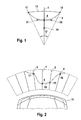
- FIG. 1 shows by way of example a detection line 1, which can indicate in a vehicle, for example, the direction in which a sensor for detecting objects is aligned with its detection cone.
- object positions of detected objects can be determined by means of a more complex system, for example via cross echoes.
- object positions which are determined on previously determined detection lines are advantageously considered, but these can also be determined from object positions only in the course of the method.
- an object position 8 whose coordinates are known in the system or can be determined, for example, from a distance detection value.
- the aim of the invention is to determine a Bezier curve, which is denoted by 9, by the object position 8 as well as by the curved edge points 10, 11.
- the curve edge points 10, 11 are given by the intersections of the sensor detection angle 12 with a detection limit line 13. However, curve edge points outside the detection range can also be specified.
- the sensor detection angle 12 is approximately symmetrical about the detection line 1, but is given in the angular size but independent of the detection physics only by the modeling in the determination of a Bezier curve. With the free choice of the sensor detection angle 12, the nature of the resulting Bezier curves can be set to be flatter at larger sensor detection angles, or steeper at narrower angles. For example, the sensor detection angles can be the same for all detection lines of a sensor group, but can also be selected individually.
- the detection limit line 13 is essentially given by the distance from the vehicle in which objects are still to be detected and displayed.
- object support points 37, 38 are shown, which serve to calculate the Bezier curve and whose positioning contributes to the appropriate design of the display image
- FIG. 1 to take a limit value 14 for object positions, indicating the distance from the motor vehicle, below which a wall parameter (Wall Flag) is set.
- the setting of the wall flag can be done either during the determination of the object distances in the sensors or also during the post-processing of the measured values in the context of the method according to the invention.
- wall flags is based on the idea that for larger objects, which are detected by several sensors or on several directly adjacent detection lines in approximately linear arrangement, the probability of a smooth contour, such as in a wall to which the Vehicle approaches, is particularly large, but at the same time measurement errors can occur, which can lead to a discontinuous or not even representation. For this reason, the system provides the option that in the case where two adjacent detection lines have corresponding object positions with set wall parameters, these object positions will not be connected by a mostly curved Bezier curve, but that curve will be on that part continues as a straight line. This generally results in a more realistic image of the detected object.
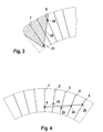
- FIG. 2 This circumstance is more accurate in the FIG. 2 in which the detection lines 1, 2, 3, 4 are given with corresponding object positions 8, 15, 16, 17 for the vehicle 18. If the object positions 8, 15, 16 were located approximately on a straight line, then wall flags would be set for the detection lines 1, 2 and 4 and the corresponding line between these object points would be represented as a straight line 19 or in this area would be the object line. Support points on the object position or placed close to this, which would lead to a very elongated, approximately straight design of the Bezier curve in this area. In the adjacent areas, the Bezier curve will continue in any case. However, such a procedure is advantageously provided only when there are several, in particular at least three object positions arranged on adjacent detection lines, for which wall parameters are respectively set.
- FIG. 3 the use of the wall flags in connection with obstacles located laterally in front of the vehicle, in particular walls, is shown in more detail.
- an additional, virtual side detection line 7 which does not correspond to any object detection in the system.
- an object position 21 is assumed, and in any case, a wall flag is set, resulting in the object positions 20 and 21 being connected by a straight line.
- the object position 21 can be selected individually such that the connecting straight line 22 has the desired direction, for example parallel to the vehicle, or a standard position can also be assumed.
- the shaded area in the figure can be colored, so that when viewing the display image on the left front side of the vehicle, the representation of a wall is formed.
- a wall flag can also be forcibly set on the next adjacent detection line in order to also create the straight connection to the object position 20 there with a suitable object position and thus to further improve the image.
- FIG. 4 is shown that in a plurality of object positions 8, 15, 23, 24, 25, for each of which a wall flag is set, according to an embodiment of the invention, not all object positions are connected by straight lines in pairs (dashed execution), but in this case, one or more of the object positions between the outermost object positions with wall flag, in the present case 8 and 25, can be neglected and only the outside can be connected by means of a straight line. This creates a clear contour of a displayed object in the detection field.
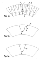
- FIGS. 5a-c show at a plurality of detection lines 1, 2, the respectively associated sensor detection angle 12 and detected object positions 8, 27 and a curve edge point 56th
- the Bezier curve 26 is calculated taking into account all object positions 8, 27, and in the lower part of the figure the Bezier curve 28 in which the corner points are also selected at the Bezier curve 26, namely as sensor boundaries of the corresponding detection lines 1, 2, but because of the large difference of the distance detection values of the object positions 8, 27, the peripheral and farther point 27 is disregarded in the calculation of the Bezier curve.
- the resulting Bezier curve 28 is more convincing due to the smoothed contour and is simplified in terms of the information content of the display image without disadvantages.
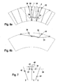
- FIGS. 6a, b show two detection lines 1, 2 with object positions 29, 30 and two variants 31, 32 of the determined Bezier curve as a function of the underlying sensor detection angles.
- the determination of the Bezier curve 31 is another sensor detection angle - dashed lines in the figure and designated by the reference numerals 33, 34 - used as the Bezier curve 32 in each case a narrower sensor detection angle with the curve edge points 35, 36 is used. In this way, the nature of the Bezier curve generated can be determined by the appropriate choice of sensor detection angles.
- the object support points can be arranged on an orthogonal 39 to the detection line 1.
- the distances d1, d2 may be determined taking into account the object positions 40, 41 of adjacent detection lines 2, 3, where d1, d2 may be proportional to the difference of corresponding distance detection values on the respective side of the detection line 1 with a predetermined proportionality factor , Again, under certain conditions, the shape of the Bezier curve can be improved.
- FIG. 8a It is shown that also the height of the object support points 37, 38 along the detection line 1 can be changed in consideration of the distance detection values of the detection lines 1, 2.
- the corresponding object support points can be shifted to the height of the respectively displayed points 44, 45 and thus be approximated to one another for adjacent detection lines 1, 2.
- the corresponding sensor detection angles can be chosen so large that they overlap one another - visible in the hatched area.
- c is additionally shown in the lower area that also individual bases along the respective detection line (in height) and / or in their distance perpendicular to the respective detection line can be selectively moved. Possible distributions of support points in the upper area of the figure are shown.
- FIG. 9 By way of example, a complete driver assistance system with a device for carrying out the method according to the invention, ie for generating a display image, is shown.
- Physical sensors 46, 47 are shown, by means of which with a sensor system 48 object positions are determined which lie on the given detection lines 1, 2, 3, 4, 5, 6. In addition, corresponding wall parameters can also be set in the system.
- the determined values are passed to the device 49 for carrying out the method, where the object positions or distance detection values are stored in a first memory device 50 and sensor boundary points are stored in a second memory device 51.
- one Bezier calculation module 52 one or more Bezier curves 53, 54 are determined which are integrated into the display image 55.
- the respective Bezier curves 53, 54 are each closed by a detection boundary line 13, so that closed and shaded by a simple graphics program, shaded areas shown in the figure arise that allow for a driver detecting obstacles in the detection range of the driver assistance system.
- the calculation unit can optionally be integrated into different systems. It can be part of the sensor system, part of the display system or even a separate unit.
- Corresponding systems can be provided both for the area in front of the vehicle and behind the vehicle.
- FIGS. 10a, b In the upper part, two detected object positions 15, 16 are shown, which can be used to dynamically generate detection lines 2, 3 on which these object positions lie. The further procedure can then be based on this data generated by the definition of detection angles, interpolation points and other parameters.
- FIGS. 11a, b show a method for setting wall parameters (wall flags), in which it is first determined whether at least three object positions of adjacent detection lines can be a straight line.
- wall parameters can be assigned to all corresponding object positions / detection lines.
- the object positions can then be connected in sections or in total by a straight line, or the corresponding object bases are placed without distance on the detection lines, in particular on the object position points themselves, then a Bezier curve to calculate. Due to the positioning of the support points, the resulting Bezier curve will assume a very straight, approximately straight shape in this area.
- the inventive method is prepared so that it can be used for changing configurations, in particular changing numbers of detection lines without manual parameterization.
Landscapes
- Engineering & Computer Science (AREA)
- Physics & Mathematics (AREA)
- General Physics & Mathematics (AREA)
- Theoretical Computer Science (AREA)
- Transportation (AREA)
- Human Computer Interaction (AREA)
- Mechanical Engineering (AREA)
- Traffic Control Systems (AREA)
- Measurement Of Optical Distance (AREA)
- Radar Systems Or Details Thereof (AREA)
Applications Claiming Priority (1)
| Application Number | Priority Date | Filing Date | Title |
|---|---|---|---|
| DE102007032698A DE102007032698B3 (de) | 2007-07-13 | 2007-07-13 | Verfahren zur Ermittlung eines Anzeigebildes |
Publications (1)
| Publication Number | Publication Date |
|---|---|
| EP2015255A1 true EP2015255A1 (fr) | 2009-01-14 |
Family
ID=39596557
Family Applications (1)
| Application Number | Title | Priority Date | Filing Date |
|---|---|---|---|
| EP08008347A Withdrawn EP2015255A1 (fr) | 2007-07-13 | 2008-05-02 | Dispositif de détermination d'une image d'affichage |
Country Status (4)
| Country | Link |
|---|---|
| US (1) | US7974783B2 (fr) |
| EP (1) | EP2015255A1 (fr) |
| JP (1) | JP2009020892A (fr) |
| DE (1) | DE102007032698B3 (fr) |
Cited By (2)
| Publication number | Priority date | Publication date | Assignee | Title |
|---|---|---|---|---|
| DE102014204652A1 (de) | 2014-03-13 | 2015-09-17 | Robert Bosch Gmbh | Verfahren und Vorrichtung zur Darstellung einer Fahrzeugumgebung eines Fahrzeuges |
| CN109532662A (zh) * | 2018-11-30 | 2019-03-29 | 广州鹰瞰信息科技有限公司 | 一种车距及碰撞时间计算方法及装置 |
Families Citing this family (16)
| Publication number | Priority date | Publication date | Assignee | Title |
|---|---|---|---|---|
| JP4703136B2 (ja) * | 2004-06-02 | 2011-06-15 | トヨタ自動車株式会社 | 線図形化処理装置 |
| DE102008064361A1 (de) * | 2008-12-22 | 2010-06-24 | Volkswagen Ag | Verfahren und Vorrichtung zur Visualisierung der direkten Umgebung eines Fahrzeugs |
| DE102009024062A1 (de) * | 2009-06-05 | 2010-12-09 | Valeo Schalter Und Sensoren Gmbh | Vorrichtung und Verfahren zur Anzeige von Objekten in einer Fahrzeugumgebung |
| FR2981626B1 (fr) * | 2011-10-19 | 2013-12-20 | Peugeot Citroen Automobiles Sa | Procede d'aide au positionnement d'un vehicule electrique ou hybride |
| PL2743399T3 (pl) * | 2012-12-14 | 2016-03-31 | Joseph Voegele Ag | Maszyna budowlana z regulującym systemem pomocniczym dla jednostki sensorowej |
| US9242647B2 (en) * | 2013-02-06 | 2016-01-26 | GM Global Technology Operations LLC | Display systems and methods for autonomous vehicles |
| JP2016528548A (ja) * | 2013-08-02 | 2016-09-15 | ガーミン スウィッツァランド ゲーエムベーハー | 改善された等高線を伴う海洋航法装置 |
| KR101593433B1 (ko) | 2014-09-15 | 2016-02-15 | 현대오트론 주식회사 | 물체의 형상 근사화 방법 |
| US10304335B2 (en) * | 2016-04-12 | 2019-05-28 | Ford Global Technologies, Llc | Detecting available parking spaces |
| CN106204687B (zh) * | 2016-07-20 | 2017-09-12 | 广州小鹏汽车科技有限公司 | 一种基于贝塞尔曲线的倒车雷达图实现方法 |
| CN111696048B (zh) * | 2019-03-15 | 2023-11-14 | 北京四维图新科技股份有限公司 | 墙体采样线的平滑处理方法和装置 |
| KR102225557B1 (ko) * | 2019-08-23 | 2021-03-08 | 연세대학교 산학협력단 | 베지어 곡선 기반의 대상 인식 방법 및 그를 위한 장치 |
| DE102019125724A1 (de) * | 2019-09-25 | 2021-03-25 | Valeo Schalter Und Sensoren Gmbh | Visualisieren eines in einer Umgebung eines Kraftfahrzeugs befindlichen Objekts |
| CN113085840B (zh) * | 2021-04-21 | 2023-03-07 | 中国第一汽车股份有限公司 | 一种泊车路径的确定方法、装置、车辆及存储介质 |
| CN118254777A (zh) * | 2022-12-26 | 2024-06-28 | 广州汽车集团股份有限公司 | 一种车辆雷达预警方法与系统、存储介质、电子设备 |
| CN116503383B (zh) * | 2023-06-20 | 2023-09-12 | 上海主线科技有限公司 | 道路曲线检测方法、系统及介质 |
Citations (4)
| Publication number | Priority date | Publication date | Assignee | Title |
|---|---|---|---|---|
| DE4333357A1 (de) * | 1993-09-30 | 1995-04-06 | Bosch Gmbh Robert | Einparkhilfe mit Radsensor |
| DE19963755A1 (de) | 1999-12-30 | 2001-07-12 | Bosch Gmbh Robert | Abstandssensorvorrichtung |
| DE10352506A1 (de) * | 2003-11-11 | 2005-06-02 | Robert Bosch Gmbh | Verfahren zum Bereitstellen von Informationen zum Einparken eines Fahrzeuges in eine Parklücke |
| DE102005033403A1 (de) | 2005-07-18 | 2007-01-25 | Robert Bosch Gmbh | Verfahren und Schaltungsanordnung zur genauen Entfernungsbestimmung |
Family Cites Families (9)
| Publication number | Priority date | Publication date | Assignee | Title |
|---|---|---|---|---|
| US5255352A (en) * | 1989-08-03 | 1993-10-19 | Computer Design, Inc. | Mapping of two-dimensional surface detail on three-dimensional surfaces |
| US5363479A (en) * | 1992-07-02 | 1994-11-08 | Microsoft Corporation | System and method for rendering bezier splines |
| DE29703903U1 (de) * | 1997-02-24 | 1997-06-12 | Tegethoff Marius | Darstellung der Sensormesswerte einer Einparkhilfe |
| JP2000028717A (ja) | 1998-07-13 | 2000-01-28 | Mitsubishi Electric Corp | 障害物検出装置 |
| JP3639190B2 (ja) * | 2000-07-10 | 2005-04-20 | 株式会社デンソー | 物体認識装置、記録媒体 |
| JP3645177B2 (ja) * | 2000-11-29 | 2005-05-11 | 三菱電機株式会社 | 車両周辺監視装置 |
| WO2003023557A2 (fr) * | 2001-09-06 | 2003-03-20 | Wtd Technologies, Inc. | Procede d'enregistrement des preuves d'un accident |
| US6927699B2 (en) * | 2002-12-05 | 2005-08-09 | Denso Corporation | Object recognition apparatus for vehicle, and inter-vehicle distance control unit |
| US7433799B2 (en) * | 2003-11-17 | 2008-10-07 | Agency For Science, Technology And Research | Method of determining shape data |
-
2007
- 2007-07-13 DE DE102007032698A patent/DE102007032698B3/de not_active Expired - Fee Related
-
2008
- 2008-05-02 EP EP08008347A patent/EP2015255A1/fr not_active Withdrawn
- 2008-07-11 JP JP2008181283A patent/JP2009020892A/ja not_active Withdrawn
- 2008-07-14 US US12/172,590 patent/US7974783B2/en active Active
Patent Citations (4)
| Publication number | Priority date | Publication date | Assignee | Title |
|---|---|---|---|---|
| DE4333357A1 (de) * | 1993-09-30 | 1995-04-06 | Bosch Gmbh Robert | Einparkhilfe mit Radsensor |
| DE19963755A1 (de) | 1999-12-30 | 2001-07-12 | Bosch Gmbh Robert | Abstandssensorvorrichtung |
| DE10352506A1 (de) * | 2003-11-11 | 2005-06-02 | Robert Bosch Gmbh | Verfahren zum Bereitstellen von Informationen zum Einparken eines Fahrzeuges in eine Parklücke |
| DE102005033403A1 (de) | 2005-07-18 | 2007-01-25 | Robert Bosch Gmbh | Verfahren und Schaltungsanordnung zur genauen Entfernungsbestimmung |
Non-Patent Citations (1)
| Title |
|---|
| F.H.P. FITZEK, M.V. PEDERSEN, G.P. PERUCCI, S. REIN AND C. GÜHMANN: "Convergence of Mobile Devices and Wireless Sensor Networks", WIRELESS WORLD RESEARCH FORUM (WWRF) 17, 2006, Heidelberg, Germany, XP002489166 * |
Cited By (2)
| Publication number | Priority date | Publication date | Assignee | Title |
|---|---|---|---|---|
| DE102014204652A1 (de) | 2014-03-13 | 2015-09-17 | Robert Bosch Gmbh | Verfahren und Vorrichtung zur Darstellung einer Fahrzeugumgebung eines Fahrzeuges |
| CN109532662A (zh) * | 2018-11-30 | 2019-03-29 | 广州鹰瞰信息科技有限公司 | 一种车距及碰撞时间计算方法及装置 |
Also Published As
| Publication number | Publication date |
|---|---|
| DE102007032698B3 (de) | 2008-09-25 |
| JP2009020892A (ja) | 2009-01-29 |
| US20090015389A1 (en) | 2009-01-15 |
| US7974783B2 (en) | 2011-07-05 |
Similar Documents
| Publication | Publication Date | Title |
|---|---|---|
| DE102007032698B3 (de) | Verfahren zur Ermittlung eines Anzeigebildes | |
| EP2805183B1 (fr) | Procédé et dispositif de visualisation de l'environnement d'un véhicule | |
| EP3695244B1 (fr) | Procédé et dispositif de génération d'un modèle de capteur inverse et procédé de détection d'obstacles | |
| DE4344485C2 (de) | Fahrumgebungs-Überwachungsgerät | |
| EP1576563B1 (fr) | Aide au stationnement | |
| EP3332400B1 (fr) | Procédé et dispositif dans un véhicule automobile pour la fusion améliorée de données lors d'une détection d'un environnement | |
| EP2478510B1 (fr) | Procédé et dispositif de visualisation d'obstacles dans un système d'aide à la conduite pour le stationnement de véhicules à moteur | |
| EP3183152B1 (fr) | Procédé pour avertir le conducteur d'un véhicule à moteur de la présence d'un objet dans son environnement proche, système d'aide à la conduite et véhicule à moteur | |
| DE102015205244B3 (de) | Verfahren zum Bereitstellen von Hinderniskarten für Fahrzeuge | |
| EP3156820B1 (fr) | Procede de detection d'un objet dynamique dans l'environnement d'un vehicule automobile en fonction d'informations provenant d'un dispositif de detection par ultrasons cote vehicule, systeme d'assistance au conducteur et vehicule automobile | |
| WO2020229002A1 (fr) | Procédé et dispositif de fusion de données de capteurs multiples pour des véhicules automatisés et autonomes | |
| AT520320A4 (de) | Verfahren und eine Vorrichtung zum Erzeugen eines dynamischen Geschwindigkeitsprofils eines Kraftfahrzeugs | |
| DE102010052304A1 (de) | Verfahren und Vorrichtung zum Unterstützen eines Fahrers eines Kraftfahrzeugs beim Ausparken aus einer Parklücke und Kraftfahrzeug | |
| EP2483107B1 (fr) | Procédé et dispositif d'affichage visuel combiné de données vidéo et de données de distance d'une situation de circulation | |
| DE102017101476B3 (de) | Lokalisieren eines Objekts in einer Umgebung eines Kraftfahrzeugs durch ein Ultraschallsensorsystem | |
| DE102013000879A1 (de) | Navigationsvorrichtung für ein bewegliches Objekt und Verfahren zur Erzeugung eines Anzeigesignals für eine Navigationsvorrichtung für ein bewegliches Objekt | |
| WO2013083364A1 (fr) | Procédé de représentation de l'environnement d'un véhicule | |
| DE102018122374A1 (de) | Verfahren zum Bestimmen eines ein Kraftfahrzeug umgebenden Freiraums, Computerprogrammprodukt, Freiraumbestimmungseinrichtung und Kraftfahrzeug | |
| WO2021069137A1 (fr) | Procédé et système d'aide à la conduite permettant la classification d'objets dans l'environnement d'un véhicule | |
| EP3142913A1 (fr) | Carte d'environnement pour surfaces de circulation ayant un profil de hauteur quelconque | |
| DE102012208302B4 (de) | Verfahren zur Bereitstellung von Informationen über eine Umgebung eines Fahrzeugs | |
| EP2577614B1 (fr) | Dispositif de représentation topographique sur un dispositif indicateur d'un engin volant | |
| EP2199155B1 (fr) | Procédé et dispositif de visualisation de l'environnement immédiat d'un véhicule | |
| EP3663881B1 (fr) | Procédé de commande d'un véhicule autonome en fonction des vecteurs de mouvement estimés | |
| WO2020160796A1 (fr) | Procédé et dispositif de fusion de données de capteurs multiples pour des véhicules automatisés et autonomes |
Legal Events
| Date | Code | Title | Description |
|---|---|---|---|
| PUAI | Public reference made under article 153(3) epc to a published international application that has entered the european phase |
Free format text: ORIGINAL CODE: 0009012 |
|
| AK | Designated contracting states |
Kind code of ref document: A1 Designated state(s): AT BE BG CH CY CZ DE DK EE ES FI FR GB GR HR HU IE IS IT LI LT LU LV MC MT NL NO PL PT RO SE SI SK TR |
|
| AX | Request for extension of the european patent |
Extension state: AL BA MK RS |
|
| 17P | Request for examination filed |
Effective date: 20090714 |
|
| 17Q | First examination report despatched |
Effective date: 20090807 |
|
| AKX | Designation fees paid |
Designated state(s): DE FR GB |
|
| RAP1 | Party data changed (applicant data changed or rights of an application transferred) |
Owner name: DR. ING. H.C. F. PORSCHE AG |
|
| STAA | Information on the status of an ep patent application or granted ep patent |
Free format text: STATUS: THE APPLICATION HAS BEEN WITHDRAWN |
|
| 18W | Application withdrawn |
Effective date: 20130119 |