EP2015268A1 - Verfahren und Vorrichtungen zur multidirektionalen Schallleitung - Google Patents
Verfahren und Vorrichtungen zur multidirektionalen Schallleitung Download PDFInfo
- Publication number
- EP2015268A1 EP2015268A1 EP08290649A EP08290649A EP2015268A1 EP 2015268 A1 EP2015268 A1 EP 2015268A1 EP 08290649 A EP08290649 A EP 08290649A EP 08290649 A EP08290649 A EP 08290649A EP 2015268 A1 EP2015268 A1 EP 2015268A1
- Authority
- EP
- European Patent Office
- Prior art keywords
- sound
- signal
- terminal
- indication
- activation
- Prior art date
- Legal status (The legal status is an assumption and is not a legal conclusion. Google has not performed a legal analysis and makes no representation as to the accuracy of the status listed.)
- Withdrawn
Links
Images


Classifications
-
- G—PHYSICS
- G08—SIGNALLING
- G08B—SIGNALLING SYSTEMS, e.g. PERSONAL CALLING SYSTEMS; ORDER TELEGRAPHS; ALARM SYSTEMS
- G08B3/00—Audible signalling systems, e.g. audible personal calling systems
- G08B3/10—Audible signalling systems, e.g. audible personal calling systems using electric transmission; using electromagnetic transmission
-
- G—PHYSICS
- G08—SIGNALLING
- G08B—SIGNALLING SYSTEMS, e.g. PERSONAL CALLING SYSTEMS; ORDER TELEGRAPHS; ALARM SYSTEMS
- G08B7/00—Signalling systems according to two or more of groups G08B3/00 - G08B6/00
- G08B7/06—Signalling systems according to two or more of groups G08B3/00 - G08B6/00 using electric transmission, e.g. involving audible and visible signalling through the use of sound and light sources
Definitions
- the present invention relates to sound guidance, in particular sound guidance for blind or visually impaired persons, and more particularly methods and devices for multidirectional sound guidance.
- Devices using sound indications can be classified into two categories: fixed devices and autonomous devices.
- the fixed devices are adapted to emit sound indications at a relatively high level, these indications being able to be heard by anyone being close to these devices, for example a few meters, whereas the autonomous devices are audible only at a few centimeters or tens of centimeters.
- Autonomous systems allow the user to define a destination and hear the indications needed to reach that destination.
- EO Guidance For example, there are systems consisting of fixed sound guide terminals and remote controllers that can be in the form of universal remotes approximately the size of a small matchbox with a simple command button. The range of these remote controls is typically a few meters. There are of course many models.
- the company EO-EDPS proposes such a system called EO Guidance.
- an audible indication is associated with each guide terminal. The audible indication is sounded when the user operates the remote control and the sound terminal is located in the remote control's field.
- the sound message transmitted is a function of one or more parameters. It is then an indication terminal. For example, a terminal associated with a traffic light emits a first sound signal if the light is green and a second sound signal, different from the first, if the light is red.
- These terminals are generally arranged in such a way that the user can activate simultaneously only one terminal with the help of the command signal that can be transmitted by the remote control.
- the remote control when the user actuates the remote control to emit a control signal to activate a sound terminal, the sound terminal in the signal transmission zone activates and emits the sound indication associated therewith.
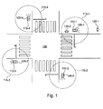
- the figure 1 illustrates an example of implementation of such sound terminals for an intersection 100 of streets.
- the intersection 100 here comprises four traffic lights 105-1 to 105-4, a sound indicating terminal 110-i being associated with each traffic light (the sound terminal 110-1 is associated with the traffic light 105-1, the terminal sound 110-2 is associated with traffic light 105-2, etc.).
- Each 110-i sound terminal is activated by a remote control whose range is predetermined.
- Curves 115-1 to 115-4 illustrate the activation limits of the sound terminals 110-1 to 110-4, respectively.
- the sound signal emitted by the sound terminal 110-1 is a function of the state of the traffic light 105-1.
- the invention solves at least one of the problems discussed above.
- the method according to the invention thus enables the users to associate the audible contents with the sources of the sound indications in order to determine, in particular, a set of directions.
- This method is thus adapted to guiding blind or partially sighted persons.
- said at least two sound guide terminals are activated simultaneously.
- at least one of said sound indications associated with each of said at least two sound guide terminals comprises a first zone of silence.
- the length of said first silence zone is preferably related to the length of at least one sound indication associated with at least one other sound guide terminal.
- the method according to the invention thus allows a simple implementation of guidance by sound indications, easy use of these guide means and allows the use of standard unidirectional sound guide terminals.
- said control signal simultaneously activates said at least two sound guide terminals thus allowing the use of universal remote controls and standard unidirectional sound guide terminals.
- some of the unidirectional sound guide terminals are adapted to transmit and receive activation signals enabling the activation of unidirectional sound guide terminals.
- This embodiment allows programming unidirectional sound guide terminals to execute predetermined sound guide scenarios.
- the method according to the invention thus makes it possible to control a sequence of activation of unidirectional sound guide terminals from one of unidirectional sound guide terminals.
- the method further comprises a step of transmitting at least one second activation signal, said at least one second activation signal being intended for at least one third unidirectional guiding terminal, said at least one second activation signal being adapted to trigger the emission of at least a third sound indication in said at least one third unidirectional guiding terminal, said third sound indication being different from said second sound indication.
- the method is thus capable of activating simultaneously or sequentially several unidirectional sound guide terminals.
- said step of transmitting an activation signal is carried out after a predetermined time following the reception of said first control signal or the emission of an audible indication so that the audible content sound indications are not superimposed.
- At least one of said steps of transmitting a first sound indication and transmitting at least one activation signal can be repeated at least once to at least partially repeat one of the sound indications to facilitate sound guidance.
- said control signal is a radio signal received from a remote control.
- the method according to the invention can thus be implemented using a universal remote control.
- the method further comprises a preliminary step of selecting said first sound instruction making it possible to choose one of several sound instructions, for example as a function of the characteristics of an activation signal, and / or to access a sound instruction stored in a remote system.
- the invention also relates to a computer program comprising instructions adapted to the implementation of each of the steps of the method described above.
- the device according to the invention thus makes it possible to control a sequence of activation of unidirectional sound guide terminals.
- said means adapted to transmit at least one activation signal are adapted to transmit at least a second activation signal, said at least one second activation signal being adapted to activate at least a third device similar sound guide for transmitting a third sound indication, said third sound indication being different from said second sound indication.
- the device is thus able to activate simultaneously or sequentially several unidirectional sound guide terminals.
- the device furthermore comprises wireless transmission means for transmitting at least one of said activation signals in the form of a radio signal and / or receiving means adapted to receive at least the first signal.
- wireless transmission means for transmitting at least one of said activation signals in the form of a radio signal and / or receiving means adapted to receive at least the first signal.
- one of said activation signals in the form of a radio signal in order to simplify the setting up of such a device.
- said means for transmitting an activation signal comprise means for transmitting at least one of said activation signals after a predetermined time following the reception of said control signal or the transmission of a sound indication.
- the device further comprises storage means adapted to store a sequence of sequential instructions for controlling said sound indication transmission means and control signals. Such a sequence of instructions makes it possible to control the activation of one or more unidirectional sound guide terminals.
- the device further comprises means for selecting said first audible indication for selecting one of several audible indications, for example depending on the characteristics of an activation signal, and / or for accessing a sound instruction stored in a remote system.
- the invention also relates to a unidirectional sound guide terminal comprising a recorded sound message, said recorded sound message comprising a first silence zone whose length is at least equivalent to the length of a sound message recorded in another terminal of unidirectional sound guidance allowing the simultaneous activation of several unidirectional sound guide terminals without superposition of the audible contents.
- the methods and devices according to the invention are based on the use of standard sound terminals and remote controls as previously described to assist a person, particularly a blind or visually impaired person, to navigate.
- the actuation of the remote control activates several sound terminals located in the scope range of the remote control.
- the method according to the invention makes it possible to activate two or more sound terminals. At least one message is associated with each sound terminal. These messages correspond to the location of the sound terminals and / or to a direction associated with them to indicate several possible directions to the users. The directions are thus determined by the content of the sound signals emitted and their sources.
- the sound terminals must be sufficiently distant from each other to be able to determine the direction of the sound sources so as to constitute an orientation and sufficiently close to be heard one after the other, in turn, and to be activated simultaneously.
- the positioning of these sound sources, in particular their height and their spacing, is advantageously adjusted in the space according to the place where they are installed (noise level, volume dimensions, acoustic quality, etc.).
- the sound terminals (or the part that emits the sound message) are located at a height of at least 3 meters.
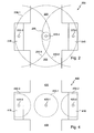
- the figure 2 illustrates an example of implementation of the invention in a public space such as a station.
- the environment 200 in which the invention is installed here is a station hall which comprises in particular an entry 205, a reception desk 210, tickets sales booths 215 and access to the platforms 220.
- Three sound terminals are used here.
- a first sound terminal 225-1 corresponds to the intersection of the reception desk 210 and the counters 215,
- a second sound terminal 225-2 corresponds to the reception office 210 while a third sound terminal 225-3 corresponds to the wickets 215.
- the sound terminals 225-1, 225-2 and 225-3 are here spaced a few meters, typically about four meters.
- the fields of activation of the sound terminals 225-1 to 225-3 by a universal remote control are represented by the curves 230-1 to 230-3, respectively.
- the sound terminals 225-1, 225-2 and 225-3 are activated by the control signal from the remote control and emit an audible signal indicating their position, here "intersection greeting office - wickets", “home office” and “wickets", respectively.
- the sound messages are preferably stored in each of the terminals.
- the sound messages can be stored in a remote server and accessed via a network, wired or not, by the sound terminals. Access to these messages stored on a remote server can be achieved when the sound message is to be disclosed, the initialization of the terminal or periodically.
- a silence zone is inserted at the beginning of at least one sound message.
- the figure 3a illustrates an example of content of the sound messages associated with the sound terminals 225-1, 225-2 and 225-3.
- the sound message 300 associated with the sound terminal 225-1, does not include a silence zone.
- the sound terminal 225-1 is activated at time t, the content of the sound message is directly audible.
- the user hears the message "intersection reception desk - counters" and is able to identify the sound source, here the sound terminal 225-1.
- the sound message 300 has a duration t 1 .
- the sound message 305 associated with the sound terminal 225-2, comprises two parts 305-1 and 305-2.
- the part 305-1 corresponds to a zone of silence while the part 305-2 corresponds to the audible part of the sound message, here "reception desk".
- the duration of the part 305-1 corresponding to a zone of silence is here t 1 + 3s.
- the silence zone 305-1 ends, the audible part 305-2 is sent in turn and the user therefore hears the message "reception desk". He is able to identify the sound source, here the sound terminal 225-2. As illustrated, the sound message 305 has a duration t 2 .
- the sound message 310 associated with the sound terminal 225-3, comprises two parts 310-1 and 310-2.
- the part 310-1 corresponds to a zone of silence while the part 310-2 corresponds to the audible part of the sound message, here "counters".
- the duration of the part 310-1 corresponding to a zone of silence is here t 1 + t 2 + 6s.
- the audible part 310-2 is sent in turn and the user therefore hears the message "counters". He is able to identify the sound source, here the sound terminal 225-3.
- the reference 315 illustrates the message perceived by the user. Each part of this message makes it possible to identify its source and, thus, the user can determine its direction. This sequence can be repeated as many times as necessary, automatically or by operating the remote control.
- the figure 3b illustrates a variant of the figure 3a that direction indications are automatically repeated once to allow the user to fully understand the message and identify sound sources.
- the labels "message 1", “message 2" and “message 3” are replaced by the words “Mes. 1, “Mes. 2 “and” Mes. 3 ", corresponding to the messages” intersection reception desk - counters ",” reception desk “and” counters ", respectively.
- the sound message 300 associated with the sound terminal 225-1, is identical to that of the figure 3a .
- the sound message 305 ' associated with the sound terminal 225-2, comprises four parts 305'-1, 305'-2, 305'-3 and 305'-4.
- the parts 305'-1 and 305'-2 are similar to the parts 305-1 and 305-2, respectively.
- Part 305'-3 corresponds to a zone of silence while part 305'-4 corresponds to in part 305'-2, that is to say, the audible part of the sound message, here "reception desk”.
- the duration of the part 305'-3 corresponding to a zone of silence is here t 3 + 6s, that is to say the length of the sound message associated with the terminal 225-3 (of a duration t 3 ) and two breaks.
- the sound message 310 ' associated with the sound terminal 225-3, comprises four parts 310'-1, 310'-2, 310'-3 and 310'-4.
- Parts 310'-1 and 310'-2 are similar to parts 310-1 and 310-2, respectively.
- the part 310'-3 corresponds to a zone of silence while the part 310'-4 corresponds to the part 310'-2, that is to say to the audible part of the sound message, here "wickets".
- the duration of the part 310'-3 corresponding to a zone of silence is here t 2 + 6s, that is to say the length of the sound message associated with the terminal 225-2 and two pauses.
- the reference 315 illustrates the message perceived by the user, that is to say here the sequence, "intersection reception desk - counters” ... "home office” ... “counters” .. "Reception desk” ... “wickets”.
- this period can be shortened, extended, or deleted.
- Listening to the sound messages and determining the direction of the sound sources associated with these messages allow the user to orientate themselves, for example, towards the reception desk or the ticket windows.
- This sound orientation method is preferably associated with a podotactile tape guidance system.
- This floor marking consisting of a differentiated relief is advantageously used to indicate that sound guidance is available via a universal remote control. So the reference 235 on the figure 2 , corresponds to a podotactile marking indicating to the user that sound guidance is available.
- the sequence of sound messages can be emitted automatically when a presence is detected at a particular point, for example on the podotactile marking 235.
- the detection mechanism sends a control signal to activate the sound terminals.
- the actuation of the remote control activates the sound terminal located in the range field of the remote control by a control signal, this activated terminal activating in turn one or more sound terminals located in the field of this terminal activated by one or more activation signals.
- the sound terminals are modified to receive two different types of signals: a control signal from remote controls and one or more activation signals from sound terminals.
- the modified sound terminals are also able to emit an activation signal of sound terminals.
- the activation signals used for the activation of a sounding terminal by another may in particular be transmitted by a wired link or by a wireless link, such as a radio link.
- the device according to the invention comprises a plurality of sound terminals sufficiently distant from each other to be able to determine the direction of the sound sources so as to constitute an orientation and sufficiently close to be heard one after another, in turn role.
- the positioning of these sound sources, in particular their height and their spacing, is advantageously adjusted in the space according to the place where they are installed (noise level, volume dimensions, acoustic quality, etc.).
- the figure 4 illustrates an example of implementation of the invention in a public space such as a station according to the second embodiment.
- the environment 400 in which the invention is installed is here similar to that of the figure 2 . It also consists of a train station hall that includes a 405 entrance, a 410 welcome desk, 415 ticket counters and access to the 420 platforms. Three sound terminals are used. A first sound terminal 425-1 corresponds to the intersection of the reception office 410 and 415 counters, a second sound terminal 425-2 corresponds to the reception office 410 while a third sound terminal 425-3 corresponds to the wickets 415.
- the activation fields of sound terminals 425-1 to 425-3 by a universal remote control are represented by curves 430-1 to 430-3, respectively.
- the sound terminal 425-1 is activated and emits an audible signal indicating its position, here "intersection home office - counters".
- the 425-2 sound terminal is activated and emits an audible signal indicating its position ("home office")
- the 425-3 sound terminal is activated and emits an audible signal indicating its position ("windows").
- the sound terminal 425-1 After issuing the message "intersection welcome desk - counters", the sound terminal 425-1 emits a first activation signal to activate a neighboring sound terminal, possibly after a predetermined pause time.
- Bollard 425-1 issues an activation signal to activate Bollard 425-2.
- the 425-2 sound terminal then transmits, automatically (that is to say without action on the part of the user), the sound message associated with it, here "home office”.
- the first activated terminal emits a second activation signal to activate another neighboring sound terminal.
- Bollard 425-1 issues an activation signal to activate Bollard 425-3.
- the 425-3 sound terminal then automatically transmits the sound message associated with it, here "wickets”. This sequence can be repeated as many times as necessary.
- listening to these messages and determining the direction of the sound sources associated with these messages allow the user to move for example to the office or to the counters.
- a sequence of instructions can be stored in each sound terminal. If this sequence of instructions is empty, the sound terminal has a standard behavior, that is to say that it emits once the sound message associated with it. If this sequence of instructions is not empty, these instructions are executed one after the other.
- the transmit_message instruction means that the sound message associated with the terminal must be transmitted. According to a preferred embodiment, this instruction is not used because it is not necessary. Indeed, as soon as the sound terminal receives a control signal or an activation signal, it emits the sound message associated with it. The emit_message instruction can be considered as useless.
- the wait (x) statement means that the terminal must wait for the time specified by the x value before executing the next statement.
- the value of x is for example three seconds.
- the transmit_signal (identifier_terminal) instruction means that an activation signal must be sent to activate the audible terminal identified by the terminal_identifier parameter .
- the terminal_identifier parameter is an identifier which makes it possible to identify a sound terminal, preferably a single sound terminal. Depending on the type of connection between the terminal executing this instruction and the terminal identified by identifier_terminal , this identifier is transmitted or not with the control signal. For example, if the control signal is transmitted by a direct wire link established between the terminal executing the instructions and the identified terminal, it is not necessary to transmit the identifier. On the other hand, if the control signal is transmitted by a radio link, it is necessary to transmit the identifier with the command.
- the repeat instruction (i, j) is to repeat the last time i j instructions.
- the values y and z are advantageously determined by the length of the sound messages emitted.
- the attendre_signal_fin instruction is used here to wait for the end of transmission signal of a sound signal of the terminal identified by the borne_identifying parameter.
- the activated terminal must then include the means necessary for the transmission of an end of sound signal emission signal.
- the terminal_identifier parameter makes it possible to check that the end of emission signal has been sent by the activated terminal, this parameter is not essential.
- the sound messages comprise zones of silence at the beginning of the message, as described in the first embodiment, the length of these zones of silence being a function of the length of the messages and the sequencing of the messages, such so that it is not necessary to wait for the end of the disclosure of a message to transmit an activation signal to another sound terminal.
- the communication bus allows communication and interoperability between the different elements included in the computer 500 or connected to it.
- the representation of the bus is not limiting and, in particular, the central unit is capable of communicating instructions to any element of the calculator 500, directly or via another element of the computer 500.
- the executable code of the program (s) enabling the computer 500 to implement the processes according to the invention can be stored, for example, in the hard disk 512 or in the read-only memory 504.
- the memory card 516 can contain data as well as the executable code of the aforementioned programs which, once read by the computer 500, can be stored in the hard disk 512.
- the executable code of the programs can be received via the communication network 520, via the interface 518, to be stored identically to that described above.
- the memory cards can be replaced by any information medium such as, for example, a compact disc (CD-ROM), in general, an information storage medium, readable by a computer or by a microprocessor, integrated or no to the computer, possibly removable, and adapted to store one or more programs whose execution allows the implementation of the method according to the invention.
- CD-ROM compact disc
- CD-ROM compact disc
- program or programs may be loaded into one of the storage means of the computer 500 before being executed.
- the central unit 503 controls the execution of the instructions or portions of software code of the program (s) according to the invention, instructions which are stored in the hard disk 512, in the read-only memory 504 or in the other storage elements. supra.
- the program or programs stored in a non-volatile memory for example the hard disk 512 or the read only memory 504, are transferred into the random access memory 506 (RAM), which then contains the executable code of the one or more program (s) according to the invention, as well as registers for storing the variables and the parameters necessary for the implementation of the invention.
- the computer comprising the device and the programs making it possible to implement the invention can also be a programmed apparatus.
- the instructions of the program (s) implementing The invention may, for example, be implemented in a programmable or specific integrated circuit (Application-Specific Integrated Circuit, ASIC).
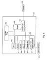
- the figure 6 illustrates an exemplary algorithm for implementing the invention, according to the second embodiment, in a modified sound terminal, that is to say for example a standard sound terminal further comprising storage means for storing a sequence of instructions, means of calculation as presented on the figure 5 for executing an instruction sequence, activation signal receiving means from other modified sound terminals, and activation signal transmitting means for activating other modified sound terminals.
- a modified sound terminal that is to say for example a standard sound terminal further comprising storage means for storing a sequence of instructions, means of calculation as presented on the figure 5 for executing an instruction sequence, activation signal receiving means from other modified sound terminals, and activation signal transmitting means for activating other modified sound terminals.
- a first test is performed to determine if the received signal is a control signal (step 600). If the received signal is not a control signal, a second test is performed to determine whether the received signal is an activation signal (step 605).
- the sound terminal will wait until the next signal is received (return to step 600).
- an audible message is selected (step 610).
- the selection of a sound message is performed, for example, according to a status indicator associated with the sound terminal. This step is not necessary if there is only one sound message associated with the sound terminal.
- the audible message is then transmitted (step 615).
- the sound terminal then goes on hold until the next signal is received (return to step 600).
- step 600 If the received signal is a control signal (step 600), an audible message is selected (step 610) and transmitted (step 615) as previously indicated.
- a test is then performed to determine if the list of instructions associated with the terminal is empty or not (step 620). If the list of instructions is empty, the sound terminal then goes on hold until the next signal is received (return to step 600).
- the instruction list is not empty, the first statement of the list is selected (step 625). The selected instruction is then executed (step 630).
- a test is then performed to determine if the selected instruction is the last of the instruction list or not (step 635). If the selected instruction is the last in the instruction list, the sound terminal will wait until the next signal is received (return to step 600).
- step 640 the next instruction is selected (step 640) and the previous two steps (steps 635 and 640) are repeated.
- the execution of the instructions of the instruction list has the effect of transmitting, if necessary, one or more activation signals to one or more other sound terminals for the transmission of sound messages for multidirectional sound guidance.
- this sound orientation method can advantageously be associated in complex spaces with a tactile land guidance system.
- This floor marking consisting of a differentiated relief is advantageously used to indicate that sound guidance is available via a universal remote control.
- a modified sound terminal can emit a control signal similar to that emitted by a universal remote control, whose range is increased. It is then necessary to judiciously position the sound terminals and to precisely determine the range of the control signals emitted by the sound terminals to control the successive activation of the unmodified terminals.
- sequences of localization messages interspersed with short periods of silence thus create a dynamic orientation that is particularly suitable for people who are blind or visually impaired.
- the same sequence of messages is preferably repeated two or three times before proceeding to the next sequence.
- the user can at any time activate the sound terminal (s) to repeat the sequence of messages.
Landscapes
- Physics & Mathematics (AREA)
- General Physics & Mathematics (AREA)
- Electromagnetism (AREA)
- Mobile Radio Communication Systems (AREA)
Applications Claiming Priority (1)
| Application Number | Priority Date | Filing Date | Title |
|---|---|---|---|
| FR0756255A FR2918493B1 (fr) | 2007-07-03 | 2007-07-03 | Procedes et dispositifs de guidage sonore multidirectionnel |
Publications (1)
| Publication Number | Publication Date |
|---|---|
| EP2015268A1 true EP2015268A1 (de) | 2009-01-14 |
Family
ID=38819395
Family Applications (1)
| Application Number | Title | Priority Date | Filing Date |
|---|---|---|---|
| EP08290649A Withdrawn EP2015268A1 (de) | 2007-07-03 | 2008-07-02 | Verfahren und Vorrichtungen zur multidirektionalen Schallleitung |
Country Status (2)
| Country | Link |
|---|---|
| EP (1) | EP2015268A1 (de) |
| FR (1) | FR2918493B1 (de) |
Cited By (1)
| Publication number | Priority date | Publication date | Assignee | Title |
|---|---|---|---|---|
| FR2971353A1 (fr) * | 2011-02-04 | 2012-08-10 | Phitech | Dispositif de reperage d'une porte d'acces d'un train. |
Citations (7)
| Publication number | Priority date | Publication date | Assignee | Title |
|---|---|---|---|---|
| US4600914A (en) * | 1983-02-10 | 1986-07-15 | Walsh James W | Apparatus for directing attention to specific locations such as emergency exits |
| GB2225661A (en) * | 1988-11-28 | 1990-06-06 | Millbank Electronics Group Lim | Emergency evacuation system |
| US20060071802A1 (en) * | 2004-09-24 | 2006-04-06 | Edwards Systems Technology, Inc. | Fire alarm system with method of building occupant evacuation |
| WO2006094380A1 (en) * | 2005-03-08 | 2006-09-14 | Kleer Semiconductor Corporation | Apparatus and method for wireless audio network management |
| US20060214809A1 (en) * | 2005-03-25 | 2006-09-28 | Honeywell International, Inc. | Directional sound system with messaging |
| EP1788844A2 (de) * | 2005-11-16 | 2007-05-23 | Robert Bosch Gmbh | Beschallungsanlage, Verfahren zur Erzeugung von räumlichen Klangbildern und Software |
| EP1864693A2 (de) * | 2006-06-06 | 2007-12-12 | Honeywell International, Inc. | Verfahren und Systeme zur Steuerung direktionaler Tonerzeuger für ein Routenführungsfeld |
-
2007
- 2007-07-03 FR FR0756255A patent/FR2918493B1/fr not_active Expired - Fee Related
-
2008
- 2008-07-02 EP EP08290649A patent/EP2015268A1/de not_active Withdrawn
Patent Citations (7)
| Publication number | Priority date | Publication date | Assignee | Title |
|---|---|---|---|---|
| US4600914A (en) * | 1983-02-10 | 1986-07-15 | Walsh James W | Apparatus for directing attention to specific locations such as emergency exits |
| GB2225661A (en) * | 1988-11-28 | 1990-06-06 | Millbank Electronics Group Lim | Emergency evacuation system |
| US20060071802A1 (en) * | 2004-09-24 | 2006-04-06 | Edwards Systems Technology, Inc. | Fire alarm system with method of building occupant evacuation |
| WO2006094380A1 (en) * | 2005-03-08 | 2006-09-14 | Kleer Semiconductor Corporation | Apparatus and method for wireless audio network management |
| US20060214809A1 (en) * | 2005-03-25 | 2006-09-28 | Honeywell International, Inc. | Directional sound system with messaging |
| EP1788844A2 (de) * | 2005-11-16 | 2007-05-23 | Robert Bosch Gmbh | Beschallungsanlage, Verfahren zur Erzeugung von räumlichen Klangbildern und Software |
| EP1864693A2 (de) * | 2006-06-06 | 2007-12-12 | Honeywell International, Inc. | Verfahren und Systeme zur Steuerung direktionaler Tonerzeuger für ein Routenführungsfeld |
Cited By (1)
| Publication number | Priority date | Publication date | Assignee | Title |
|---|---|---|---|---|
| FR2971353A1 (fr) * | 2011-02-04 | 2012-08-10 | Phitech | Dispositif de reperage d'une porte d'acces d'un train. |
Also Published As
| Publication number | Publication date |
|---|---|
| FR2918493A1 (fr) | 2009-01-09 |
| FR2918493B1 (fr) | 2011-04-08 |
Similar Documents
| Publication | Publication Date | Title |
|---|---|---|
| EP0306362B1 (de) | System zum Erfassen und Bearbeiten von Daten für die Prüfung von Kraftfahrzeugen | |
| FR2855643A1 (fr) | Procede et appareil a signaux d'etats pour un actionneur de barriere mobile et commande a distance sans fil correspondante | |
| CA2668459A1 (fr) | Systeme de badges lumineux de protection, de securite et de suivi des deplacements | |
| CN105453075A (zh) | 无线触发的智能媒体向导 | |
| EP3196815B1 (de) | Verfahren zur erfassung von passagieren und zur verwaltung und optimierung ihres gemeinsamen transports | |
| EP1212740A1 (de) | Tragbares gerät um reiseverkehrsinformationen anzubieten | |
| FR2848872A1 (fr) | Procede de pilotage d'objets mobiles, notamment des voitures miniatures, mettant en oeuvre un processus de guidage a plusieurs voies et systeme utilisant un tel procede | |
| US20180348004A1 (en) | Light guidance system for processing self-service orders at kiosk stations | |
| EP2015268A1 (de) | Verfahren und Vorrichtungen zur multidirektionalen Schallleitung | |
| EP3922946A1 (de) | Verfahren und vorrichtung zur lenkung einer person in einer verbundenen umgebung | |
| EP3345113A1 (de) | Verfahren zur autorisierung einer aktion durch interaktive und intuitive authentifizierung eines benutzers und zugehörige vorrichtung | |
| FR3163182A3 (fr) | Dispositif de développement de la concentration comprenant trois modes | |
| CN114429361A (zh) | 一种用于抽取资源的方法、设备、介质及程序产品 | |
| CN112014867A (zh) | 一种用户定位方法、装置、服务器及系统 | |
| FR2788858A1 (fr) | Maintien d'un canal avec anticollision dans un systeme d'identification electronique | |
| FR2976704A1 (fr) | Systeme et procede de guidage et de signalisation pour personne deficiente visuelle. | |
| KR20230110352A (ko) | 가상 현실 알림 동기화 | |
| FR2928018A1 (fr) | Systeme permettant d'informer a distance et de maniere selective un utilisateur dans un environnement | |
| EP1481380B1 (de) | Auslöseverfahren und vorrichtung für eine strassenbake | |
| FR2844084A1 (fr) | Telecommande pour capteur ou actionneur electronique | |
| JP2014197301A (ja) | 表示装置、景品提供システム及びプログラム | |
| EP2240919A1 (de) | Verfahren zur kopplung und entkopplung zwischen einem sender und einem empfänger | |
| EP2120000B1 (de) | Verfahren zur Schussunterscheidung während einer Schusssimulation | |
| EP0152713A1 (de) | Sportliche Trainingsgeräte | |
| EP1236167A1 (de) | System zur erfassung von konsumerverhalten, insbesondere auf einem einkaufsmarktgelände |
Legal Events
| Date | Code | Title | Description |
|---|---|---|---|
| PUAI | Public reference made under article 153(3) epc to a published international application that has entered the european phase |
Free format text: ORIGINAL CODE: 0009012 |
|
| AK | Designated contracting states |
Kind code of ref document: A1 Designated state(s): AT BE BG CH CY CZ DE DK EE ES FI FR GB GR HR HU IE IS IT LI LT LU LV MC MT NL NO PL PT RO SE SI SK TR |
|
| AX | Request for extension of the european patent |
Extension state: AL BA MK RS |
|
| 17P | Request for examination filed |
Effective date: 20090324 |
|
| 17Q | First examination report despatched |
Effective date: 20090423 |
|
| AKX | Designation fees paid |
Designated state(s): AT BE BG CH CY CZ DE DK EE ES FI FR GB GR HR HU IE IS IT LI LT LU LV MC MT NL NO PL PT RO SE SI SK TR |
|
| GRAP | Despatch of communication of intention to grant a patent |
Free format text: ORIGINAL CODE: EPIDOSNIGR1 |
|
| RIC1 | Information provided on ipc code assigned before grant |
Ipc: G08B 7/06 20060101ALI20120314BHEP Ipc: G08B 3/10 20060101AFI20120314BHEP |
|
| STAA | Information on the status of an ep patent application or granted ep patent |
Free format text: STATUS: THE APPLICATION IS DEEMED TO BE WITHDRAWN |
|
| 18D | Application deemed to be withdrawn |
Effective date: 20120829 |