EP2015302A1 - Inhaltswiedergabeeinrichtung - Google Patents
Inhaltswiedergabeeinrichtung Download PDFInfo
- Publication number
- EP2015302A1 EP2015302A1 EP07741071A EP07741071A EP2015302A1 EP 2015302 A1 EP2015302 A1 EP 2015302A1 EP 07741071 A EP07741071 A EP 07741071A EP 07741071 A EP07741071 A EP 07741071A EP 2015302 A1 EP2015302 A1 EP 2015302A1
- Authority
- EP
- European Patent Office
- Prior art keywords
- reproduction data
- unit
- contents
- state
- reproducing device
- Prior art date
- Legal status (The legal status is an assumption and is not a legal conclusion. Google has not performed a legal analysis and makes no representation as to the accuracy of the status listed.)
- Withdrawn
Links
Images







Classifications
-
- G—PHYSICS
- G11—INFORMATION STORAGE
- G11B—INFORMATION STORAGE BASED ON RELATIVE MOVEMENT BETWEEN RECORD CARRIER AND TRANSDUCER
- G11B20/00—Signal processing not specific to the method of recording or reproducing; Circuits therefor
- G11B20/10—Digital recording or reproducing
- G11B20/10527—Audio or video recording; Data buffering arrangements
-
- G—PHYSICS
- G11—INFORMATION STORAGE
- G11B—INFORMATION STORAGE BASED ON RELATIVE MOVEMENT BETWEEN RECORD CARRIER AND TRANSDUCER
- G11B7/00—Recording or reproducing by optical means, e.g. recording using a thermal beam of optical radiation by modifying optical properties or the physical structure, reproducing using an optical beam at lower power by sensing optical properties; Record carriers therefor
- G11B7/004—Recording, reproducing or erasing methods; Read, write or erase circuits therefor
- G11B7/005—Reproducing
-
- G—PHYSICS
- G11—INFORMATION STORAGE
- G11B—INFORMATION STORAGE BASED ON RELATIVE MOVEMENT BETWEEN RECORD CARRIER AND TRANSDUCER
- G11B20/00—Signal processing not specific to the method of recording or reproducing; Circuits therefor
- G11B20/10—Digital recording or reproducing
- G11B20/10527—Audio or video recording; Data buffering arrangements
- G11B2020/10537—Audio or video recording
-
- G—PHYSICS
- G11—INFORMATION STORAGE
- G11B—INFORMATION STORAGE BASED ON RELATIVE MOVEMENT BETWEEN RECORD CARRIER AND TRANSDUCER
- G11B20/00—Signal processing not specific to the method of recording or reproducing; Circuits therefor
- G11B20/10—Digital recording or reproducing
- G11B20/10527—Audio or video recording; Data buffering arrangements
- G11B2020/10537—Audio or video recording
- G11B2020/10546—Audio or video recording specifically adapted for audio data
-
- G—PHYSICS
- G11—INFORMATION STORAGE
- G11B—INFORMATION STORAGE BASED ON RELATIVE MOVEMENT BETWEEN RECORD CARRIER AND TRANSDUCER
- G11B20/00—Signal processing not specific to the method of recording or reproducing; Circuits therefor
- G11B20/10—Digital recording or reproducing
- G11B20/10527—Audio or video recording; Data buffering arrangements
- G11B2020/1062—Data buffering arrangements, e.g. recording or playback buffers
- G11B2020/10675—Data buffering arrangements, e.g. recording or playback buffers aspects of buffer control
- G11B2020/10685—Data buffering arrangements, e.g. recording or playback buffers aspects of buffer control input interface, i.e. the way data enter the buffer, e.g. by informing the sender that the buffer is busy
-
- G—PHYSICS
- G11—INFORMATION STORAGE
- G11B—INFORMATION STORAGE BASED ON RELATIVE MOVEMENT BETWEEN RECORD CARRIER AND TRANSDUCER
- G11B20/00—Signal processing not specific to the method of recording or reproducing; Circuits therefor
- G11B20/10—Digital recording or reproducing
- G11B20/10527—Audio or video recording; Data buffering arrangements
- G11B2020/1062—Data buffering arrangements, e.g. recording or playback buffers
- G11B2020/10675—Data buffering arrangements, e.g. recording or playback buffers aspects of buffer control
- G11B2020/10703—Data buffering arrangements, e.g. recording or playback buffers aspects of buffer control processing rate of the buffer, e.g. by accelerating the data output
-
- G—PHYSICS
- G11—INFORMATION STORAGE
- G11B—INFORMATION STORAGE BASED ON RELATIVE MOVEMENT BETWEEN RECORD CARRIER AND TRANSDUCER
- G11B20/00—Signal processing not specific to the method of recording or reproducing; Circuits therefor
- G11B20/10—Digital recording or reproducing
- G11B20/10527—Audio or video recording; Data buffering arrangements
- G11B2020/1062—Data buffering arrangements, e.g. recording or playback buffers
- G11B2020/10675—Data buffering arrangements, e.g. recording or playback buffers aspects of buffer control
- G11B2020/10731—Data buffering arrangements, e.g. recording or playback buffers aspects of buffer control wherein the buffer I/O can be temporarily suspended, e.g. by refusing to accept further data to be buffered
-
- G—PHYSICS
- G11—INFORMATION STORAGE
- G11B—INFORMATION STORAGE BASED ON RELATIVE MOVEMENT BETWEEN RECORD CARRIER AND TRANSDUCER
- G11B20/00—Signal processing not specific to the method of recording or reproducing; Circuits therefor
- G11B20/10—Digital recording or reproducing
- G11B20/10527—Audio or video recording; Data buffering arrangements
- G11B2020/1062—Data buffering arrangements, e.g. recording or playback buffers
- G11B2020/10675—Data buffering arrangements, e.g. recording or playback buffers aspects of buffer control
- G11B2020/1074—Data buffering arrangements, e.g. recording or playback buffers aspects of buffer control involving a specific threshold value
-
- G—PHYSICS
- G11—INFORMATION STORAGE
- G11B—INFORMATION STORAGE BASED ON RELATIVE MOVEMENT BETWEEN RECORD CARRIER AND TRANSDUCER
- G11B20/00—Signal processing not specific to the method of recording or reproducing; Circuits therefor
- G11B20/10—Digital recording or reproducing
- G11B20/10527—Audio or video recording; Data buffering arrangements
- G11B2020/1062—Data buffering arrangements, e.g. recording or playback buffers
- G11B2020/1075—Data buffering arrangements, e.g. recording or playback buffers the usage of the buffer being restricted to a specific kind of data
- G11B2020/10759—Data buffering arrangements, e.g. recording or playback buffers the usage of the buffer being restricted to a specific kind of data content data
-
- G—PHYSICS
- G11—INFORMATION STORAGE
- G11B—INFORMATION STORAGE BASED ON RELATIVE MOVEMENT BETWEEN RECORD CARRIER AND TRANSDUCER
- G11B20/00—Signal processing not specific to the method of recording or reproducing; Circuits therefor
- G11B20/10—Digital recording or reproducing
- G11B2020/10935—Digital recording or reproducing wherein a time constraint must be met
- G11B2020/10944—Real-time recording or reproducing, e.g. for ensuring seamless playback of AV data
Definitions
- the present invention relates to a contents reproducing device for reproducing audio and video contents, and more particularly to a contents reproducing device improved in electric power required to reproduce contents without reducing responsiveness to user request during contents reproduction, and applied to a mobile device.
- a conventionally-known contents reproducing devices is adapted to perform an intermittent reproduction control by storing reproduction data in a storing unit (see, for example, patent document 1).
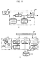
- FIGS. 10(a), 10(b) and 11(a) are block diagrams each showing a conventional contents reproducing device mentioned in the patent document 1.
- FIG. 11(b) refers to FIG. 1 in the patent document 1.
- FIGS. 12(a) and 12(b) are flow charts showing an operation of the conventional contents reproducing device mentioned in the patent document 1. The operations of the conventional contents reproducing device shown in FIGS. 10(a), 10(b) and 11(a) will be described hereinafter.
- FIG. 12(a) is a flow chart showing a contents reproducing operation of an input operation unit 1100 and a system control unit 2200 comprising a system state managing unit 1210 , a system information storing unit 1220 , and a contents reproduction control unit (B) 2230 .
- a user request is inputted from the input operation unit 1100 (in step S1001 ).
- the system state managing unit 1210 reads current state information and system state transition information from the system information storing unit 1220 .
- the system state managing unit 1210 makes the system state be transferred from the current state (referred to as "n-1" ) to the next state (referred to as "n") according to the user request (in step S1002 ).
- the contents reproduction control unit (B) 2230 controls the contents reproducing unit 1300 to perform a process (in step such as fast-forwarding) that is necessary at the next state (in step S1003).
- FIG. 12(b) is a flow chart showing an operation of the contents reproducing unit 1300 including a reproduction data generating unit 1310 , a contents storing unit 1330 and a reproduction data storing unit 1340 , in other words, contents reproduction control unit (B) 2230 controls them.
- the reproduction data generating unit 1310 that received an instruction (a reproduction instruction for example) from the contents reproduction control unit (B) 2230 reads a content out from the contents storing unit 1330 and generates a reproduction data (in step S1102 ).
- the contents reproduction control unit (B) 2230 stores reproduction data generated by the contents storing unit 1330 into the reproduction data storing unit 1340 (in step S1103 ).
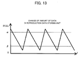
- FIG. 13 is a timing chart showing a change in the amount of reproduction data in the reproduction data storing unit 1340 of the conventional contents reproducing device, mentioned in the patent document 1, and controlled on the basis of the flow chart of FIG. 12 .
- the vertical labels ⁇ and ⁇ on the vertical axis indicate amount data stored in the reproduction data storing unit 1340 when the amount of space available in the reproduction data storing unit 1340 reaches the thresholds ⁇ and ⁇ respectively.
- FIG. 13 is a timing chart showing a change in the amount of reproduction data in the reproduction data storing unit 1340 .
- the determination is made in determination step S1104 of FIG. 12 on whether or not the amount of reproduction data exceeds a vertical label ⁇ .
- the determination is made in determination step Sll05 of FIG. 12 on whether or not the amount of reproduction data does not exceed a vertical label ⁇ .
- the conventional contents reproducing device disclosed in the patent document 1 operates the reproduction generation unit 1310 at a faster pace than the reproduction data processing unit 1320, and stores reproduction data in the reproduction data storing unit 1340 prior to the reproduction by the reproduction data processing unit 1320 . These operations enable the reproduction data generating unit 1310 to become inactive even during the operation of the reproduction data processing unit 1320. Moreover, the conventional contents reproducing device mentioned in the patent document 2 reduces energy consumption during its inactive stage by shutting the power supplied to the reproduction data generating unit 1310.
- Patent document 1 Japanese Patent Laid-Open Publication No. H03-40269
- Patent document 2 Japanese Patent Laid-Open Publication No. H07-161043
- the conventional contents reproducing device however encounters a problem resulting from the fact that the reproduction data is stored in the reproduction data storing unit 1340 in advance.
- the problem in the conventional contents reproducing device is explained according to FIGS. 14(a) and 14(b) .
- the vertical labels ⁇ and ⁇ on the vertical axis indicate the amount of data stored in the reproduction data storing unit 1340 when the available memory space in the reproduction data storing unit 1340 reaches the thresholds ⁇ and ⁇ respectively.
- FIG. 14(a) shows a transition over time of the amount of data stored in the reproduction data storing unit 1340 when a user request occurs at time T1 .
- the conventional contents reproducing device faces the problem of low responsiveness to the user request due to the following reason. Namely, the reproduction data stored in the reproduction data storing unit 1340 up to time T1 is consumed up to time T2 and the system must play the contents that do not correspond to the user request until time T2.
- FIG. 14(b) differs from FIG. 14(a) in that FIG. 14(b) shows a transition over time of the amount of data stored if the content that does not correspond to the user request is first deleted, and subsequently, the content that does correspond to the user request is loaded into the reproduction data storing unit 1340.
- a conventional contents reproducing device has a disadvantage of wasting the power that is required to generate the reproduction data planned to be played from the time T1 to the time T3.
- a contents reproducing device comprises: a reproduction data generating unit operable to generate reproduction data to be reproduced as contents; a reproduction data storing unit in which the reproduction data generated by the reproduction data generating unit is stored; and a reproduction data processing unit operable to read the reproduction data from the reproduction data storing unit in real time, and to reproduce the reproduction data read from the reproduction data storing unit, wherein the contents reproducing device further comprises: a reproduction data generation control unit operable to control the reproduction data generating unit to have the reproduction data generating unit perform an intermittent operation by generating the reproduction data at a rate faster than a rate at which the reproduction data is read from the reproduction data storing unit; an input operation unit to be operated to have the contents reproducing device transit from one state to another state; and a system state determining unit operable to determine whether or not there is a possibility that a reproducing state of the reproduction data processing unit is changed, the reproduction data generation control unit changes a cycle of the intermittent operation, on the basis of the determination made by the system
- the contents reproducing device can reduce an electric power required to reproduce contents without reducing responsiveness to user request.
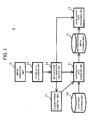
- FIG. 1 is a block diagram showing the contents reproducing device according to the first embodiment of the present invention.
- the contents reproducing device 1 comprises a contents storing unit 10 in which contents data is stored, a reproduction data generating unit 11 operable to generate, from the contents data stored in the contents storing unit 10 , reproduction data to be reproduced as contents, a reproduction data storing unit 12 in which the reproduction data generated by the reproduction data generating unit 11 is stored, a reproduction data processing unit 13 operable to read the reproduction data from the reproduction data storing unit 12 in real time, and to reproduce the reproduction data read from the reproduction data storing unit 12 , a reproduction data generation control unit 14 operable to control the reproduction data generating unit 11 to have the reproduction data generating unit 11 perform an intermittent operation by generating the reproduction data at a rate faster than a rate at which the reproduction data is read from the reproduction data storing unit 12 , an input operation unit 15 to be operated to have the contents reproducing device 1 transit from one state to another state, and a system state determining unit 16 operable to determine whether or not there is a possibility that a reproducing state of the reproduction data processing unit 13
- a term “predictive state” is intended to indicate a state in which there is a possibility that the reproducing state of the reproduction data processing unit 13 is changed when the input operation unit 15 is operated by the user.
- a term “stable state” is intended to indicate a state in which there is no possibility that the reproducing state of the reproduction data processing unit 13 is changed when the input operation unit 15 is operated by the user.
- the contents storing unit 10 is constituted by a memory card, a magnetic disc, an optical disc, or the like having contents data.
- the contents storing unit 10 may be constituted by a buffer operable to buffer the contents data received from a server or the like through a network module (not shown).
- the reproduction data generating unit 11 is constituted by a signal processor such as a digital signal processor (DSP).
- DSP digital signal processor
- the reproduction data generating unit 11 processes the contents data obtained from the contents storing unit 10 , and stores the reproduction data in the reproduction data storing unit 12 .
- the reproduction data generating unit 11 is not limited to a signal processor such DSP.
- the reproduction data generating unit 11 may be constituted by a hardware circuit, or a signal processor together with a hardware circuit.
- the contents data is exemplified by, for example, sounds compressed in a format such as NTEG-1 audio layer 3 (MP3), advanced audio coding (AAC) or windows media audio (WMA), or not compressed data format such as pulse code modulation (PCM).
- MP3 NTEG-1 audio layer 3
- AAC advanced audio coding
- WMA windows media audio
- PCM pulse code modulation
- the reproduction data generating unit 11 When the contents data is exemplified by sounds, the reproduction data generating unit 11 performs signal processing such as decoding of compressed data, and sound quality converting processing such as equalizing or the like.
- the contents data is exemplified by sounds.
- the reproduction data generating unit 11 stores the reproduction data in the reproduction data storing unit 12 in the form of a linear PCM format obtained by applying a signal processing to the contents data.
- the reproduction data storing unit 12 is constituted by a memory device.
- the reproduction data is read from or stored in the memory device on the basis of a first-in first-out (FIFO) method.
- FIFO first-in first-out
- the reproduction data processing unit 13 converts the reproduction data read in real time from the reproduction data storing unit 12 into an analog signal, and outputs it to an audio output device such as a speaker (not shown).
- the reproduction data generation control unit 14 is constituted by a processor such as a central processing unit (CPU) operable to control each unit of the contents reproducing device 1 , and instructs to the reproduction data processing unit 13 to start to generate reproduction data, or to stop generating the reproduction data.
- a processor such as a central processing unit (CPU) operable to control each unit of the contents reproducing device 1 , and instructs to the reproduction data processing unit 13 to start to generate reproduction data, or to stop generating the reproduction data.
- the reproduction data generation control unit 14 controls the reproduction data generating unit 11 to ensure that the reproduction data generating unit 11 performs an intermittent operation to generate the reproduction data at a rate faster than a rate at which the reproduction data is read from the reproduction data storing unit in real time.
- the reproduction data generation control unit 14 has a timer, instructs an amount of reproduction data to be generated by the reproduction data generating unit 11 , and receives a notice of completion of generation of reproduction data from the reproduction data generating unit 11 .
- it measures, using a timer, a period of time during which the reproduction data processing unit 13 reads the reproduction data from the reproduction data storing unit 12 , at a rate the same as a rate at which the contents is reproduced in real time from the reproduction data, without running out of the reproduction data stored in reproduction data storing unit 12 .
- it again instructs an amount of reproduction data to be generated by the reproduction data generating unit 11 . Consequently, the above instructions enables the reproduction data generating unit 11 to perform an intermittent operation by switching back and forth between an active state in which the reproduction data is generated, and an inactive state in which the reproduction data is not generated.
- the reproduction data generation control unit 14 may measure, by using a timer, a start time and an end time necessary to perform the intermittent operation, and issue, at just the right time, an instruction to the reproduction data generating unit 11 to perform the intermittent operation.
- the contents reproducing device 1 may further comprise a reproduction data observing unit (not shown) operable to observe the amount of reproduction data in the reproduction data storing unit 12 .
- the reproduction data generation control unit 14 has the reproduction data generating unit 11 perform the intermittent operation by control the reproduction data generating unit 11 in response to an interrupt signal from the reproduction data observing unit when the amount of reproduction data in the reproduction data storing unit 12 exceeds a predetermined threshold, or falls below a predetermined threshold.
- the input operation unit 15 is constituted by a keyboard device (not shown) and a pointing device (not shown), each of which may be operated to have the contents reproducing device 1 transit from one state to another state.
- the contents reproducing device 1 may be applied to a foldable or a slidable mobile terminal or the like having an open and a closed state.
- the input operation unit 15 may have a sensor operable to detect whether the mobile terminal is in an open or a closed state.
- the system state determining unit 16 and the reproduction data generation control unit 14 are collectively constituted by a processor.
- the system state determining unit 16 determines, for example, that the contents reproducing device 1 is in the predictive state when a display device (not shown) constituted as a user interface displays at least one command. When the command is selected, the state of the reproduction data processing unit 13 is changed in response to the command. Conversely, the contents reproducing device 1 is in the stable state when the display device does not display any selectable commands for changing the state of the reproduction data processing unit 13 .
- a command to change or modify the reproducing state of the reproduction data processing unit 13 may be constituted by a command such as skipping, fast-forwarding, rewinding, sound quality converting, output channel switching, a reproduction request for other reproduction data, or/and the like.
- the input operation unit 15 may be constituted by a sensor operable to detect whether a mobile terminal is in an open state or in a closed state.
- the system state determining unit 16 may determine that the contents reproducing device 1 is in the predictive state when the sensor detects that the mobile terminal is in the open state.
- the system state determining unit 16 may determine that the contents reproducing device 1 is in the stable state when the sensor detects that the mobile terminal is in the closed state.
- the reproduction data generation control unit 14 changes a cycle at which the reproduction data processing unit 13 performs the intermittent operation, on the basis of the determination made by the system state determining unit 16 , when the reproduction data processing unit 13 is reproducing the contents from the reproduction data.
- the reproduction data generation control unit 14 controls the reproduction data generating unit 11 to shorten the cycle of the intermittent operation when the contents reproducing device 1 is in the predictive state, to ensure that the cycle of the intermittent operation in the predictive state is smaller than that of the intermittent operation in the stable state.
- the reproduction data generation control unit 14 controls the reproduction data generating unit 11 to ensure that the amount of reproduction data to be generated by the reproduction data generating unit in the predictive state is smaller than the amount of reproduction data to be generated by the reproduction data generating unit in the stable state.
- the sampling frequency of the reproduction data generated by the reproduction data generating unit 11 may be 48 kHz.
- the reproduction data generation control unit 14 controls the reproduction data generating unit 11 to have the reproduction data generating unit 11 generate reproduction data equal to 48 frames in the predictive state, and to have the reproduction data generating unit 11 generate reproduction data equal to 24 frames in the stable state.
- the cycle of the intermittent operation to be performed by the reproduction data generating unit 11 is 1 [cycle/second] when the contents reproducing device 1 is in the predictive state.
- the cycle of the intermittent operation to be performed by the reproduction data generating unit 11 is 0.5 [cycle/second] when the contents reproducing device 1 is in the stable state.
- a period of time over which the reproduction data generating unit 11 generates the reproduction data when the contents reproducing device 1 is in the predictive state is set shorter than that when it is in the stable state.
- the reproduction data generation control unit 14 prevent the cycle of the intermittent operation of the reproduction data generating unit 11 from being changed too frequently by the following step. Namely, when the contents reproducing device 1 changes from the predictive state to the stable state by the input operation with the input operation unit 15 , the reproduction data generation control unit 14 controls the reproduction data generating unit 11 so that its intermittent operation is lengthened only after a certain amount of time, during which the contents reproducing device 1 is in the stable state, has passed.
- the clock/power source control unit 17 reduces power consumption of the contents reproducing device 1 by limiting either or both a clock signal and an electric power, which are provided to the reproduction data generating unit 11 . Further, the clock/power source control unit 17 removes the above limited operation when it receives a control signal from the reproduction data generation control unit 14 which occurs before instructing the amount of the reproduction data that the reproduction data generating unit 11 generates.
- the clock/power source control unit 17 is adapted to shut off the clock signal, to reduce the frequency of the clock signal, or to reduce the voltage of the clock signal by controlling a clock signal generating circuit (not shown) generating the clock signal to be supplied to the reproduction data generating unit 11 .
- the clock/power source control unit 17 is adapted to shut off the power circuit, or to reduce the output voltage by controlling a power circuit (not shown) supplying the electric power to the clock/power source control unit 17 .
- the clock/power source control unit 17 may limit a clock signal and/or an electric power, which are provided to the reproduction data generation control unit 14 excluding a timer.
- the contents reproducing device 1 may have reproduction data observing unit operable to generate an output signal to be outputted to the clock/power source control unit 17 when the reproduction data generating unit 11 is in an inactive state.
- the clock/power source control unit 17 may limit a clock signal and/or an electric power, which are provided to the reproduction data generation control unit 14 excluding a section for receiving an interrupt signal from the reproduction data observing unit.
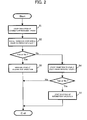
- FIG. 2 is a flow chart showing the operation to be performed by the contents reproducing device 1 when the input operation unit 15 is operated under the condition that the reproduction data processing unit 13 is reproducing the reproduction data, and the reproduction data generating unit 11 is performing the intermittent operation.
- step S1 When the user operates the input operation unit 15 , the state of the contents reproducing device 1 is changed (in step S1 ).
- the system state determining unit 16 determines whether or not the state of the contents reproducing device 1 is changed from the stable state to the predictive state (in step S2 ).
- the reproduction data generation control unit 14 controls the reproduction data generating unit 11 to shorten the cycle of the intermittent operation (in step S3 ).
- the system state determining unit 16 determines whether or not the state of the contents reproducing device 1 has changed from the predictive state to the stable state (in step S4 ).
- the reproduction data generation control unit 14 controls the reproduction data generating unit 11 to lengthen the cycle of the intermittent operation (in step S5 ).
- FIG. 3(a) is a timing chart showing the change of the amount of reproduction data in the reproduction data storing unit 12 under the condition that the cycle of the intermittent operation is not changed.
- FIG. 3(b) is a timing chart showing the change of the amount of reproduction data in the reproduction data storing unit 12 under the condition that the cycle of the intermittent operation is changed.
- the state of the contents reproducing device 1 is changed from the stable state to the predictive state at time t1 .
- the input operation unit 15 is operated to change the state of the reproduction data processing unit 13 at time t2 .
- the contents reproducing device can reduce an electric power required to reproduce contents without reducing responsiveness to user request by taking the following steps. Namely, the cycle of the intermittent operation of the reproduction data generating unit 11 is shortened when the contents reproducing device 1 is in the predictive state. Consequently, the contents reproducing device 1 of the first embodiment can shorten, on an average, the time required to output the reproduction data affected by the change of the reproducing state of the reproduction data processing unit 13 .
- FIG. 4 is a block diagram showing the construction of the contents reproducing device according to the second embodiment of the present invention. As shown in FIG. 4 , the same reference numerals are used for those elements that are also contained in FIGS. 10 and 11 . Furthermore, in this embodiment, an input operation unit 1100 , a system control unit 1205 and a contents reproduction control unit 1230 exemplary illustrate, respectively, the operation unit, the system state determining unit, and the reproduction data generation control unit of the invention.
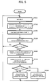
- FIGS. 5 and 6 are flow charts showing a content reproducing processing to be performed by the contents reproducing device according to the second embodiment. The operation of the contents reproducing device shown in FIG. 4 will be explained hereinafter with reference to the flow charts of FIGS. 5 and 6 .
- FIG 5 is a flow chart showing the operation of the input operation unit 1100 and a system control unit 1200 having a function to predict a user operation.
- the system control unit 1200 comprises a system state managing unit 1210 , a system information storing unit 1220 , a contents reproduction control unit (A) 1230 , a state after next candidate extracting unit 1240 , and a contents reproduction control determining unit 1250 .
- the steps S1001 and S1003 are the same as those of the flow chart shown in FIG. 12 , and will not described hereinafter.
- the state after next candidate extracting unit 1240 reads a system state transition information from the system information storing unit 1220 , then extracts candidates of the state after next (defmed as "n+1" ) from the information of the next state "n” and the system state transition information (in step S1005 ).
- the contents reproduction control determining unit 1250 determines whether or not a control related to the content reproduction is in candidates of the state after next (in step S1006 ), and notifies the contents reproduction control unit 1230 (A) to shorten the cycle of the intermittent operation if a control related to content reproduction exists (in step S1007 ).
- the contents reproduction control determining unit 1250 notify the contents reproduction control unit (A) 1230 to lengthen the cycle of the intermittent operation compared to that the unit 1250 notified in S1007 (in step S1008 ).
- FIG. 6 is a control flow chart showing an operation of the contents reproducing unit 1300 including the reproduction data generating unit 1310 , the contents storing unit 1330 , and the reproduction data storing unit 1340 .
- FIG. 6 is a flow chart showing the processing of the contents reproduction control unit (A) 1230 .
- the steps S1102 and S1105 of this flow chart are the same as those of the flow chart shown in FIG. 12(b) , will not described hereinafter.
- the contents reproduction control unit (A) 1230 resets the available memory threshold ⁇ of the reproduction data storing unit 1340 , which is used in the step S1104 , to ⁇ 1 or ⁇ 2 according to the cycle of the intermittent operation designated assigned by the contents reproduction control determining unit 1250 (in step S1101 ).
- the reproduction data processing unit 1320 reproduces the reproduction data continuously by constantly reading reproduction data from the reproduction data storing unit 1340 .
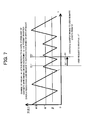
- FIGS. 7(a) and 7(b) A method of improving the problems raised in FIGS. 14(a) and 14(b) is described hereinafter with reference to FIGS. 7 and 8 .
- the labels ⁇ 1 , ⁇ 2 and ⁇ on the vertical axis indicate the amount of reproduction data in the reproduction data storing unit 1340 when the available memory space in the reproduction data storing unit 1340 reaches the respective thresholds ⁇ 1 , ⁇ 2 and ⁇ .
- FIG. 7 is a timing chart for explaining the transition over time of the amount of data stored in the reproduction data storing unit 1340 when a user request occurs at time T1' .
- the contents reproducing device of this embodiment plays a content that do not correspond to the user request between time T1' and time T2' due to the fact that the reproduction data that have been stored up to the time T1' in the reproduction data storing unit 1340 is consumed until T2' . Therefore, the contents reproducing device cannot respond to the user request until T2' .
- the detection threshold ⁇ for the memory available in the reproduction data storing unit 1340 is set to ⁇ 1 (in step so that ⁇ 1 > ⁇ 2 holds)
- the maximum memory storage of the reproduction data storing unit 1340 is reduced compared to the case in which the detection threshold ⁇ is set to ⁇ 2 . Therefore, this reduction of the maximum memory storage enables the contents reproducing device of this embodiment to improve, on the average, the user responsiveness relative to the conventional contents reproducing device.
- FIG. 8(b) differs from FIG. 7(a) in that FIG. 8(b) is a timing chart for explaining the transition over time of the amount of data stored in case when the content that does not correspond to the user request is first deleted. Then, the content that does correspond to the user request is stored in the reproduction data storing unit 1340 . In this case, the reproduction data which was previously planned to be played from the time T1' until the time T3' is deleted. Therefore, the power used to generate the data during this time interval (in step S' in FIG. 8 ) is wasted.
- the detection threshold ⁇ for the memory available in the reproduction data storing unit 1340 is set to ⁇ 1 (in step so that ⁇ 1 > ⁇ 2 holds)
- the maximum amount of the reproduction data that is to be deleted is reduced compared to the case in which the detection threshold ⁇ is set to ⁇ 2 . Therefore, this reduction of the maximum memory storage enables the contents reproducing device of this embodiment to reduce the average energy consumption relative to the conventional contents reproducing device.
- FIG. 9(a) is a hierarchy diagram showing a hierarchical menu of the contents reproducing device.
- FIG. 9(b) is a diagram for explaining an operation necessary to extract candidate information on the state after next "n+1" .
- Each of "3-1-1) play", “3-1-2) fast forward”, “3-1-3) rewind", and "3-1-4) equalizer" of the hierarchical menu shown in FIG. 9(a) contains a processing necessary to have the contents reproduction control unit 1230 control the contents reproducing unit 1300 , while the hierarchical menu excluding the items listed above does not contain a processing necessary to have the contents reproduction control unit 1230 control the contents reproducing unit 1300 .
- a process A determines the next state “n” on the basis of the current state “n-1” and the user input information obtained by the input operation unit 1100 .
- a process B extracts candidate information for the state after next “n+1” from the next state “n” and the system state transition information read from the system information storing unit 1220 .
- the candidate information for the state after next “n+1” includes: "3-1-1) play", “3-1-2) fast forward", “3-1-3) rewind", and "3-1-4) equalizer", while "3-1-5) stop play” is excluded from this list.
- the contents reproduction control determining unit 1250 determines that "3-1) play” has candidate information for the state after next "n+1” having a control processing for having the contents reproduction control unit 1230 control the contents reproducing unit 1300 , determines that there is a possibility that "3-1-1) play", “3-1-2) fast forward", “3-1-3) rewind", and "3-1-4) equalizer” are selected, and shortens the cycle of the intermittent operation of the contents reproducing unit 1300 .
- the contents reproduction control determining unit 1250 determines that the next state “n” does not have candidate information for the state after next "n+1" having a control processing for having the contents reproduction control unit 1230 control the contents reproducing unit 1300 , and lengthens the cycle of the intermittent operation of the contents reproducing unit 1300 .
- the cycle of the intermittent operation may be controlled by using a timer as a part of the control by the contents reproduction control unit (A) 1230 .
- the open-closed state information of the mobile terminal may also be used as the user input information to be taken by the input operation unit 1100 .
- the contents reproducing device is especially applicable to the audio player devices powered by a battery, or mobile phones having a function to reproduce audio and video contents.
Landscapes
- Engineering & Computer Science (AREA)
- Multimedia (AREA)
- Signal Processing (AREA)
- Signal Processing For Digital Recording And Reproducing (AREA)
- Television Signal Processing For Recording (AREA)
Applications Claiming Priority (2)
| Application Number | Priority Date | Filing Date | Title |
|---|---|---|---|
| JP2006125505 | 2006-04-28 | ||
| PCT/JP2007/057635 WO2007125737A1 (ja) | 2006-04-28 | 2007-04-05 | コンテンツ再生装置 |
Publications (2)
| Publication Number | Publication Date |
|---|---|
| EP2015302A1 true EP2015302A1 (de) | 2009-01-14 |
| EP2015302A4 EP2015302A4 (de) | 2012-05-30 |
Family
ID=38655272
Family Applications (1)
| Application Number | Title | Priority Date | Filing Date |
|---|---|---|---|
| EP20070741071 Withdrawn EP2015302A4 (de) | 2006-04-28 | 2007-04-05 | Inhaltswiedergabeeinrichtung |
Country Status (5)
| Country | Link |
|---|---|
| US (1) | US8463106B2 (de) |
| EP (1) | EP2015302A4 (de) |
| JP (1) | JP4948531B2 (de) |
| CN (2) | CN101454834B (de) |
| WO (1) | WO2007125737A1 (de) |
Families Citing this family (3)
| Publication number | Priority date | Publication date | Assignee | Title |
|---|---|---|---|---|
| JP5857591B2 (ja) * | 2011-09-29 | 2016-02-10 | 三菱電機株式会社 | 映像配信装置 |
| JP6051729B2 (ja) * | 2012-09-24 | 2016-12-27 | オンキヨー株式会社 | 低消費電力装置 |
| US9065882B2 (en) | 2013-03-05 | 2015-06-23 | Comcast Cable Communications, Llc | Processing signaling changes |
Family Cites Families (22)
| Publication number | Priority date | Publication date | Assignee | Title |
|---|---|---|---|---|
| JPH07105117B2 (ja) | 1989-07-06 | 1995-11-13 | アルパイン株式会社 | ディスクプレーヤの演奏方法 |
| CN1075024A (zh) * | 1992-01-29 | 1993-08-04 | 松下电器产业株式会社 | 录放装置 |
| US5787225A (en) * | 1993-03-29 | 1998-07-28 | Matsushita Electric Industrial Co., Ltd. | Optical disk apparatus for the reproduction of compressed data |
| JP3157342B2 (ja) * | 1993-04-15 | 2001-04-16 | 三洋電機株式会社 | デジタル信号記録媒体再生装置 |
| JP3104110B2 (ja) | 1993-04-26 | 2000-10-30 | ソニー株式会社 | 再生装置 |
| JPH07141777A (ja) | 1993-11-17 | 1995-06-02 | Pioneer Electron Corp | 記録媒体再生装置 |
| JPH07161043A (ja) | 1993-12-02 | 1995-06-23 | Matsushita Electric Ind Co Ltd | 光ディスク装置 |
| US5671204A (en) * | 1994-05-25 | 1997-09-23 | Victor Company Of Japan, Ltd. | Variable transfer rate data reproduction apparatus |
| JP3486988B2 (ja) | 1994-10-19 | 2004-01-13 | ソニー株式会社 | 再生装置 |
| JPH08137754A (ja) | 1994-11-10 | 1996-05-31 | Fuji Xerox Co Ltd | ディスクキャッシュ装置 |
| CN1312609C (zh) * | 1995-04-08 | 2007-04-25 | 索尼公司 | 编辑系统 |
| JP4000425B2 (ja) | 1996-11-20 | 2007-10-31 | ソニー株式会社 | データ再生装置およびデータ再生方法 |
| JP3807593B2 (ja) * | 2000-07-24 | 2006-08-09 | 株式会社ルネサステクノロジ | クロック生成回路および制御方法並びに半導体記憶装置 |
| JP2002124019A (ja) | 2000-10-17 | 2002-04-26 | Nec Corp | ディスク装置用のシーケンシャルデータ送出用適応バッファの制御装置とその制御方法 |
| JP2003272302A (ja) * | 2002-03-19 | 2003-09-26 | Toshiba Corp | 情報再生装置及び情報再生方法 |
| US6890078B2 (en) * | 2002-07-03 | 2005-05-10 | Canon Kabushiki Kaisha | Projection type image display apparatus and image display system |
| CN101369441A (zh) | 2002-08-08 | 2009-02-18 | 松下电器产业株式会社 | 盘形信息记录介质及记录或再现方法、信息记录设备及信息再现设备 |
| EP2819123A1 (de) * | 2003-01-02 | 2014-12-31 | Samsung Electronics Co., Ltd | Multimediavorrichtung mit Audioausgabe mit Slideshow-Begleitung |
| JP2005289640A (ja) | 2004-04-05 | 2005-10-20 | Akira Shimizu | 無停止型バットスプライス装置 |
| JP4442294B2 (ja) * | 2004-04-09 | 2010-03-31 | ソニー株式会社 | コンテンツ再生装置,プログラム,コンテンツ再生制御方法 |
| JP4959935B2 (ja) | 2004-11-09 | 2012-06-27 | 株式会社東芝 | 復号装置 |
| JP2007101772A (ja) * | 2005-10-03 | 2007-04-19 | D & M Holdings Inc | 再生装置及び再生方法 |
-
2007
- 2007-04-05 EP EP20070741071 patent/EP2015302A4/de not_active Withdrawn
- 2007-04-05 WO PCT/JP2007/057635 patent/WO2007125737A1/ja not_active Ceased
- 2007-04-05 JP JP2008513125A patent/JP4948531B2/ja not_active Expired - Fee Related
- 2007-04-05 CN CN2007800193905A patent/CN101454834B/zh not_active Expired - Fee Related
- 2007-04-05 CN CN201110403890.7A patent/CN102436833B/zh not_active Expired - Fee Related
- 2007-04-05 US US12/298,637 patent/US8463106B2/en not_active Expired - Fee Related
Also Published As
| Publication number | Publication date |
|---|---|
| CN101454834A (zh) | 2009-06-10 |
| JPWO2007125737A1 (ja) | 2009-09-10 |
| CN102436833B (zh) | 2016-01-20 |
| JP4948531B2 (ja) | 2012-06-06 |
| WO2007125737A1 (ja) | 2007-11-08 |
| EP2015302A4 (de) | 2012-05-30 |
| US20090220217A1 (en) | 2009-09-03 |
| CN102436833A (zh) | 2012-05-02 |
| CN101454834B (zh) | 2012-02-08 |
| US8463106B2 (en) | 2013-06-11 |
Similar Documents
| Publication | Publication Date | Title |
|---|---|---|
| JP2001052437A (ja) | ディスク記録装置 | |
| KR100705000B1 (ko) | 기록/재생장치 및 기록/재생방법 | |
| CN1882998B (zh) | 用于重放来自存储媒介的媒体流的重放设备和方法 | |
| JP2000339864A (ja) | ディスク再生装置 | |
| US8463106B2 (en) | Contents reproducing device | |
| KR20110030550A (ko) | 태스크 로드를 측정하기 위한 방법 및 시스템 | |
| KR101036232B1 (ko) | 오디오 재생을 위한 데이터 처리 방법, 오디오 재생 방법 및 오디오 재생 장치 | |
| KR100639110B1 (ko) | 프레임 단위로 이루어진 오디오 스트림 데이터의 시간정보산출방법 | |
| US7941032B2 (en) | Information processing device and program | |
| US8891945B2 (en) | Recording/reproducing method and recording/reproducing device | |
| JPH11149706A (ja) | 記録再生装置及び記録再生方法 | |
| JP2008269745A (ja) | 再生装置、プログラム、及び再生方法 | |
| US20060126449A1 (en) | Information processing device and program | |
| KR100721292B1 (ko) | 휴대용 멀티미디어의 하드디스크 액세스 장치 및 그 방법 | |
| JP3949808B2 (ja) | 情報記録装置及び情報記録方法 | |
| CN100369473C (zh) | 记录装置和方法 | |
| JP2623045B2 (ja) | ディスク再生装置の再生制御回路 | |
| JP4610302B2 (ja) | 記録再生装置 | |
| KR20110013666A (ko) | 멀티미디어 데이터 재생 장치 및 방법 | |
| JP2003272302A (ja) | 情報再生装置及び情報再生方法 | |
| KR100816559B1 (ko) | 빠른 재생 복귀 속도를 갖는 cd 데이터 재생 방법 | |
| JPH06103699A (ja) | 情報再生装置 | |
| JP4882891B2 (ja) | 記録装置、記録方法 | |
| JP2008084382A (ja) | 圧縮データ再生方法 | |
| JP2007101772A (ja) | 再生装置及び再生方法 |
Legal Events
| Date | Code | Title | Description |
|---|---|---|---|
| PUAI | Public reference made under article 153(3) epc to a published international application that has entered the european phase |
Free format text: ORIGINAL CODE: 0009012 |
|
| 17P | Request for examination filed |
Effective date: 20081030 |
|
| AK | Designated contracting states |
Kind code of ref document: A1 Designated state(s): AT BE BG CH CY CZ DE DK EE ES FI FR GB GR HU IE IS IT LI LT LU LV MC MT NL PL PT RO SE SI SK TR |
|
| AX | Request for extension of the european patent |
Extension state: AL BA HR MK RS |
|
| DAX | Request for extension of the european patent (deleted) | ||
| RBV | Designated contracting states (corrected) |
Designated state(s): DE FR GB |
|
| A4 | Supplementary search report drawn up and despatched |
Effective date: 20120504 |
|
| RIC1 | Information provided on ipc code assigned before grant |
Ipc: G06F 3/06 20060101ALI20120426BHEP Ipc: G06F 12/08 20060101ALI20120426BHEP Ipc: G11B 20/10 20060101AFI20120426BHEP Ipc: G11B 7/005 20060101ALI20120426BHEP Ipc: G11B 19/00 20060101ALI20120426BHEP Ipc: G11B 27/10 20060101ALI20120426BHEP |
|
| 17Q | First examination report despatched |
Effective date: 20130923 |
|
| RAP1 | Party data changed (applicant data changed or rights of an application transferred) |
Owner name: PANASONIC INTELLECTUAL PROPERTY MANAGEMENT CO., LT |
|
| STAA | Information on the status of an ep patent application or granted ep patent |
Free format text: STATUS: THE APPLICATION HAS BEEN WITHDRAWN |
|
| 18W | Application withdrawn |
Effective date: 20151014 |