EP2015332A2 - Close-loop relay driver with equal-phase interval - Google Patents
Close-loop relay driver with equal-phase interval Download PDFInfo
- Publication number
- EP2015332A2 EP2015332A2 EP08012078A EP08012078A EP2015332A2 EP 2015332 A2 EP2015332 A2 EP 2015332A2 EP 08012078 A EP08012078 A EP 08012078A EP 08012078 A EP08012078 A EP 08012078A EP 2015332 A2 EP2015332 A2 EP 2015332A2
- Authority
- EP
- European Patent Office
- Prior art keywords
- equal
- relay
- relays
- current flow
- phase
- Prior art date
- Legal status (The legal status is an assumption and is not a legal conclusion. Google has not performed a legal analysis and makes no representation as to the accuracy of the status listed.)
- Withdrawn
Links
- 238000000034 method Methods 0.000 claims description 11
- 230000001276 controlling effect Effects 0.000 claims description 4
- 230000001105 regulatory effect Effects 0.000 claims description 3
- 230000000630 rising effect Effects 0.000 claims description 3
- 238000007599 discharging Methods 0.000 claims 1
- 230000000977 initiatory effect Effects 0.000 claims 1
- 238000012544 monitoring process Methods 0.000 claims 1
- 238000010586 diagram Methods 0.000 description 8
- 230000033228 biological regulation Effects 0.000 description 2
- 239000003990 capacitor Substances 0.000 description 2
- 230000006870 function Effects 0.000 description 2
- 230000017525 heat dissipation Effects 0.000 description 1
- 239000000463 material Substances 0.000 description 1
- 238000012986 modification Methods 0.000 description 1
- 230000004048 modification Effects 0.000 description 1
Images




Classifications
-
- H—ELECTRICITY
- H01—ELECTRIC ELEMENTS
- H01H—ELECTRIC SWITCHES; RELAYS; SELECTORS; EMERGENCY PROTECTIVE DEVICES
- H01H47/00—Circuit arrangements not adapted to a particular application of the relay and designed to obtain desired operating characteristics or to provide energising current
- H01H47/22—Circuit arrangements not adapted to a particular application of the relay and designed to obtain desired operating characteristics or to provide energising current for supplying energising current for relay coil
- H01H47/32—Energising current supplied by semiconductor device
- H01H47/325—Energising current supplied by semiconductor device by switching regulator
Definitions
- the present disclosure relates to methods and systems for controlling current to mechanical relays.
- Coils in mechanical relays generate heat.
- the relay needs large current to pull in the armature. Once the armature is pulled in, only a small current is needed to hold the armature in place.
- Pulse width modulated (PWM) relay driver systems can reduce coil power consumption and associated heat dissipation significantly.
- the power supply current driving current
- the power supply current is discontinuous.
- driving current driving current
- the sum of the discontinuous current results in large discontinuous current.
- filters can be implemented to smooth the driving current.
- two stages of band-pass filters, each including an inductor and a capacitor, are needed. Since inductors are expensive, two stages of band-pass filters increase the system cost.
- the present teachings generally include a power distribution system.
- the power distribution system generally includes at least two relays.
- An equal-phase pulse generator generates pulse signals in equal phase intervals.
- FIG. 1 is a block diagram illustrating a vehicle including a power distribution system in accordance with various aspects of the present teachings.
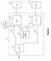
- FIG. 2 is a block diagram illustrating a relay driver system of the power distribution system in accordance with various aspects of the present teachings.
- Figure 3 is a graph illustrating exemplary current values and an exemplary total current value generated by the relay driver system in accordance with various aspects of the present teachings.
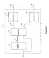
- Figure 4 is a block diagram illustrating an equal-phase pulse generator of the relay driver system in accordance with various aspects of the present teachings.
- Figure 5 is an electrical schematic diagram illustrating an exemplary equal-phase pulse generator of the relay driver system in accordance with various aspects of the present teachings.
- FIG. 6 is a block diagram illustrating an exemplary driver of the relay driver system in accordance with various aspects of the present teachings.
- Figure 7 is an electrical schematic diagram illustrating an exemplary driver of the relay driver system in accordance with various aspects of the present teachings.
- the term, component and/or device can refer to one or more of the following: an application specific integrated circuit (ASIC), an electronic circuit, a processor (shared, dedicated or group) and memory that executes one or more software or firmware programs, a combinational logic circuit and/or other suitable mechanical, electrical or electro-mechanical components that can provide the described functionality and/or combinations thereof.
- ASIC application specific integrated circuit
- processor shared, dedicated or group
- memory that executes one or more software or firmware programs
- Figure 1 illustrates a vehicle generally at 10 that can include a power distribution system 12.
- the power distribution system 12 can provide electrical energy from a vehicle battery 14 to various electrical systems 16 of the vehicle 10.
- the power distribution system 12 can include one or more instances of a relay driver system 18 that can control the flow of current to operate at least relays 20a and 20b.
- the relay driver system 18 can control the total supply of current to the relays 20a and 20b.
- the relay driver system 18 can control the flow of current to operate at least two relays 20a and 20b.
- the relay driver systems and methods of the present disclosure can control the flow of current to operate multiple relays.
- Figure 2 illustrates a relay driver system that can control the flow of current to operate eight relays 20a-20h.
- the remainder of the disclosure will be discussed in the context of the relay driver system 18 that can control eight relays 20a-20h.
- the relay driver system 18 can include one or more components such as an interface 22, an equal-phase pulse generator 24, drivers 26a-26h, one for each of the relays 20a-20h, and/or combinations thereof.
- the interface 22 can communicate with other systems of the vehicle 10 ( Figure 1 ).
- the interface 22 can receive and can process input signals (generally referred to as 28) that request operation of the relays 20a-20h.
- the interface 22 can direct the input signal 28a-28h to the appropriate the drivers 26a-26h.
- the equal-phase pulse generator 24 can generate a pulse signal 30a-30h to each of the drivers 26a-26h. According to various aspects of the present teachings, the equal-phase pulse generator 24 can generate the pulse signals 30a-30h in equal phase intervals.
- a pulse signal 30a-30h can be generated every forty-five degrees.
- the phase interval of the pulse signals 30a-30h can vary depending on the number of drivers 26a-26h and thus, the number of relays 20a-20h.
- the drivers 26a-26h can receive the corresponding pulse signals 30a-30h and the related input signals 28a-28h. Based on the pulse signals 30a-30h and the input signals 28a-28h, the drivers 26a-26h can regulate the flow of current from the vehicle battery 14 to the relays 20a-20h. According to various aspects of the present teachings, the drivers 26a-26h can regulate the flow of current such that the current to each relay can be discontinuous. However, the supply of current to each relay can lag the previous relay by the phase interval, for example forty-five degrees, thus, the total supply of current supplied by the relay driver system 18 can be distributed as shown in Figure 3 . Furthermore, the total supply of current supplied at any one time can be significantly reduced.
- the equal-phase pulse generator 24 can generate pulse signals 30a-30h according to equal phase intervals.
- the equal-phase pulse generator 24 can include components such as a frequency divider 32, a shift register 34, two or more edge extractors 36a-36h, one for each of the drivers 26a-26h ( Figure 2 ), and/or combinations thereof.
- the frequency divider 32 can generate an output signal 38 in equal phase intervals.
- the frequency divider 32 can be implemented as a general purpose counter configured to operate as a frequency divider.
- the phase interval can be determined based on a division ratio.
- the output signal 38 of the frequency divider 32 can be received by the shift register 34. Based on the output signal 38, the shift register 34 can generate drive signals to each of the edge extractors 36a-36h. Drive signals 40a-40b generated by the shift register 34 are of equal phase intervals. The edge extractors 36a-36h can then generate the pulse signals 30a-30h by extracting a rising edge of the drive signals 40a-40b generated by the shift register 34.
- an electrical schematic diagram illustrates an example of the equal-phase pulse generator 24 including eight channels shown in Figure 4 .
- the frequency divider 32 can include a counter U2 and an inverter U5A. For every eight clocks, there can be one output signal at Carry terminal. The Carry signal can be fed back to the Load input through U3C to reset the counter for another eight clock counting. The Carry signal can also be sent to the input of shift register 34 (DS1). This signal can then be shifted out from Q0 to Q7 clock by clock. As a result, signals on Q0 to Q7 can be of equal time interval or equal phase interval.
- the time interval can be the clock period.
- Each edge extractor 36a-36h can include a resistor R1, an inverter U3A, and a logic gate U1A. Each edge extractor 36a-36h can receive signals from Q0 to Q7. On the rising edge, an edge extractor 36a-36h can output a short pulse for triggering purposes of a main switch 54 (shown in Figure 6 ).
- the drivers 26a-26h can control the flow of current to the relays 20a-20h based on the pulse signals 30a-30h.
- the drivers 26a-26h can control the current flow to provide a full battery voltage to the relays 20a-20h during an initial pull-in period (i.e., moving an armature of the relay).
- the current flow can be regulated such that a position of the armature of the relays 20a-20h can be maintained without utilizing excess electrical energy and/or creating excess heat.
- the driver 26a shown in the example of Figure 6 can generally include a pull-in pulse circuit 42, a freewheeling circuit 44, a fast turn-off circuit 46, a sense resistor 48, a comparator 50, a logic circuit 52, a main switch 54, and/or combinations thereof.
- the drivers 26a-26h will be discussed in the context of the driver 26a as shown in Figure 6 .
- the driver 26a can receive the input signal 28a and the pulse signal 30a. Based on the input signal 28a and the pulse signal 30a, the driver 26a can control an armature of the relay 20a while minimizing the dissipation of heat. According to various aspects of the present teachings, the current can flow from the vehicle battery 14 through various paths within the driver 26a to the relay 20a.
- the pull-in pulse circuit 42 can generate a pull-in pulse for a time at which it takes to pull in the armature of the relay 20a.
- the logic circuit 52, the sense resistor 48, the comparator 50, and/or combinations thereof can control the state of the main switch 54 to be ON or to be OFF.
- the main switch 54 When the main switch 54 is ON, current flows from the vehicle battery 14 to the relay 20a.
- the main switch 54 becomes OFF, the flow of current can be discharged by the freewheeling circuit 44, the fast turn-off circuit 46, and/or combinations thereof.
- the pull-in pulse circuit 42 can include an inverter U5B, a first resistor R10, a second resistor R11, a capacitor C2, an AND gate U6B, and a pull-in transistor Q4.
- the freewheeling circuit 44 can include a first resistor R1, a second resistor R2, a third resistor R3, a first transistor Q2, a second transistor Q1, a diode D1, and a Zener diode Z1.
- the fast turn-off circuit 46 can include a Zener diode Z2.
- the sense resistor 48 can include a sense resistor Rsense.
- the comparator 50 can include a first resistor R7, a comparator resistor Rcompare, a third resistor R8, a comparator U8A, a programmable IDAC, and a Mirrored Iref.
- the logic circuit 52 can include a first NOR gate U7A, a second NOR gate U7B, and an AND gate U6A.
- the main switch 54 can include a resistor R4 and a main switch Q3.
- the driver 26a can operate according to the following methods.
- the pull-in pulse circuit 42 can generate a pulse, for example for twenty milliseconds, by turning ON the pull-in transistor Q4.
- a large pull-in current can flow from Vbatt, through the coil of the relay 20a, through the pull-in transistor Q4, and on to GND.
- the transistor Q2 and the transistor Q1 of the freewheeling circuit 44 can be turned ON and can remain ON until the input signal 28a becomes low.
- the transistor Q4 can be turned OFF and the coil current can be regulated to a small value to hold the armature of the relay 20a in place.
- the current regulation can be a close-loop regulation.
- Q3 when coil current is low, Q3 can be turned on by the equal-phase pulse signal 30a through the NOR gate U7A and the AND gate U6A.
- the coil current of the relay 20a can ramp up.
- the main switch Q3 can be turned off by the comparator U8A through the NOR gate U7B and the AND gate U6A.
- coil current of the relay 20a can ramp down through the diode D1 and the transistor Q1 to the coil itself. This current can be referred to as freewheeling current.
- the main switch Q3 When a next equal-phase pulse signal 30a is generated, the main switch Q3 can be turned ON again and the procedure can repeat.
- the transistor Q2 When the input signal 28a becomes low, the transistor Q2, the transistor Q1, and the main switch Q3 can be turned OFF.
- the coil current of the relay 20a can be discharged through the Zener diode Z2 at a high voltage. The coil current can decay rapidly and the relay contacts can separate rapidly.
Landscapes
- Engineering & Computer Science (AREA)
- Power Engineering (AREA)
- Relay Circuits (AREA)
- Remote Monitoring And Control Of Power-Distribution Networks (AREA)
- Manipulation Of Pulses (AREA)
- Electronic Switches (AREA)
- Control Of Direct Current Motors (AREA)
- Dc-Dc Converters (AREA)
Abstract
Description
- The present disclosure relates to methods and systems for controlling current to mechanical relays.
- Coils in mechanical relays generate heat. When a relay is activated, the relay needs large current to pull in the armature. Once the armature is pulled in, only a small current is needed to hold the armature in place.
- Pulse width modulated (PWM) relay driver systems can reduce coil power consumption and associated heat dissipation significantly. However, in PWM driving circuits, the power supply current (driving current) is discontinuous. In automobile body control modules, there can be many relays in one system. The sum of the discontinuous current results in large discontinuous current. To compensate for the discontinuous current, filters can be implemented to smooth the driving current. Generally, two stages of band-pass filters, each including an inductor and a capacitor, are needed. Since inductors are expensive, two stages of band-pass filters increase the system cost.
- The present teachings generally include a power distribution system. The power distribution system generally includes at least two relays. An equal-phase pulse generator generates pulse signals in equal phase intervals. At least two drivers, one for each of the at least two relays, control current flow to the at least two relays based on the pulse signals.
- Further areas of applicability will become apparent from the description provided herein. It should be understood that the description and specific examples are intended for purposes of illustration only and are not intended to limit the scope of the present disclosure.
- The drawings described herein are for illustration purposes only and are not intended to limit the scope of the present disclosure in any way.
-
Figure 1 is a block diagram illustrating a vehicle including a power distribution system in accordance with various aspects of the present teachings. -
Figure 2 is a block diagram illustrating a relay driver system of the power distribution system in accordance with various aspects of the present teachings. -
Figure 3 is a graph illustrating exemplary current values and an exemplary total current value generated by the relay driver system in accordance with various aspects of the present teachings. -
Figure 4 is a block diagram illustrating an equal-phase pulse generator of the relay driver system in accordance with various aspects of the present teachings. -
Figure 5 is an electrical schematic diagram illustrating an exemplary equal-phase pulse generator of the relay driver system in accordance with various aspects of the present teachings. -
Figure 6 is a block diagram illustrating an exemplary driver of the relay driver system in accordance with various aspects of the present teachings. -
Figure 7 is an electrical schematic diagram illustrating an exemplary driver of the relay driver system in accordance with various aspects of the present teachings. - The following description is merely exemplary in nature and is not intended to limit the present teachings, their application, or uses. It should be understood that throughout the drawings, corresponding reference numerals indicate like or corresponding parts and features. As used herein, the term, component and/or device can refer to one or more of the following: an application specific integrated circuit (ASIC), an electronic circuit, a processor (shared, dedicated or group) and memory that executes one or more software or firmware programs, a combinational logic circuit and/or other suitable mechanical, electrical or electro-mechanical components that can provide the described functionality and/or combinations thereof.
-
Figure 1 illustrates a vehicle generally at 10 that can include apower distribution system 12. Thepower distribution system 12 can provide electrical energy from avehicle battery 14 to variouselectrical systems 16 of thevehicle 10. Thepower distribution system 12 can include one or more instances of arelay driver system 18 that can control the flow of current to operate at leastrelays relay driver system 18 can control the total supply of current to therelays - With reference to
Figure 2 and in various aspects of the present teachings, as discussed above, therelay driver system 18 can control the flow of current to operate at least tworelays Figure 2 illustrates a relay driver system that can control the flow of current to operate eightrelays 20a-20h. For ease of the discussion, the remainder of the disclosure will be discussed in the context of therelay driver system 18 that can control eightrelays 20a-20h. - As shown in
Figure 2 , therelay driver system 18 can include one or more components such as aninterface 22, an equal-phase pulse generator 24,drivers 26a-26h, one for each of therelays 20a-20h, and/or combinations thereof. Theinterface 22 can communicate with other systems of the vehicle 10 (Figure 1 ). Theinterface 22 can receive and can process input signals (generally referred to as 28) that request operation of therelays 20a-20h. Theinterface 22 can direct theinput signal 28a-28h to the appropriate thedrivers 26a-26h. The equal-phase pulse generator 24 can generate apulse signal 30a-30h to each of thedrivers 26a-26h. According to various aspects of the present teachings, the equal-phase pulse generator 24 can generate thepulse signals 30a-30h in equal phase intervals. For example, provided eightdrivers 26a-26h and three hundred sixty degrees of electrical angle, apulse signal 30a-30h can be generated every forty-five degrees. As can be appreciated in light of the present teachings, the phase interval of thepulse signals 30a-30h can vary depending on the number ofdrivers 26a-26h and thus, the number ofrelays 20a-20h. - The
drivers 26a-26h can receive thecorresponding pulse signals 30a-30h and therelated input signals 28a-28h. Based on thepulse signals 30a-30h and theinput signals 28a-28h, thedrivers 26a-26h can regulate the flow of current from thevehicle battery 14 to therelays 20a-20h. According to various aspects of the present teachings, thedrivers 26a-26h can regulate the flow of current such that the current to each relay can be discontinuous. However, the supply of current to each relay can lag the previous relay by the phase interval, for example forty-five degrees, thus, the total supply of current supplied by therelay driver system 18 can be distributed as shown inFigure 3 . Furthermore, the total supply of current supplied at any one time can be significantly reduced. - With reference to
Figure 4 and in various aspects of the present teachings, as discussed above, the equal-phase pulse generator 24 can generatepulse signals 30a-30h according to equal phase intervals. As shown inFigure 4 , the equal-phase pulse generator 24 can include components such as afrequency divider 32, ashift register 34, two ormore edge extractors 36a-36h, one for each of thedrivers 26a-26h (Figure 2 ), and/or combinations thereof. Thefrequency divider 32 can generate anoutput signal 38 in equal phase intervals. In one example, thefrequency divider 32 can be implemented as a general purpose counter configured to operate as a frequency divider. As can be appreciated in light of the present teachings, the phase interval can be determined based on a division ratio. - The
output signal 38 of thefrequency divider 32 can be received by theshift register 34. Based on theoutput signal 38, theshift register 34 can generate drive signals to each of theedge extractors 36a-36h.Drive signals 40a-40b generated by theshift register 34 are of equal phase intervals. Theedge extractors 36a-36h can then generate thepulse signals 30a-30h by extracting a rising edge of thedrive signals 40a-40b generated by theshift register 34. - With reference to
Figure 5 , an electrical schematic diagram illustrates an example of the equal-phase pulse generator 24 including eight channels shown inFigure 4 . As shown inFigure 5 , thefrequency divider 32 can include a counter U2 and an inverter U5A. For every eight clocks, there can be one output signal at Carry terminal. The Carry signal can be fed back to the Load input through U3C to reset the counter for another eight clock counting. The Carry signal can also be sent to the input of shift register 34 (DS1). This signal can then be shifted out from Q0 to Q7 clock by clock. As a result, signals on Q0 to Q7 can be of equal time interval or equal phase interval. The time interval can be the clock period. The phase interval can be 360°/8 = 45°. Eachedge extractor 36a-36h can include a resistor R1, an inverter U3A, and a logic gate U1A. Eachedge extractor 36a-36h can receive signals from Q0 to Q7. On the rising edge, anedge extractor 36a-36h can output a short pulse for triggering purposes of a main switch 54 (shown inFigure 6 ). - With reference to
Figure 6 and continued reference toFigure 2 and in various aspects of the present teachings, thedrivers 26a-26h can control the flow of current to therelays 20a-20h based on the pulse signals 30a-30h. In one aspect of the present teachings, thedrivers 26a-26h can control the current flow to provide a full battery voltage to therelays 20a-20h during an initial pull-in period (i.e., moving an armature of the relay). In another aspect of the present teachings, after the pull-in period (i.e., a period in which the position of the armature can be maintained), the current flow can be regulated such that a position of the armature of therelays 20a-20h can be maintained without utilizing excess electrical energy and/or creating excess heat. - The
driver 26a shown in the example ofFigure 6 can generally include a pull-inpulse circuit 42, a freewheelingcircuit 44, a fast turn-off circuit 46, asense resistor 48, acomparator 50, alogic circuit 52, amain switch 54, and/or combinations thereof. For ease of the discussion, thedrivers 26a-26h will be discussed in the context of thedriver 26a as shown inFigure 6 . - As discussed above, the
driver 26a can receive theinput signal 28a and thepulse signal 30a. Based on theinput signal 28a and thepulse signal 30a, thedriver 26a can control an armature of therelay 20a while minimizing the dissipation of heat. According to various aspects of the present teachings, the current can flow from thevehicle battery 14 through various paths within thedriver 26a to therelay 20a. - More particularly, at the beginning of relay operation, the pull-in
pulse circuit 42 can generate a pull-in pulse for a time at which it takes to pull in the armature of therelay 20a. Thereafter, thelogic circuit 52, thesense resistor 48, thecomparator 50, and/or combinations thereof can control the state of themain switch 54 to be ON or to be OFF. When themain switch 54 is ON, current flows from thevehicle battery 14 to therelay 20a. When themain switch 54 becomes OFF, the flow of current can be discharged by the freewheelingcircuit 44, the fast turn-off circuit 46, and/or combinations thereof. - With reference to
Figure 7 , an electrical schematic diagram illustrates an example of various aspects of thedriver 26a shown inFigure 6 . The pull-inpulse circuit 42 can include an inverter U5B, a first resistor R10, a second resistor R11, a capacitor C2, an AND gate U6B, and a pull-in transistor Q4. Thefreewheeling circuit 44 can include a first resistor R1, a second resistor R2, a third resistor R3, a first transistor Q2, a second transistor Q1, a diode D1, and a Zener diode Z1. The fast turn-off circuit 46 can include a Zener diode Z2. Thesense resistor 48 can include a sense resistor Rsense. Thecomparator 50 can include a first resistor R7, a comparator resistor Rcompare, a third resistor R8, a comparator U8A, a programmable IDAC, and a Mirrored Iref. Thelogic circuit 52 can include a first NOR gate U7A, a second NOR gate U7B, and an AND gate U6A. Themain switch 54 can include a resistor R4 and a main switch Q3. - As can be appreciated in light of the present teachings, the
driver 26a, as shown inFigure 7 , can operate according to the following methods. When theinput signal 28a is high, the pull-inpulse circuit 42 can generate a pulse, for example for twenty milliseconds, by turning ON the pull-in transistor Q4. A large pull-in current can flow from Vbatt, through the coil of therelay 20a, through the pull-in transistor Q4, and on to GND. At the same time, the transistor Q2 and the transistor Q1 of thefreewheeling circuit 44 can be turned ON and can remain ON until theinput signal 28a becomes low. After the armature of therelay 20a is pulled in, the transistor Q4 can be turned OFF and the coil current can be regulated to a small value to hold the armature of therelay 20a in place. - The current regulation can be a close-loop regulation. For example, when coil current is low, Q3 can be turned on by the equal-
phase pulse signal 30a through the NOR gate U7A and the AND gate U6A. The coil current of therelay 20a can ramp up. When coil current increases above a threshold set by the comparator resistor Rcompare and the Programmable IDAC, the main switch Q3 can be turned off by the comparator U8A through the NOR gate U7B and the AND gate U6A. After the main switch Q3 is turned OFF, coil current of therelay 20a can ramp down through the diode D1 and the transistor Q1 to the coil itself. This current can be referred to as freewheeling current. When a next equal-phase pulse signal 30a is generated, the main switch Q3 can be turned ON again and the procedure can repeat. - When the
input signal 28a becomes low, the transistor Q2, the transistor Q1, and the main switch Q3 can be turned OFF. The coil current of therelay 20a can be discharged through the Zener diode Z2 at a high voltage. The coil current can decay rapidly and the relay contacts can separate rapidly. - While specific aspects have been described in this specification and illustrated in the drawings, it will be understood by those skilled in the art that various changes can be made and equivalents can be substituted for elements thereof without departing from the scope of the present teachings, as defined in the claims. Furthermore, the mixing and matching of features, elements and/or functions between various aspects of the present teachings may be expressly contemplated herein so that one skilled in the art will appreciate from the present teachings that features, elements and/or functions of one aspect of the present teachings may be incorporated into another aspect, as appropriate, unless described otherwise above. Moreover, many modifications may be made to adapt a particular situation, configuration or material to the present teachings without departing from the essential scope thereof. Therefore, it is intended that the present teachings not be limited to the particular aspects illustrated by the drawings and described in the specification as the best mode presently contemplated for carrying out the present teachings but that the scope of the present teachings will include many aspects and examples following within the foregoing description and the appended claims.
Claims (14)
- A power distribution system (12), comprising:at least two relays (20);an equal-phase pulse generator (24) that generates pulse signals in equal phase intervals; andat least two drivers (26), one for each of said at least two relays, that control current flow to said at least two relays based on said pulse signals.
- The system of claim 1 characterized in that said equal-phase pulse generator (24) includes a frequency divider (32) that generates an output signal at equal phase intervals.
- The system of claim 1 or 2 characterized in that said equal-phase pulse generator (24) includes a shift register (34) that generates at least two drive signals.
- The system of claim 1, 2 or 3 characterized in that said equal-phase pulse generator (24) includes at least two edge extractors (36), one for each of said at least two relays (20), that generate said pulse signals by extracting a rising edge of said at least two drive signals.
- The system of any of the preceding claims characterized in that at least one of said at least two drivers (26) includes a pull-in pulse generator (42) that generates an initial pull-in pulse when an input signal indicates a first state.
- The system of any of the preceding claims characterized in that at least one of said at least two drivers (26) includes a freewheeling circuit (44) that regulates said current flow when a voltage of said current flow exceeds a predetermined threshold.
- The system of any of the preceding claims characterized in that said at least one of said at least two drivers (26) further includes:a sense resistor (48) that senses said voltage of said current flow;a comparator (50) that performs a comparison of said voltage and said predetermined threshold; anda logic circuit (52) that controls said current flow to said freewheeling circuit based on said pulse signal and said comparison of said voltage and said predetermined threshold.
- The system of any of the preceding claims characterized in that at least one of said at least two drivers (26) includes a fast turn-off circuit (46) that discharges current from said relay when an input signal indicates a second state.
- A method of controlling current flow to at least two relays of a power distribution system, the method comprising:generating at least two equal-phase pulse signals based on a phase interval;controlling current flow to a first relay based on a first equal-phase pulse signal of said at least two equal-phase pulse signals; andcontrolling current flow to a second relay based on a second equal-phase pulse signal of said at least two equal-phase pulse signals.
- The method of claim 9 further comprising momentarily initiating a pull-in pulse signal when an input signal indicates a first state.
- The method of claim 9 or 10 further comprising discharging current when said input signal changes to a second state.
- The method of claim 9, 10 or 11 further comprising:for at least one of said first relay and said second relay:monitoring a relay coil current; andcomparing said relay coil current to a predetermined threshold, wherein when said relay coil current exceeds said predetermined threshold, regulating said current flow to said at least one of said first relay and said second relay to reduce coil heat.
- A vehicle (10), comprising:a vehicle battery (14), anda power distribution system (12), preferably according to any of claims 1 to 8, that regulates current flow to at least two relays based on pulse signals generated in equal intervals, wherein a total current flow to said at least two relays is distributed.
- The vehicle of claim 13 characterized in that said power distribution system regulates said current flow to said at least two relays by the method of any of claims 9 to 12.
Applications Claiming Priority (1)
| Application Number | Priority Date | Filing Date | Title |
|---|---|---|---|
| US11/775,588 US20090015066A1 (en) | 2007-07-10 | 2007-07-10 | Close-loop relay driver with equal-phase interval |
Publications (2)
| Publication Number | Publication Date |
|---|---|
| EP2015332A2 true EP2015332A2 (en) | 2009-01-14 |
| EP2015332A3 EP2015332A3 (en) | 2009-12-16 |
Family
ID=39789706
Family Applications (1)
| Application Number | Title | Priority Date | Filing Date |
|---|---|---|---|
| EP20080012078 Withdrawn EP2015332A3 (en) | 2007-07-10 | 2008-07-04 | Close-loop relay driver with equal-phase interval |
Country Status (4)
| Country | Link |
|---|---|
| US (1) | US20090015066A1 (en) |
| EP (1) | EP2015332A3 (en) |
| JP (1) | JP2009022002A (en) |
| CN (1) | CN201242979Y (en) |
Families Citing this family (4)
| Publication number | Priority date | Publication date | Assignee | Title |
|---|---|---|---|---|
| US8294441B2 (en) * | 2006-11-13 | 2012-10-23 | Decicon, Inc. | Fast low dropout voltage regulator circuit |
| US8304931B2 (en) * | 2006-12-18 | 2012-11-06 | Decicon, Inc. | Configurable power supply integrated circuit |
| US20080157740A1 (en) * | 2006-12-18 | 2008-07-03 | Decicon, Inc. | Hybrid low dropout voltage regulator circuit |
| US7952337B2 (en) * | 2006-12-18 | 2011-05-31 | Decicon, Inc. | Hybrid DC-DC switching regulator circuit |
Family Cites Families (32)
| Publication number | Priority date | Publication date | Assignee | Title |
|---|---|---|---|---|
| US4034232A (en) * | 1976-06-01 | 1977-07-05 | Burroughs Corporation | System for synchronizing and phase shifting switching regulators |
| US4214171A (en) * | 1978-02-27 | 1980-07-22 | De Luxe General, Incorporated | Plural phase pulsed power supply |
| DE3208660A1 (en) * | 1981-03-12 | 1982-09-23 | Lucas Industries Ltd., Birmingham, West Midlands | Control circuit |
| DE3331678A1 (en) * | 1983-09-02 | 1985-04-04 | Westdeutsche Elektrogerätebau GmbH, 4770 Soest | Circuit arrangement for pull-in and holding excitation of a relay, which excitation can be limited in time by means of external circuitry |
| US5045712A (en) * | 1985-03-28 | 1991-09-03 | Raytheon Company | Synchronized switched mode power supplies |
| JPS63122311A (en) * | 1986-11-11 | 1988-05-26 | Sharp Corp | Polyphase clock signal generating circuit |
| JPH01319223A (en) * | 1988-06-18 | 1989-12-25 | Oki Electric Ind Co Ltd | Relay driving device |
| JPH02114416A (en) * | 1988-10-24 | 1990-04-26 | Nec Corp | System of suppressing current consumption of hold type relay |
| DE4332995C1 (en) * | 1993-09-28 | 1994-10-20 | Siemens Ag | Method for driving relays which are arranged in parallel |
| US5973485A (en) * | 1995-06-28 | 1999-10-26 | Dell Usa, L.P. | Method and apparatus for a multiple stage sequential synchronous regulator |
| JPH09312635A (en) * | 1996-05-21 | 1997-12-02 | Nec Yonezawa Ltd | Clock signal transmitter |
| US5724237A (en) * | 1996-06-11 | 1998-03-03 | Unipower Corporation | Apparatus and method for sharing a load current among frequency-controlled D.C.-to-D.C. converters |
| US5939919A (en) * | 1996-09-12 | 1999-08-17 | Hyundai Electronics America Inc | Clock signal distribution method for reducing active power dissipation |
| US5875104A (en) * | 1997-06-26 | 1999-02-23 | Vlt Corporation | Operating switching power converters in a phased power sharing array |
| US5883797A (en) * | 1997-06-30 | 1999-03-16 | Power Trends, Inc. | Parallel path power supply |
| US6331757B1 (en) * | 1998-06-19 | 2001-12-18 | Siemens Canada Limited | Staggered pulse width modulation apparatus and method for EMI minimization in motor |
| US6144194A (en) * | 1998-07-13 | 2000-11-07 | Linear Technology Corp. | Polyphase synchronous switching voltage regulators |
| US6268716B1 (en) * | 1998-10-30 | 2001-07-31 | Volterra Semiconductor Corporation | Digital voltage regulator using current control |
| US6043634A (en) * | 1998-12-22 | 2000-03-28 | Intel Corporation | Interleaved switching regulator |
| US6265855B1 (en) * | 1999-11-10 | 2001-07-24 | Hewlett-Packard Company | Coordinated switching in a multiple switching regulator system to lower peak current load |
| JP2001318731A (en) * | 2000-05-12 | 2001-11-16 | Matsushita Electric Ind Co Ltd | Multi-phase clock generation circuit |
| US6262566B1 (en) * | 2000-06-15 | 2001-07-17 | Intel Corporation | DC-to-DC controller having a multi-phase synchronous buck regulator |
| US6404657B1 (en) * | 2000-11-20 | 2002-06-11 | Maxim Integrated Products | Method to synchronize multiple switching regulators in out of phase mode without PLL |
| US6674628B1 (en) * | 2002-01-25 | 2004-01-06 | Credence Systems Corporation | Pulse-width modulated relay |
| US6965219B2 (en) * | 2002-06-28 | 2005-11-15 | Microsemi Corporation | Method and apparatus for auto-interleaving synchronization in a multiphase switching power converter |
| DE10336512B4 (en) * | 2002-08-08 | 2015-12-17 | Denso Corporation | Control device for PWM control of two inductive loads with reduced generation of electrical noise |
| US6819011B2 (en) * | 2002-11-14 | 2004-11-16 | Fyre Storm, Inc. | Switching power converter controller with watchdog timer |
| JP2004274975A (en) * | 2003-03-12 | 2004-09-30 | Calsonic Kansei Corp | Pwm driving device |
| JP4413724B2 (en) * | 2003-12-11 | 2010-02-10 | アンデン株式会社 | Relay device |
| JP4768307B2 (en) * | 2005-04-21 | 2011-09-07 | カルソニックカンセイ株式会社 | Inductive load drive |
| US7368959B1 (en) * | 2005-09-28 | 2008-05-06 | Intersil Americas Inc. | Voltage regulator with synchronized phase shift |
| DE112006004199A5 (en) * | 2006-12-06 | 2009-11-05 | Siemens Aktiengesellschaft | Method for controlling at least two electromagnetic relays and control device for carrying out the method |
-
2007
- 2007-07-10 US US11/775,588 patent/US20090015066A1/en not_active Abandoned
-
2008
- 2008-06-13 CN CNU2008201181860U patent/CN201242979Y/en not_active Expired - Fee Related
- 2008-07-04 EP EP20080012078 patent/EP2015332A3/en not_active Withdrawn
- 2008-07-09 JP JP2008178619A patent/JP2009022002A/en active Pending
Also Published As
| Publication number | Publication date |
|---|---|
| CN201242979Y (en) | 2009-05-20 |
| US20090015066A1 (en) | 2009-01-15 |
| JP2009022002A (en) | 2009-01-29 |
| EP2015332A3 (en) | 2009-12-16 |
Similar Documents
| Publication | Publication Date | Title |
|---|---|---|
| US8061333B2 (en) | Circuit arrangement and method for operating an inductive load | |
| US7852060B2 (en) | Method of forming a buck-boost mode power supply controller and structure therefor | |
| US20210243866A1 (en) | Control circuit for pulsed control of a light-emitting means | |
| EP1207611B1 (en) | A method for controlling a vehicular generator, an external controller and a vehicular power generation controlling device | |
| EP3648350B1 (en) | Autonomous mode change circuit for solenoid drivers | |
| CN113395060B (en) | Equipment for driving switching devices and its usage methods | |
| EP2015332A2 (en) | Close-loop relay driver with equal-phase interval | |
| US20190187772A1 (en) | Power supply unit for an electronic device | |
| US11881778B2 (en) | DCDC converters | |
| JPH09115727A (en) | Device and method for controlling electromagnetic load | |
| KR20170026117A (en) | Circuit arrangement | |
| US20100059023A1 (en) | Circuit Arrangement and Method for Operating an Inductive Load | |
| EP2745624B1 (en) | Led driver | |
| JP2009024662A (en) | Electromagnetic load control device | |
| SE519737C2 (en) | Method for controlling a chopper driver | |
| JP4089445B2 (en) | Semiconductor integrated circuit device | |
| JP2014102890A (en) | Charge and discharge device | |
| US7684168B2 (en) | Constant current relay driver with controlled sense resistor | |
| US7224565B2 (en) | Control circuit for driving an electric actuator, in particular an electric fuel injector for an internal-combustion engine | |
| EP1489731B1 (en) | A circuit for controlling inductive loads, in particular of electro actuators, at high efficiency | |
| US9527461B2 (en) | Apparatus for and method of pulsed control of load elements in motor vehicles | |
| CN107061034B (en) | Drive and control module for injector and method of operation | |
| JP2017125417A (en) | Electronic control unit | |
| CN109891527B (en) | Method and control circuit for improving the scalability of a mechanical switching-on process of an electromagnetic actuator | |
| US11462996B2 (en) | Method for reducing electromagnetic disturbances generated during the switching of a transistor into the conducting state |
Legal Events
| Date | Code | Title | Description |
|---|---|---|---|
| PUAI | Public reference made under article 153(3) epc to a published international application that has entered the european phase |
Free format text: ORIGINAL CODE: 0009012 |
|
| AK | Designated contracting states |
Kind code of ref document: A2 Designated state(s): AT BE BG CH CY CZ DE DK EE ES FI FR GB GR HR HU IE IS IT LI LT LU LV MC MT NL NO PL PT RO SE SI SK TR |
|
| AX | Request for extension of the european patent |
Extension state: AL BA MK RS |
|
| PUAL | Search report despatched |
Free format text: ORIGINAL CODE: 0009013 |
|
| AK | Designated contracting states |
Kind code of ref document: A3 Designated state(s): AT BE BG CH CY CZ DE DK EE ES FI FR GB GR HR HU IE IS IT LI LT LU LV MC MT NL NO PL PT RO SE SI SK TR |
|
| AX | Request for extension of the european patent |
Extension state: AL BA MK RS |
|
| 17P | Request for examination filed |
Effective date: 20100429 |
|
| 17Q | First examination report despatched |
Effective date: 20100614 |
|
| AKX | Designation fees paid |
Designated state(s): DE FR GB IT SE |
|
| STAA | Information on the status of an ep patent application or granted ep patent |
Free format text: STATUS: THE APPLICATION IS DEEMED TO BE WITHDRAWN |
|
| 18D | Application deemed to be withdrawn |
Effective date: 20120201 |