EP2015345A2 - Ionenfalle, Massenspektrometer und Ionbeweglichkeitsanalysier-Vorrichtung mit der Ionenfalle - Google Patents
Ionenfalle, Massenspektrometer und Ionbeweglichkeitsanalysier-Vorrichtung mit der Ionenfalle Download PDFInfo
- Publication number
- EP2015345A2 EP2015345A2 EP08009516A EP08009516A EP2015345A2 EP 2015345 A2 EP2015345 A2 EP 2015345A2 EP 08009516 A EP08009516 A EP 08009516A EP 08009516 A EP08009516 A EP 08009516A EP 2015345 A2 EP2015345 A2 EP 2015345A2
- Authority
- EP
- European Patent Office
- Prior art keywords
- electrode
- voltage
- ions
- cylindrical electrode
- solid
- Prior art date
- Legal status (The legal status is an assumption and is not a legal conclusion. Google has not performed a legal analysis and makes no representation as to the accuracy of the status listed.)
- Granted
Links
Images



Classifications
-
- H—ELECTRICITY
- H01—ELECTRIC ELEMENTS
- H01J—ELECTRIC DISCHARGE TUBES OR DISCHARGE LAMPS
- H01J49/00—Particle spectrometers or separator tubes
- H01J49/26—Mass spectrometers or separator tubes
- H01J49/34—Dynamic spectrometers
- H01J49/42—Stability-of-path spectrometers, e.g. monopole, quadrupole, multipole, farvitrons
- H01J49/4205—Device types
- H01J49/422—Two-dimensional RF ion traps
- H01J49/4225—Multipole linear ion traps, e.g. quadrupoles, hexapoles
-
- G—PHYSICS
- G01—MEASURING; TESTING
- G01N—INVESTIGATING OR ANALYSING MATERIALS BY DETERMINING THEIR CHEMICAL OR PHYSICAL PROPERTIES
- G01N27/00—Investigating or analysing materials by the use of electric, electrochemical, or magnetic means
- G01N27/62—Investigating or analysing materials by the use of electric, electrochemical, or magnetic means by investigating the ionisation of gases, e.g. aerosols; by investigating electric discharges, e.g. emission of cathode
- G01N27/622—Ion mobility spectrometry
Definitions
- This invention relates to a mass spectrometry for identifying a molecular species contained in a specimen by identifying the mass and the charge, or in particular to a simple, inexpensive method and means for analysis of the environment, synthetic compounds, medicine, illegal drugs and hazardous objects.
- the mass spectrometry is a physical method and means for analyzing the trajectory of charged particles moving in an electromagnetic field and measuring the ratio between mass and valence number (mass-to-charge ratio) of the charged particles thereby to identify the particular substance.
- the mass spectrometry is a substance-identifying method for measuring the mass constituting a basic physical quantity, and therefore, finds so wide an application that it is not too much to say that this technique supports the present-day science and industries.
- the applications of the mass spectrometry which are limitless, include the evaluation of the atomic composition such as the material composition, the vacuum composition and the surface substances, and the identification of the molecules of living creatures such as proteins in molecular biology and biochemistry.
- a multiplicity of optimum mass spectrometry means are realized and used for the aforementioned wide applications.
- Representative means which now find wide applications include the radio frequency ion trap, the radio frequency quadrupole mass filter, the time-offlight mass spectrometry, the focusing mass spectrometry with combined static magnetic fields and the Fourier-transform mass spectrometry using the static magnetic field or the electrostatic field. These methods are different from each other in mass resolution, mass accuracy, analysis rate, price and device size, and an optimum means is selected to meet each application requirement.
- This mass spectrometry means has a shape in which one donut-shaped electrode (called the ring electrode) is held between two bowl-shaped electrodes (called the end cap electrodes).
- the ring electrode By applying a radio frequency voltage to the ring electrode, ions are converged at one point in the central part thereof. Since ions are converged spatially three-dimensionally in a radio frequency electric field, this method is also called the three-dimensional trap.
- ion trap means is a linear ion trap.
- a radio frequency voltage is applied between two opposite electrode pairs so that ions are trapped in the central area formed by the four rod electrodes. Since the two directions are converged by radio frequency, this device is also called the two-dimensional ion trap.
- a quadrupole radio frequency electric field is generated in the space formed by the electrodes thereby to form a harmonic potential in time-averagely.
- the basic principle of the mass spectrometry is to measure the frequency of simple harmonic oscillation of ions in the harmonic potential.
- the harmonic frequency and the mass-to-charge ratio of ions have a linear relation to each other.
- an AC electric field is applied to the ions thereby to eject the ions by resonance from the ion trap. From the frequency at the time of ejection and the detectable amount of the ejected ions, the mass-to-charge ratio and quantity of the ions are measured.
- the resonance width can be widened by the damping effect due to the bombardment with the gas, and therefore, a high vacuum degree (typically, 10 mTorr or less) is required to achieve a high resolution.
- the size reduction of the mass spectrometer therefore, is recognized as a great subject to be achieved to extend the use of the device more for general-purpose application thereof.
- One measure to meet this requirement is the development of a mass spectrometer operable in low vacuum not requiring the turbo molecular pump.
- the ion detector electron multiplier, etc.
- the possibility of using specimen ions detectable without the electron multiplier is an example.
- This invention discloses a novel one-dimensional ion trap method.
- the charged particles are trapped by the one-dimensional potential formed by the potential due to a DC voltage and the potential due to an AC voltage.
- a first electrode connected to a DC voltage source and a second electrode connected to an AC voltage source are used, and a one-dimensional potential is formed between the first and second electrodes.
- the first and second electrodes are formed in such a shape as to secure a low-to-high density distribution of the force exerted on the charged particles between the first and second electrodes.
- the structure of this one-dimensional ion trap is formed of, for example, a substantially solid-cylindrical electrode and a substantially hollow-cylindrical electrode.
- the solid-cylindrical electrode and the hollow-cylindrical electrode are arranged on the same axis in such a manner that the former is surrounded by the latter.
- any other structure may be employed in which on the cross section along the plane perpendicular to the center axis has a shape in which the two electrodes form concentric circles, and the force exerted on the charged particles between the two electrodes has a low-to-high density distribution.
- spherical electrode in place of a solid-cylindrical electrode combined with a hollow spherical electrode in place of a hollow-cylindrical electrode, and a barrel-shaped structure in which the longitudinal center of the solid-cylindrical electrode and the hollow-cylindrical electrode is expanded.
- the structure in which the inner electrode is formed of a solid cylinder and the outer electrode of a hollow cylinder is used in the description that follows.
- the charged particles can be trapped by applying the AC voltage and the DC voltage between the hollow-cylindrical electrode and the solid-cylindrical electrode.
- a radio frequency voltage of several hundred kHz to 10 MHz is used as an AC voltage.
- a voltage in lower frequency may be used depending on the charged particles (such as dust).
- the AC electric field generates the outward force (in the direction from the solid-cylindrical electrode toward the hollow-cylindrical electrode) acting on the ions.
- the polarity of ions (positive or negative) is not dependent on the direction of force.
- the inward force (from the hollow-cylindrical electrode toward the solid-cylindrical electrode) opposite to the outward force is generated by a DC voltage.
- a positive potential is applied to the hollow-cylindrical electrode relative to the solid-cylindrical electrode.
- a negative potential is applied to the hollow-cylindrical electrode relative to the solid-cylindrical electrode.
- Another feature of the ion trap method according to this invention is a simple electrode structure as compared with the conventional ion trap method. This makes it possible to provide an inexpensive mass spectrometric analysis means.
- the conventional ion trap method has many electrodes in a shape determined by a complicated formula, and further, requires a high machining accuracy.
- the electrodes employed in the method according to this invention are only two in number on the one hand and shaped in a cylinder that can be machined easiest on the other hand. thereby providing an inexpensive mass spectrometric analysis means. Also, this mass spectrometer can be fabricated in a size not larger than about 10 cm cube.
- ions are required to be trapped also in the direction parallel to the center axis. Otherwise, ions to be trapped would escape from this direction. To avoid this inconvenience, two methods are disclosed herein.
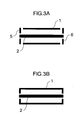
- One is based on a configuration in which an electrically conductive cap-shaped lid electrode is arranged on end of the hollow-cylindrical electrode formed outside.
- the cap-shaped lid electrodes are of course electrically conducted to the hollow-cylindrical electrode.
- the resulting deformation of the electric field can contain the ions in the trapping area. The detail is described in the first embodiment later.
- the second method consists in applying an electrostatic voltage to each of the lid electrodes independently at the ends of the hollow-cylindrical electrode without conduction with the hollow-cylindrical electrode.
- a positive potential is applied to both the hollow-cylindrical electrode and the solid-cylindrical electrode, while negative ions are trapped by applying a negative potential to both the hollow-cylindrical electrode the solid-cylindrical electrode.
- target ions having a certain m/z identified by mass spectrometry are isolated by changing the radio frequency and the electrostatic voltage, so that ions other than those making up the target ions are bombarded with the hollow- and solid-cylindrical electrodes while leaving the target ions alone.
- the position at which the ions exist is calculated.
- the value m/z of the target ions is known as explained above with reference to the principle of the one-dimensional ion trap, and therefore, the position at which ions having the m/z value are trapped can be determined by calculations to measure the ion mobility.
- the radio frequency voltage is reduced to zero instantaneously. Then, only the inward force due to the electrostatic voltage is applied to the ions, and therefore, the ions begin the motion toward the solid-cylindrical electrode. Since the probability that the ions and the gas bombard each other depends on the size (sectional area) of the ions. Therefore, the time before arriving at the electrode, which is affected by the bombardment with the gas in the one-dimensional ion trap, depends on the size of the ions. Based on this time, an ion species having the same m/z but a different ion size is distinguished.
- the electrostatic voltage but not the radio frequency voltage to zero after the preparatory process, only the outward force due to the radio frequency voltage is applied to the ions, so that the ions begin the motion toward the hollow-cylindrical electrode.
- the time required before arrival at the electrode which is affected by the bombardment with the gas in the one-dimensional ion trap, depends on the size of the ions, and therefore, the ion species having the same m/z but different sizes can be distinguished.
- the mass spectrometric analysis method and the ion mobility method described above are based on the static phenomenon free of resonance vibration of ions, and therefore, can work even in low vacuum. Also, in view of the fact that a greater amount of ions than in the prior art can be stored as described above with reference to the principle of the one-dimensional ion trap, the high-sensitivity ion detection means such as the electron multiplier is not required, and the ion quantity can be measured simply by detecting the ion current.
- the mass spectrometry with a simple exhaust system not requiring the high vacuum required in the prior art can be realized. Also, the fact that the operation in low vacuum is possible eliminates the need of the differential exhaust system connecting to a high vacuum area conventionally required for introducing the specimen ions generated in the atmosphere into the ion trap. In other words, ions can be introduced with a high efficiency, and therefore, at high speed into the one-dimensional ion trap according to this invention.
- a compact, inexpensive and simple mass spectrometry means is realized in view of the facts that the operation in low vacuum is possible and no high vacuum is required unlike in the prior art, that a compact structure having a smaller number of electrodes can be machined easily, and that ions can be detected by detecting the ion current without amplification in the electron multiplier or the like.
- the ion mobility analysis means has so far been used in this pressure region, the method according to this invention can provide the true mass spectrometric analysis means, thereby improving the analysis accuracy in various applications. Further, both the mass spectrometry can be conducted and the ion mobility can be measured in the same ion trap, and therefore, the analysis higher in accuracy is made possible.
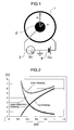
- a radio frequency voltage (amplitude Vrf, frequency ⁇ /2 ⁇ ) is applied to the solid-cylindrical electrode using a radio frequency voltage power supply 3, where the DC bias of the rf voltage should be zero, while a DC voltage (Udc) is applied to the hollow-cylindrical electrode using a DC voltage power supply 4, where the rf voltage of the DC voltage should be zero.
- a radio frequency voltage (amplitude Vrf, frequency ⁇ /2 ⁇ ) is applied to the solid-cylindrical electrode using a radio frequency voltage power supply 3, where the DC bias of the rf voltage should be zero
- Udc DC voltage
- the aforementioned arrangement in terms of voltage is shown in Fig. 1 .
- this equation employs the pseudo-potential method generally used in the radio frequency ion trap theory.
- This equation is formed of two parts on the right side including the first term representing the pseudo-potential due to the radio frequency and the second term the potential due to the electrostatic voltage. This is illustrated in Fig. 2 .
- the pseudo-potential applies the outward force from the center axis to the ions and has no effect on the polarity of the ions.
- the electrostatic voltage is adapted to apply the force toward the center axis to the ions.
- the DC voltage Udc is positive in the case where positive ions are trapped, and negative in the case where negative ions are trapped.
- the potential equal to the sum of the two potentials, i.e.
- Equation (2) the potential given by Equation (2) is also shown in Fig. 2 .
- the potential of the one-dimensional ion trap according to this invention has a local minimum value, and from Equation (2), the position assuming the particular local minimum value is given by Equation (3) below.
- r min ( Ze 4 ⁇ m ⁇ ⁇ 2 ⁇ 1 log r 2 / r 1 ⁇ V rf 2 U dc ⁇ ) 1 / 2
- the polarity of Udc is of course required to be determined with respect to the polarity of ions as described above.
- Equation (3) it is understood that ions having a large m/z value are located inside near the center axis and ions having a small m/z value outside far from the center axis.
- this method is called the one-dimensional trap.
- m/z value in which ions can be trapped is determined by the values of the radio frequency voltage and the electrostatic voltage. In other words, ions that can be trapped have a stable area unique thereto. This fact is derived from the condition that "there must exist a stable point of ions given by Equation (3) between inner and outer electrodes; Otherwise, ions would bombard the electrodes". Specifically, the relation holds that r 1 ⁇ r min ⁇ r 2 The condition that the solid-cylindrical electrode is not bombarded by ions leads to Equation (5).
- m 1 ZeV rf 2 2 ⁇ ⁇ 2 ⁇ U dc ⁇ 1 r 1 2 ⁇ log r 2 / r 1
- Radio frequency amplitude 200 V (2 MHz)
- Length 90 mm
- This ion trap is considered applicable to various environmental pollution substances, illegal drugs and hazardous objects.
- the valence number Z of ions often assumes unity, and therefore, ions having the molecular weight of about 13 to 1300 can be trapped. This range covers the molecular weight of all the molecules to be detected in these applications.
- ions are trapped by applying a DC electric field to the wall electrodes by a DC voltage.
- the electromagnetic wave due to RF can be prevented from leaking out of the electrodes, and as compared with the means (1), the number of parts is reduced, thereby providing a method that can be implemented at low cost.
- the method according to this embodiment has the great features described below.
- the ion trap according to this embodiment can be set to the vacuum degree of 1 Torr (0.01 Pa) which can be easily realized by what is called the roughing vacuum pump (the low vacuum pump such as the rotary pump or the diaphragm pump, the turbo molecular pump for realizing a high vacuum may not be used).
- the relation between vacuum degree and viscous resistance is such that the value of a typical ion mobility K is 0.8 to 2.4 cm ⁇ 2/V/sec (for 14 to 500 amu @ ambient pressure).
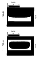
- Fig. 5 shows the result of calculating the trajectory of ions introduced from the hollow-cylindrical electrode under the conditions specified by " Ion Mobility Spectrometry", G.A. Eicemann & Z. Karpas, CRC Press. 2005 .
- (1) designates a case in which m / z is 20, (2) a case in which m / z is 200, (3) a case in which m/z is 1000, and (4) a case in which m / z is 1500.
- the radius at which ions are located is equal to the value given by Equation (3).
- the conditions are unstable, and therefore, ions are lost by bombarding the electrodes.
- Ions can be introduced still faster by increasing Vrf and Udc and thus deepening the potential not to change the stable ion position.
- the shape of the potential remains unchanged by holding the relation Vrf ⁇ 2 ⁇ Udc.
- ions having a specified m / z can also be isolated by use of Equations (3) and (4) in the one-dimensional ion trap according to this embodiment.
- the radio frequency voltage or the electrostatic voltage is changed thereby to approach the stability boundary m1 (heavy side) or m2 (light side).
- m1 dashed side
- m2 light side
- the approach to m1 a large m / z value is excluded, while the approach to m2 eliminates ions having a small m/z value.
- the isolation resolution can be determined by the degree to which the m/z value of the target ions can approach a stability boundary.
- the instability in the trap conditions is utilized as a mass spectrometric analysis method.
- stable ions trapped are instabilized (i.e. instabilized in mass selectivity) by controlling and changing the voltage condition, and the electron current generated by bombarding the electrode is measured by the ampere meter. In this way, the m/z value and the quantity of the trapped ions are measured.
- This operation has the feature that the mass spectrometry conducted using the static stability conditions of ions makes possible the analysis independent of the gas pressure.
- the operation is possible in low vacuum.
- low vacuum is generally defined as about 1 to 10 -6 Torr, while the term “high vacuum” about 10 -6 to 10 -8 Torr.
- high vacuum about 10 -6 to 10 -8 Torr.
- the resonance vibration of ions is utilized, and therefore, the bombardment of the gas has so large an effect on the resolution that the low-vacuum operation is impossible and a high vacuum is required.
- two ion detection methods described below are available for carrying out the mass spectrometry using the one-dimensional ion trap according to this embodiment.
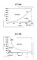
- Fig. 6A shows the calculation result in the case where ions are detected by scanning the radio frequency amplitude.
- the line designated by A1 indicates the m / z value with ions bombarding the solid-cylindrical electrode 2 and the line designated by A2 the m/z value with ions bombarding the hollow-cylindrical electrode 1.
- the ions existing in the area defined by the two lines are stably trapped, while ions existing in other than this stable area bombard the solid-cylindrical electrode or the hollow-cylindrical electrode and fail to be trapped in stable condition.
- Fig. 6B shows the calculation result in the case where the electrostatic voltage is scanned to detect ions.
- the line designated by B1 represents the m / z value with ions bombarding the solid-cylindrical electrode 2 and the line designated by B2 the m/z value with ions bombarding the hollow-cylindrical electrode 1.
- the ions existing in the area defined by the two lines are stably trapped, while the ions existing in other than this stable area bombard the solid-cylindrical electrode or the hollow-cylindrical electrode and fail to be trapped in stable condition.
- Line Al the calculation result for a method to detect the ion current with the solid-cylindrical electrode (inner electrode) while scanning the radio frequency amplitude due to this line is substantially linear and considered easy to detect.
- the mass spectrometric analysis operation is basically possible also by other methods.
- Line A2 represents a case in which the radio frequency amplitude is scanned to detect ions with the hollow-cylindrical electrode (outer electrode). The case is also applicable, though narrow in the mass range in which instability increases with respect to the scanning amount of the radio frequency amplitude.
- Line B1 represents a case in which the DC voltage is scanned to detect ions on the solid-cylindrical electrode.
- the ion trap portion includes a hollow-cylindrical electrode 1, a solid-cylindrical electrode 2, insulating members 7, 8 for isolating the two electrodes from each other and supporting the solid-cylindrical electrode 2, a vacuum bath 9 for accommodating these trap electrodes, a vacuum pump 10, an ion source 11 and a pipe 12 for introducing the ions generated in the ion source to the vacuum bath.
- the radio frequency power supply 3 shown in Fig. 1 includes such elements as a oscillator 15, a multiplier 17, a radio frequency amplifier 18, a step-up radio frequency transformer 19, a RF amplitude monitor circuit 20, capacitors 21, 22 and a feedback amplifier 16.
- the current monitor circuit includes a current amplifier 23.
- the radio frequency amplitude and the electrostatic voltage are controlled and the current value read by a digital/analog converter 14 controlled by a computer 13.
- the vacuum pump 10 is a diaphragm pump.
- the radio frequency amplitude control voltage generated by the converter 14 in response to a command from the computer 13 is multiplied by the signal of the oscillator 15 through the feedback amplifier 16, and the amplitude-controlled radio frequency signal is input to the radio frequency amplifier 18.
- the power-amplified radio frequency signal is further amplified by the transformer 19 and input to the solid-cylindrical electrode 2.
- the amplitude of the voltage at the output end of the transformer 19 is converted into a low electrostatic voltage and input to the feedback amplifier 16.
- This circuit makings up a negative feedback circuit, is controlled in such a manner that the output voltage of the transformer 19 is always proportional to the control voltage output from the converter 14.
- the output signal of the oscillator 15 may assume a rectangular wave or, more preferably, a sinusoidal wave,. This is by reason of the fact that the transformer 19 and the ion trap electrode make up a resonance circuit and only the resonant sinusoidal wave component is amplified, so that the voltage applied to the ion trap actually assumes a sinusoidal wave.
- the A1 mode described above is most preferable as an analysis process.
- the radio frequency amplitude is set to a value as large as about 200 V and the ions generated by the ion source are trapped. About one millisecond later, the ions enter an equilibrium state, and therefore, the radio frequency amplitude is scanned downward. Then, the outward force due to the radio frequency is reduced and the ions move toward the center. Once the ions bombard the electrode, the ion quantity is detected as an ion current. As described above, by measuring the ion current with respect to the radio frequency amplitude, a mass spectrum can be obtained. The radio frequency amplitude is converted to the m / z value of ions according to Equation (3).
- the mass analysis operation (second embodiment) is performed to determine the m/z value of target ions.
- the ion species is isolated by the method described in the first embodiment.
- the isolated ions are set to a high voltage at a radio frequency amplitude to locate it in the neighborhood of the outside of the ion trap to lengthen the drift distance.
- the voltage Vrf is turned off instantaneously, and ions having a large ion mobility K bombard the solid-cylindrical electrode before the remaining ions.
- the time difference between the time during which the radio frequency is turned off and the time when the ion current is measured indicates the ion mobility.
- the two-dimensional measurement of the mass-to-charge ratio and the ion mobility of the specimen ions is made possible.
- the ion mobility can be measured by detecting the current on the hollow-cylindrical electrode with the electrostatic voltage instantaneously turned off.
- Fig. 8 shows two calculation results for 50 % different values of the ion mobility K.
- the ion m/z value is 200 and the electrostatic voltage of 1 V is applied.
- the trajectory shown in (1) is 50 % larger in ion mobility than the trajectory shown in (2). In this way, the time before reaching the surface of the solid-cylindrical electrode (indicated by dotted line) is varied with K, and therefore, ions different in mobility in spite of the same m/z value can be distinguished.
Landscapes
- Chemical & Material Sciences (AREA)
- Physics & Mathematics (AREA)
- Analytical Chemistry (AREA)
- Life Sciences & Earth Sciences (AREA)
- Electrochemistry (AREA)
- Health & Medical Sciences (AREA)
- Chemical Kinetics & Catalysis (AREA)
- Spectroscopy & Molecular Physics (AREA)
- Biochemistry (AREA)
- General Health & Medical Sciences (AREA)
- General Physics & Mathematics (AREA)
- Immunology (AREA)
- Pathology (AREA)
- Other Investigation Or Analysis Of Materials By Electrical Means (AREA)
- Electron Tubes For Measurement (AREA)
Applications Claiming Priority (1)
| Application Number | Priority Date | Filing Date | Title |
|---|---|---|---|
| JP2007171378A JP4905270B2 (ja) | 2007-06-29 | 2007-06-29 | イオントラップ、質量分析計、イオンモビリティ分析計 |
Publications (3)
| Publication Number | Publication Date |
|---|---|
| EP2015345A2 true EP2015345A2 (de) | 2009-01-14 |
| EP2015345A3 EP2015345A3 (de) | 2010-11-03 |
| EP2015345B1 EP2015345B1 (de) | 2013-10-23 |
Family
ID=40070962
Family Applications (1)
| Application Number | Title | Priority Date | Filing Date |
|---|---|---|---|
| EP08009516.9A Not-in-force EP2015345B1 (de) | 2007-06-29 | 2008-05-23 | Ionen-Mobilitäts-Spektrometer mit einer Ionenfalle |
Country Status (4)
| Country | Link |
|---|---|
| US (1) | US20090001265A1 (de) |
| EP (1) | EP2015345B1 (de) |
| JP (1) | JP4905270B2 (de) |
| CN (1) | CN101335177B (de) |
Cited By (1)
| Publication number | Priority date | Publication date | Assignee | Title |
|---|---|---|---|---|
| WO2017112938A1 (en) * | 2015-12-23 | 2017-06-29 | University Of Maryland, College Park | Active stabilization of ion trap radiofrequency potentials |
Families Citing this family (15)
| Publication number | Priority date | Publication date | Assignee | Title |
|---|---|---|---|---|
| JP5323384B2 (ja) * | 2008-04-14 | 2013-10-23 | 株式会社日立製作所 | 質量分析計および質量分析方法 |
| KR101711145B1 (ko) | 2010-09-03 | 2017-03-13 | 삼성전자주식회사 | 휴대용 4중극자 이온트랩 질량분석기 |
| GB201114735D0 (en) * | 2011-08-25 | 2011-10-12 | Micromass Ltd | Mass spectrometer |
| GB201117158D0 (en) * | 2011-10-05 | 2011-11-16 | Micromass Ltd | Ion guide |
| US8637817B1 (en) | 2013-03-01 | 2014-01-28 | The Rockefeller University | Multi-pole ion trap for mass spectrometry |
| CA2903941A1 (en) * | 2013-03-13 | 2014-09-18 | Micromass Uk Limited | Coaxial ion guide |
| US8878127B2 (en) * | 2013-03-15 | 2014-11-04 | The University Of North Carolina Of Chapel Hill | Miniature charged particle trap with elongated trapping region for mass spectrometry |
| JP5997650B2 (ja) * | 2013-04-15 | 2016-09-28 | 株式会社日立ハイテクノロジーズ | 分析システム |
| CN106199195A (zh) * | 2016-07-19 | 2016-12-07 | 牛明慧 | 印刷电路板离子迁移测试系统 |
| WO2018087634A1 (en) * | 2016-11-11 | 2018-05-17 | Dh Technologies Development Pte. Ltd. | Spatial, mass and energy focused ion injection method and device |
| GB201814681D0 (en) * | 2018-09-10 | 2018-10-24 | Micromass Ltd | ION Filtering devices |
| JP2019091700A (ja) * | 2019-01-04 | 2019-06-13 | 908 デバイセズ インク.908 Devices Inc. | コンパクトな質量分析計 |
| CN110672712A (zh) * | 2019-10-22 | 2020-01-10 | 哈尔滨工业大学 | 一种基于圆柱电极的大气离子迁移率测量装置及方法 |
| CN114628220B (zh) * | 2022-01-27 | 2024-08-09 | 清华大学 | 真空离子富集方法 |
| CN115047259B (zh) * | 2022-04-15 | 2022-12-06 | 安徽省太微量子科技有限公司 | 基于频率可调二维线性离子阱的颗粒荷质比测量方法 |
Citations (1)
| Publication number | Priority date | Publication date | Assignee | Title |
|---|---|---|---|---|
| US2939952A (en) | 1953-12-24 | 1960-06-07 | Paul | Apparatus for separating charged particles of different specific charges |
Family Cites Families (19)
| Publication number | Priority date | Publication date | Assignee | Title |
|---|---|---|---|---|
| GB1404386A (en) * | 1972-06-28 | 1975-08-28 | Unisearch Ltd | Extended monopole spectrometers and filters |
| WO2000008456A1 (en) * | 1998-08-05 | 2000-02-17 | National Research Council Canada | Method for separation and enrichment of isotopes in gaseous phase |
| US6251282B1 (en) * | 1998-11-16 | 2001-06-26 | Archimedes Technology Group, Inc. | Plasma filter with helical magnetic field |
| EP1273029B8 (de) * | 2000-03-14 | 2006-01-11 | National Research Council Canada | Faims apparatur und verfahren mit lasergestützter ionisationsquelle |
| GB0220450D0 (en) * | 2002-09-03 | 2002-10-09 | Micromass Ltd | Mass spectrometer |
| AU2003260773A1 (en) * | 2002-09-03 | 2004-03-29 | Micromass Uk Limited | Mass spectrometer |
| US6838666B2 (en) * | 2003-01-10 | 2005-01-04 | Purdue Research Foundation | Rectilinear ion trap and mass analyzer system and method |
| CN1788327A (zh) * | 2003-01-10 | 2006-06-14 | 珀杜研究基金会 | 直线式离子阱及质量分析器系统和方法 |
| EP1651949A4 (de) * | 2003-06-20 | 2010-01-20 | Univ Brigham Young | Einzelvorrichtung zur ionenmobilitäts- und ionenfallen-massenspektrometrie |
| US7057166B2 (en) * | 2003-06-27 | 2006-06-06 | Ionalytics Corporation | Method of separating ions |
| GB0513047D0 (en) * | 2005-06-27 | 2005-08-03 | Thermo Finnigan Llc | Electronic ion trap |
| CN1832101A (zh) * | 2006-03-23 | 2006-09-13 | 复旦大学 | 一种线性离子阱-飞行时间质谱分析仪器 |
| US20070278398A1 (en) * | 2006-05-30 | 2007-12-06 | Gangqiang Li | Ion mobility spectrometry waveform |
| US8849278B2 (en) * | 2007-01-07 | 2014-09-30 | Jeffrey Bush | Mobile device activation |
| US8666366B2 (en) * | 2007-06-22 | 2014-03-04 | Apple Inc. | Device activation and access |
| US9451450B2 (en) * | 2007-09-01 | 2016-09-20 | Apple Inc. | Postponed carrier configuration |
| US8032181B2 (en) * | 2007-09-01 | 2011-10-04 | Apple Inc. | Service provider activation with subscriber identity module policy |
| US8442521B2 (en) * | 2007-09-04 | 2013-05-14 | Apple Inc. | Carrier configuration at activation |
| JP5323384B2 (ja) * | 2008-04-14 | 2013-10-23 | 株式会社日立製作所 | 質量分析計および質量分析方法 |
-
2007
- 2007-06-29 JP JP2007171378A patent/JP4905270B2/ja not_active Expired - Fee Related
-
2008
- 2008-05-22 US US12/153,636 patent/US20090001265A1/en not_active Abandoned
- 2008-05-23 EP EP08009516.9A patent/EP2015345B1/de not_active Not-in-force
- 2008-05-23 CN CN200810109182.0A patent/CN101335177B/zh not_active Expired - Fee Related
Patent Citations (1)
| Publication number | Priority date | Publication date | Assignee | Title |
|---|---|---|---|---|
| US2939952A (en) | 1953-12-24 | 1960-06-07 | Paul | Apparatus for separating charged particles of different specific charges |
Non-Patent Citations (2)
| Title |
|---|
| R.E. MARCH; R.J.HUGHES: "Quadrupole Storage Mass Spectrometry", JOHN WILEY AND SONS |
| RAYMOND E. MARCH; JOHN F. TODD.: "Quadrupole Ion Trap Mass Spectrometry", WILEY-INTERSCIENCE |
Cited By (3)
| Publication number | Priority date | Publication date | Assignee | Title |
|---|---|---|---|---|
| WO2017112938A1 (en) * | 2015-12-23 | 2017-06-29 | University Of Maryland, College Park | Active stabilization of ion trap radiofrequency potentials |
| US9991105B2 (en) | 2015-12-23 | 2018-06-05 | University Of Maryland, College Park | Active stabilization of ion trap radiofrequency potentials |
| US10262849B2 (en) | 2015-12-23 | 2019-04-16 | University Of Maryland | Active stabilization of ion trap radiofrequency potentials |
Also Published As
| Publication number | Publication date |
|---|---|
| JP2009009863A (ja) | 2009-01-15 |
| JP4905270B2 (ja) | 2012-03-28 |
| CN101335177B (zh) | 2010-06-09 |
| CN101335177A (zh) | 2008-12-31 |
| EP2015345B1 (de) | 2013-10-23 |
| EP2015345A3 (de) | 2010-11-03 |
| US20090001265A1 (en) | 2009-01-01 |
Similar Documents
| Publication | Publication Date | Title |
|---|---|---|
| EP2015345B1 (de) | Ionen-Mobilitäts-Spektrometer mit einer Ionenfalle | |
| US6452168B1 (en) | Apparatus and methods for continuous beam fourier transform mass spectrometry | |
| US10755915B2 (en) | Microscale mass spectrometry systems, devices and related methods | |
| Makarov | Electrostatic axially harmonic orbital trapping: a high-performance technique of mass analysis | |
| JP5323384B2 (ja) | 質量分析計および質量分析方法 | |
| US7755040B2 (en) | Mass spectrometer and electric field source for mass spectrometer | |
| US8716654B2 (en) | Electrostatic trap | |
| US7199362B2 (en) | Cross-flow ion mobility analyzer | |
| WO1999047912A1 (en) | Ion mobility storage trap and method | |
| USRE38138E1 (en) | Method for linearization of ion currents in a quadrupole mass analyzer | |
| US20130001415A1 (en) | Frequency scan linear ion trap mass spectrometry | |
| US4933547A (en) | Method for external calibration of ion cyclotron resonance mass spectrometers | |
| US5793038A (en) | Method of operating an ion trap mass spectrometer | |
| US20160163529A1 (en) | Frequency scan linear ion trap mass spectrometry | |
| US6573495B2 (en) | High capacity ion cyclotron resonance cell | |
| JP6593451B2 (ja) | 四重極マスフィルタ及び四重極型質量分析装置 | |
| JP7340695B2 (ja) | 質量分析装置の制御方法、質量分析システム及び電圧制御装置 | |
| RU2693570C1 (ru) | Многоэлектродная гармонизированная ионная ловушка кингдона со слившимися внутренними электродами | |
| Medhe | Mass Spectrometry: Analysers an Important Tool | |
| CN120565393A (zh) | 多端口离子槽输入的多电极协调金登阱 | |
| Paglia et al. | Traveling wave ion mobility mass spectrometry: Metabolomics applications | |
| RU2831990C1 (ru) | Многоэлектродная гармонизированная ловушка кингдона с многопортовым вводом ионов через щель | |
| EP4042469B1 (de) | Ionenfalle mit toroidförmiger ionenspeicherzelle und massenspektrometer | |
| JP2018181474A (ja) | 四重極型質量分析方法及び四重極型質量分析装置 | |
| CN114235937A (zh) | 一种在质谱仪离子阱中同时检测正离子与负离子的方法 |
Legal Events
| Date | Code | Title | Description |
|---|---|---|---|
| PUAI | Public reference made under article 153(3) epc to a published international application that has entered the european phase |
Free format text: ORIGINAL CODE: 0009012 |
|
| 17P | Request for examination filed |
Effective date: 20080619 |
|
| AK | Designated contracting states |
Kind code of ref document: A2 Designated state(s): AT BE BG CH CY CZ DE DK EE ES FI FR GB GR HR HU IE IS IT LI LT LU LV MC MT NL NO PL PT RO SE SI SK TR |
|
| AX | Request for extension of the european patent |
Extension state: AL BA MK RS |
|
| PUAL | Search report despatched |
Free format text: ORIGINAL CODE: 0009013 |
|
| AK | Designated contracting states |
Kind code of ref document: A3 Designated state(s): AT BE BG CH CY CZ DE DK EE ES FI FR GB GR HR HU IE IS IT LI LT LU LV MC MT NL NO PL PT RO SE SI SK TR |
|
| AX | Request for extension of the european patent |
Extension state: AL BA MK RS |
|
| AKX | Designation fees paid |
Designated state(s): DE FR GB IT |
|
| REG | Reference to a national code |
Ref country code: DE Ref legal event code: R079 Ref document number: 602008028227 Country of ref document: DE Free format text: PREVIOUS MAIN CLASS: H01J0049420000 Ipc: G01N0027620000 |
|
| GRAP | Despatch of communication of intention to grant a patent |
Free format text: ORIGINAL CODE: EPIDOSNIGR1 |
|
| RIC1 | Information provided on ipc code assigned before grant |
Ipc: H01J 49/42 20060101ALI20130416BHEP Ipc: G01N 27/62 20060101AFI20130416BHEP |
|
| INTG | Intention to grant announced |
Effective date: 20130513 |
|
| GRAS | Grant fee paid |
Free format text: ORIGINAL CODE: EPIDOSNIGR3 |
|
| GRAA | (expected) grant |
Free format text: ORIGINAL CODE: 0009210 |
|
| AK | Designated contracting states |
Kind code of ref document: B1 Designated state(s): DE FR GB IT |
|
| REG | Reference to a national code |
Ref country code: GB Ref legal event code: FG4D |
|
| REG | Reference to a national code |
Ref country code: DE Ref legal event code: R096 Ref document number: 602008028227 Country of ref document: DE Effective date: 20131219 |
|
| REG | Reference to a national code |
Ref country code: DE Ref legal event code: R097 Ref document number: 602008028227 Country of ref document: DE |
|
| PLBE | No opposition filed within time limit |
Free format text: ORIGINAL CODE: 0009261 |
|
| STAA | Information on the status of an ep patent application or granted ep patent |
Free format text: STATUS: NO OPPOSITION FILED WITHIN TIME LIMIT |
|
| 26N | No opposition filed |
Effective date: 20140724 |
|
| REG | Reference to a national code |
Ref country code: DE Ref legal event code: R097 Ref document number: 602008028227 Country of ref document: DE Effective date: 20140724 |
|
| REG | Reference to a national code |
Ref country code: FR Ref legal event code: PLFP Year of fee payment: 8 |
|
| PGFP | Annual fee paid to national office [announced via postgrant information from national office to epo] |
Ref country code: GB Payment date: 20150520 Year of fee payment: 8 Ref country code: DE Payment date: 20150519 Year of fee payment: 8 |
|
| PGFP | Annual fee paid to national office [announced via postgrant information from national office to epo] |
Ref country code: IT Payment date: 20150515 Year of fee payment: 8 Ref country code: FR Payment date: 20150508 Year of fee payment: 8 |
|
| REG | Reference to a national code |
Ref country code: DE Ref legal event code: R119 Ref document number: 602008028227 Country of ref document: DE |
|
| GBPC | Gb: european patent ceased through non-payment of renewal fee |
Effective date: 20160523 |
|
| PG25 | Lapsed in a contracting state [announced via postgrant information from national office to epo] |
Ref country code: IT Free format text: LAPSE BECAUSE OF NON-PAYMENT OF DUE FEES Effective date: 20160523 |
|
| REG | Reference to a national code |
Ref country code: FR Ref legal event code: ST Effective date: 20170131 |
|
| PG25 | Lapsed in a contracting state [announced via postgrant information from national office to epo] |
Ref country code: FR Free format text: LAPSE BECAUSE OF NON-PAYMENT OF DUE FEES Effective date: 20160531 Ref country code: DE Free format text: LAPSE BECAUSE OF NON-PAYMENT OF DUE FEES Effective date: 20161201 |
|
| PG25 | Lapsed in a contracting state [announced via postgrant information from national office to epo] |
Ref country code: GB Free format text: LAPSE BECAUSE OF NON-PAYMENT OF DUE FEES Effective date: 20160523 |