EP2015411A2 - Verfahren zum Betreiben eines oberflächenemittierenden Halbleiterlasers, optisches Übertragungsmodul und tragbare elektronische Vorrichtung - Google Patents
Verfahren zum Betreiben eines oberflächenemittierenden Halbleiterlasers, optisches Übertragungsmodul und tragbare elektronische Vorrichtung Download PDFInfo
- Publication number
- EP2015411A2 EP2015411A2 EP08152725A EP08152725A EP2015411A2 EP 2015411 A2 EP2015411 A2 EP 2015411A2 EP 08152725 A EP08152725 A EP 08152725A EP 08152725 A EP08152725 A EP 08152725A EP 2015411 A2 EP2015411 A2 EP 2015411A2
- Authority
- EP
- European Patent Office
- Prior art keywords
- driving
- current
- internal resistance
- current value
- surface emitting
- Prior art date
- Legal status (The legal status is an assumption and is not a legal conclusion. Google has not performed a legal analysis and makes no representation as to the accuracy of the status listed.)
- Granted
Links
- 238000000034 method Methods 0.000 title claims abstract description 33
- 230000003287 optical effect Effects 0.000 title claims description 67
- 230000005540 biological transmission Effects 0.000 title claims description 60
- 239000004065 semiconductor Substances 0.000 claims abstract description 48
- 230000007423 decrease Effects 0.000 claims abstract description 12
- 230000008878 coupling Effects 0.000 claims description 4
- 238000010168 coupling process Methods 0.000 claims description 4
- 238000005859 coupling reaction Methods 0.000 claims description 4
- 239000010410 layer Substances 0.000 description 23
- 238000010586 diagram Methods 0.000 description 5
- 239000013308 plastic optical fiber Substances 0.000 description 5
- 230000009467 reduction Effects 0.000 description 5
- 229910001218 Gallium arsenide Inorganic materials 0.000 description 3
- 230000002411 adverse Effects 0.000 description 3
- 230000000694 effects Effects 0.000 description 3
- 239000010408 film Substances 0.000 description 3
- 239000011229 interlayer Substances 0.000 description 3
- 239000013307 optical fiber Substances 0.000 description 3
- 230000008054 signal transmission Effects 0.000 description 3
- 238000003491 array Methods 0.000 description 2
- 239000002131 composite material Substances 0.000 description 2
- 238000004590 computer program Methods 0.000 description 2
- 230000000630 rising effect Effects 0.000 description 2
- 125000006850 spacer group Chemical group 0.000 description 2
- 229910004205 SiNX Inorganic materials 0.000 description 1
- 230000003321 amplification Effects 0.000 description 1
- 239000000919 ceramic Substances 0.000 description 1
- 230000004069 differentiation Effects 0.000 description 1
- 230000006870 function Effects 0.000 description 1
- 238000003384 imaging method Methods 0.000 description 1
- 238000012986 modification Methods 0.000 description 1
- 230000004048 modification Effects 0.000 description 1
- 238000003199 nucleic acid amplification method Methods 0.000 description 1
- 239000011347 resin Substances 0.000 description 1
- 229920005989 resin Polymers 0.000 description 1
- 239000000758 substrate Substances 0.000 description 1
- 239000010409 thin film Substances 0.000 description 1
Images


Classifications
-
- H—ELECTRICITY
- H04—ELECTRIC COMMUNICATION TECHNIQUE
- H04B—TRANSMISSION
- H04B10/00—Transmission systems employing electromagnetic waves other than radio-waves, e.g. infrared, visible or ultraviolet light, or employing corpuscular radiation, e.g. quantum communication
- H04B10/50—Transmitters
- H04B10/501—Structural aspects
- H04B10/503—Laser transmitters
- H04B10/504—Laser transmitters using direct modulation
-
- H—ELECTRICITY
- H01—ELECTRIC ELEMENTS
- H01S—DEVICES USING THE PROCESS OF LIGHT AMPLIFICATION BY STIMULATED EMISSION OF RADIATION [LASER] TO AMPLIFY OR GENERATE LIGHT; DEVICES USING STIMULATED EMISSION OF ELECTROMAGNETIC RADIATION IN WAVE RANGES OTHER THAN OPTICAL
- H01S5/00—Semiconductor lasers
- H01S5/04—Processes or apparatus for excitation, e.g. pumping, e.g. by electron beams
- H01S5/042—Electrical excitation ; Circuits therefor
- H01S5/0427—Electrical excitation ; Circuits therefor for applying modulation to the laser
-
- H—ELECTRICITY
- H01—ELECTRIC ELEMENTS
- H01S—DEVICES USING THE PROCESS OF LIGHT AMPLIFICATION BY STIMULATED EMISSION OF RADIATION [LASER] TO AMPLIFY OR GENERATE LIGHT; DEVICES USING STIMULATED EMISSION OF ELECTROMAGNETIC RADIATION IN WAVE RANGES OTHER THAN OPTICAL
- H01S5/00—Semiconductor lasers
- H01S5/06—Arrangements for controlling the laser output parameters, e.g. by operating on the active medium
- H01S5/068—Stabilisation of laser output parameters
- H01S5/06812—Stabilisation of laser output parameters by monitoring or fixing the threshold current or other specific points of the L-I or V-I characteristics
-
- H—ELECTRICITY
- H01—ELECTRIC ELEMENTS
- H01S—DEVICES USING THE PROCESS OF LIGHT AMPLIFICATION BY STIMULATED EMISSION OF RADIATION [LASER] TO AMPLIFY OR GENERATE LIGHT; DEVICES USING STIMULATED EMISSION OF ELECTROMAGNETIC RADIATION IN WAVE RANGES OTHER THAN OPTICAL
- H01S5/00—Semiconductor lasers
- H01S5/10—Construction or shape of the optical resonator, e.g. extended or external cavity, coupled cavities, bent-guide, varying width, thickness or composition of the active region
- H01S5/18—Surface-emitting [SE] lasers, e.g. having both horizontal and vertical cavities
- H01S5/183—Surface-emitting [SE] lasers, e.g. having both horizontal and vertical cavities having only vertical cavities, e.g. vertical cavity surface-emitting lasers [VCSEL]
- H01S5/18308—Surface-emitting [SE] lasers, e.g. having both horizontal and vertical cavities having only vertical cavities, e.g. vertical cavity surface-emitting lasers [VCSEL] having a special structure for lateral current or light confinement
- H01S5/18311—Surface-emitting [SE] lasers, e.g. having both horizontal and vertical cavities having only vertical cavities, e.g. vertical cavity surface-emitting lasers [VCSEL] having a special structure for lateral current or light confinement using selective oxidation
Definitions
- This invention relates to a method for driving a surface emitting semiconductor laser, an optical transmission module, and a handheld electronic device.
- a surface emitting semiconductor laser (Vertical-Cavity Surface-Emitting Laser diode: hereinafter referred to as VCSEL) that is designed to have a small internal resistance is typically used.
- VCSEL Vertical-Cavity Surface-Emitting Laser diode
- Some of single-mode VCSELs have an internal resistance of greater than 50 ohms; for example, an internal resistance of several hundred or several thousand ohms.
- such a high resistant VCSEL has a higher resistance than a resistance of, for example, 50 ohms, that is typically used for a driving circuit or wiring and thus causes impedance mismatching.
- JP-A-5-283791 and JP-A-2002-353568 disclose techniques that reduce the resistance of a VCSEL down to less than 50 ohms for high-speed modulation.
- JP-A-2003-101127 discloses a technique that reduces the impedance of a load by providing a resistor parallel to the semiconductor laser.
- JP-A-2004-273584 discloses a technique in which even a VCSEL having a high internal resistance can be driven at a high frequency while reflectance loss being kept small over a wide band, by providing a termination resistor interposed between a signal line and the VCSEL, and a resistor connected parallel to the VCSEL.
- JP-A-2002-335038 discloses a technique that uses a voltage driving scheme in order to drive a VCSEL, which has an internal resistance of several hundred ohms, at a high speed.
- the use of an optical transmission module in which a VCSEL is used as a light source for signal transmission has been considered.
- a major technical difficulty therein is the reduction in power consumption of the VCSEL.
- One method for reducing power is to lower the threshold current of the VCSEL and reduce the driving current.
- the threshold current is lowered, the internal resistance becomes high, and thus it becomes difficult to drive the VCSEL at a high speed.
- optical transmission module that is appropriate for reducing power consumption of handheld devices or the like.
- a method for driving a surface emitting semiconductor laser including an active region that generates light, a resonator structure disposed such that it sandwiches the active region, and a driving electrode that provides power to the active region.
- the surface emitting semiconductor laser has an internal resistance defined by voltage and current applied to the driving electrode.
- the method includes applying a modulation signal to the driving electrode, in which the modulation signal has a current amplitude defined by a first current value and a second current value that is greater than the first current value.
- the modulation signal is in a negative gradient region in which the internal resistance decreases in contrast to the increase of the current.
- the internal resistance is defined by differentiating the relation between the applied voltage and current.
- the first current value is less than an inflection point at which the decrease of the internal resistance tends toward saturation and may be greater than a threshold current of the surface emitting semiconductor laser.
- the second current value may be greater than an inflection point of the internal resistance.
- the current amplitude is equal to or less than 2 mA and the frequency of the modulation signal is equal to or greater than 1 GHz, and the distance of a transmission line that couples a driving circuit that outputs the modulation signal and a driving electrode of the surface emitting semiconductor laser is equal to or less than 2 mm.
- a first internal resistance that corresponds to the first current value may be higher than the resistance of the transmission line, the internal resistance is at least 80 ohms.
- the optical output of VCSEL corresponding to the second current value which depends on the power budget of overall of optical link, is for example greater or equal 0.4mW.
- an optical transmission module including a light sending device that includes a surface emitting semiconductor laser and a driving circuit driving the surface emitting semiconductor laser and sends an optical signal by the driving of the surface emitting semiconductor laser, an optical transmission medium that transmits an optical signal sent from the light sending device, and a light receiving device that receives an optical signal transmitted by the optical transmission medium.
- the surface emitting semiconductor laser includes an active region that generates light, a resonator structure disposed such that it sandwiches the active region, and a driving electrode that provides power to the active region.
- the surface emitting semiconductor laser has an internal resistance defined by voltage and current applied to the driving electrode, the driving electrode applies a modulation signal to the driving electrode, the modulation signal has a current amplitude defined by a first current value and a second current value that is greater than the first current value, and the modulation signal is in a negative gradient region in which the internal resistance decreases in contrast to the increase of the current.
- the driving circuit provides a modulation signal of at least 1 GHz to the surface emitting semiconductor laser, and the current amplitude of the modulation signal is equal to or less than 2 mA.
- the distance of a transmission line that couples the driving circuit and a driving electrode of the surface emitting semiconductor laser is equal to or less than 2 mm, and the optical transmission medium is equal to or less than about 30 cm preferably.
- the surface emitting semiconductor laser preferably outputs multi-mode laser light, and the optical transmission medium is a multi-mode optical transmission medium.
- a handheld electronic device includes the above mentioned optical transmission module.
- the handheld electronic device includes a body portion and a display portion coupled through a coupling portion to the body portion, and the body portion includes a light sending device, and the display portion includes a light receiving device, and the optical transmission medium passes through the coupling portion.
- the negative gradient region may be near a threshold value, and an average current value during modulation may become low current near the threshold value accordingly, thereby power reduction may be obtained.
- the use of the negative gradient region may facilitate current flow during modulation, and jitters at rising edges may become less likely to occur, and thus high-speed modulation may be performed.
- FIGs. 1A to 1C are schematic diagrams showing examples of a typical configuration of an optical transmission module according to an example of the present invention.
- an optical transmission module 10 is configured to include a light sending device 20 that sends an optical signal, an optical transmission medium 30 that transmits the sent optical signal, and a light receiving device 40 that receives the transmitted optical signal.
- the light sending device 20 is capable of converting an electrical signal into an optical signal, and is configured to include a VCSEL 50, and a driving circuit 60 for driving the VCSEL 50.
- the VCSEL 50 emits laser light having a wavelength that corresponds to a transmission distance of the optical signal. In a case where the transmission distance is short, laser light of 850 nm, for example, may be outputted.
- the laser light may be either of single-mode or multi-mode. However, for a relatively short transmission distance, it is desirable to use multi-mode laser light.
- the optical transmission medium 30 may be made of a light waveguide or an optical fiber or the like.
- a multi-mode POF plastic optical fiber
- a multi-mode light waveguide may be used. If flexibility is required for the POF, it is desirable to use a multi-core POF.
- the light receiving device 40 is capable of converting a transmitted optical signal into an electrical signal, and is configured to include a photo diode 70 that receives an optical signal and converts it into an electrical signal, and an amplifier 80 that amplifies the converted electrical signal.
- a phototransistor having an amplification function may be used instead of the photo diode 70.
- An optical transmission module 10A shown in FIG. 1B is an example of an optical-electrical composite wiring that transmits optical signals in parallel.
- a light sending and receiving device 90A includes the VCSEL 50 and the driving circuit 60 for sending an optical signal, and further includes the photo diode 70 and the amplifier 80 for receiving an optical signal.
- a light sending and receiving device 90B includes the VCSEL 50 and the driving circuit 60, and the photo diode 70 and the amplifier 80.
- the optical transmission medium 30 provides a transmission line for bi-directional optical transmission.
- FIG. 1C illustrates another configuration example of the light sending device 20.
- a light sending device 20A may include an optical system 22, such as a lens or a mirror, which collects laser light that is outputted from the VCSEL 50.
- the configurations of the light sending device, the optical transmission medium, and the light receiving device shown in FIGs. 1A to 1C described above are provided for the purposes of illustration, and it is not intended that the present invention is limited to these examples.
- the VCSEL 50 may be a single-spot type VCSEL having a single light source, or a multi-spot type VCSEL having plural light sources. If a single-spot type VCSEL is used, an optical signal that is emitted from a single light source is serially transmitted. In contrast, if multi-spot type VCSEL arrays are used, optical signals emitted from plural light sources are transmitted in parallel. In a case where each of VCSEL arrays is driven at a different wavelength, the optical transmission medium 30 can perform multiple transmissions of optical signals.
- FIG. 2 illustrates a configuration of a light sending device.
- the driving circuit 60 includes an interface (I/F) portion 100 that receives a data signal, a driving portion 110 that provides a driving current to the VCSEL 50 depending on a digital data signal received at the I/F portion 100, and a control portion 120 that controls the driving portion 110 based on a control signal or the like.
- the control portion 120 may include a sensor that detects temperatures, and a memory in which drive conditions at each of the temperatures are defined. It is desirable to provide these components in a light module; however alternatively, it is possible to provide them externally to the light module and receive the conditions as a control signal.
- the control portion 120 may control such that the light output of a VCSEL stays constant. In this case, the control portion 120 monitors an output signal from a sensor that detects the light output of the VCSEL 50.
- the driving portion 110 may be a typical current driving circuit, a voltage driving circuit, or a composite circuit thereof.
- the driving portion 110 applies a modulation signal that depends on a low level or high level of a received data signal via a transmission line 130 to the VCSEL 50.
- the frequency of the modulation signal to drive a VCSEL may be decided as appropriate depending on transmission speed or signal processing capability.
- the optical transmission module of an example of the present invention is capable of driving the VCSEL 50 at a high frequency equal to or higher than 1 GHz.
- FIGs. 3A and 3B are diagrams showing implementation examples of a VCSEL and a driving circuit.
- a semiconductor element 50A that composes the VCSEL 50 and a semiconductor element 60A that composes the driving circuit 60 are mounted on a circuit board 140, and an electrode for an output of the semiconductor element 60A is coupled through a bonding wire 130A to a driving electrode of the semiconductor element 50A.
- FIG. 3B is another implementation example.
- Semiconductor packages 50B and 60B each respectively encapsulating the semiconductor element 50A and the semiconductor element 60A with a resin or ceramic, are mounted on the circuit board 140.
- the semiconductor packages 50B and 60B may be mounted such that a bump electrode formed on a surface thereof is flip-chip mounted or face-down mounted onto a wiring pattern 130B of the circuit board 140.
- the bonding wire 130A or the wiring pattern 130B acts as the transmission line 130 from the driving circuit 60 to the VCSEL 50.
- FIG. 4 A configuration example of a VCSEL used for an example is shown in FIG. 4 that shows a configuration of the VCSEL 50 in cross section.
- semiconductor thin films are deposited on the order of an n-type lower semiconductor multilayer reflective mirror 212, an active region 214, a p-type AlAs layer 216, a p-type upper semiconductor multilayer reflective mirror 218.
- a contact layer 220 made of p-type GaAs is formed in the uppermost layer of the upper multilayer reflective mirror 218, a contact layer 220 made of p-type GaAs is formed.
- a cylindrical mesa 202 is formed from the upper multilayer reflective mirror 218 to a portion of the lower multilayer reflective mirror 212.
- the mesa 202 is thermally processed under a high temperature vapor, and an oxidized region 228 is formed at a periphery of the AlAs layer 216 in the mesa 202, thereby a light confining region, which also acts as a current confining layer, is formed in the AlAs layer 216.
- a bottom portion, a side surface, and a portion of a top portion of the mesa 202 are covered with an interlayer insulating film 222.
- a contact hole is formed in the interlayer insulating film 222, and from above thereof, a p-side electrode layer 224 is ohmic-contacted to the contact layer 220.
- a round-shaped opening 226 for emitting laser light is formed.
- the n-type lower semiconductor multilayer reflective mirror 212 may be formed by alternately stacking plural periods of, for example, Al 0.9 Ga 0.1 As and Al 0.3 Ga 0.7 As, wherein the thickness of each layer is ⁇ /4n r (where ⁇ is lasing wavelength, n r is refractive index of the medium.)
- the active region 214 may be made of, for example, an undoped lower Al 0.5 Ga 0.5 As spacer layer, an undoped quantum well active layer, and an undoped upper Al 0.5 Ga 0.5 As spacer layer.
- the p-type upper semiconductor multilayer reflective mirror 218 may be formed by alternately stacking plural periods of, for example, Al 0.9 Ga 0.1 As and Al 0.3 Ga 0.7 As, wherein the thickness of each layer is 1/4 of the wavelength in the medium.
- the low resistant p-type AlAs layer 216 is contained in the lowermost layer of the upper semiconductor multilayer reflective mirror 218, the low resistant p-type AlAs layer 216 is contained.
- the contact layer 220 for example, having a carrier concentration of 1 ⁇ 10 19 cm -3 is stacked.
- the p-side electrode layer 224 may be made of, for example, Au
- the n-side electrode layer 210 may be made of, for example, Au/Ge.
- the interlayer insulating film 222 may be made of, for example, SiNx.
- the VCSEL 50 shown in FIG. 4 is capable of outputting multi-mode laser light having a wavelength of about 850 nm.
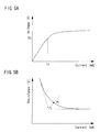
- FIG. 5A is a graph showing the relation between the driving current (horizontal axis: mA) and the driving voltage (vertical axis: V) of a VCSEL.
- FIG. 5B is a graph showing the relation between the driving current (horizontal axis: mA) and the internal resistance (vertical axis: ⁇ ) of a VCSEL.
- FIG. 5B shows the differentiation of the relation between the driving current and the driving voltage.
- the resistance shown in FIG. 5B is defined as the internal resistance of a VCSEL.
- the internal resistance of the VCSEL is extremely high, and as the driving current increases, the internal resistance decreases.
- the inflection point K is a point in a section where the internal resistance changes from a steep decrease to saturation.
- the inflection point K is defined as a point at which a bisector whose vertex is an intersection of the asymptotes and the curve of the internal resistance intersects.
- An optical transmission module of an example of the present invention is characterized in that a VCSEL having an internal resistance of, typically, about 80 ohms to 250 ohms, is used and the VCSEL is modulation-driven such that the range of the current of a modulation signal is in a negative gradient region in which the internal resistance of the VCSEL decreases in contrast to the increase of current, with a minute current amplitude generally in the negative gradient region.
- FIG. 6 is a graph illustrating a negative gradient region.
- the negative gradient region is a current region in which the current dependency of the internal resistance of a VCSEL has a negative gradient, and the range of the negative gradient region at this time is indicated as a current value I R1 . More preferably, the negative gradient region is in a range to a current value I R2 , at which the current dependency appears prominently, and is equal to or less than twice of a current value I s , around which contacts with an early negative gradient.
- FIG. 7 is a waveform of a modulation signal when a VCSEL is driven.
- the modulation signal has a current amplitude IF, which is defined by a low level current value I L and a high-level current value I H .
- the low level current value I L and the high-level current value I H are set to be in the negative gradient region shown in FIG. 6 .
- This setting is made by the control portion 120 of the driving circuit 60, and the driving circuit 60 provides the modulation signal shown in FIG. 7 through the transmission line 130 to the VCSEL 50.
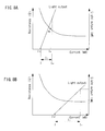
- FIG. 8A shows a method for driving a VCSEL of an example of the present invention
- FIG. 8B illustrates a method for driving a VCSEL of a related art.
- a threshold current I TH of the VCSEL of this example is set to be smaller than that of the related art.
- the gradient (slope efficiency) of the light output with respect to the driving current is made higher than that of the VCSEL of the related art.
- a desired threshold value and slope efficiency can be selected by changing a structure, such as an aperture diameter of the current confining layer 216 of the VCSEL, as appropriate. It is desirable that the slope efficiency is, for example, equal to or greater than 0.5 W/A.
- the modulation signal of this example is set to be in a negative gradient region of the internal resistance, as shown in FIG. 8A .
- the range of the current amplitude IF between the low-level current value I L and the high-level current value I H is equal to or less than 2 mA, and the low-level current value I L is smaller than the current value at the inflection point K I K of the internal resistance.
- the low-level current value I L may be slightly greater than the threshold current I TH . The purpose thereof is to enhance responsivity when the VCSEL is driven at a high speed, and the light output at this point is extremely small.
- the high-level current value I H is greater than the current value at the inflection point K I K , and preferably, smaller than the current value I R2 shown in FIG. 6 .
- the internal resistance at the low-level current value I L is equal to or greater than about 80 ohms.
- the modulation signal is not set to be in the negative gradient region of the internal resistance, as shown in FIG. 8B . That is, the low-level current value I L and the high level of the current value I H of the modulation signal is in a region in which a hyperbola of the internal resistance approximately saturates, in other words, the difference in the internal resistance between at the low-level current value I L and at the high-level current value I H is not substantially observed.
- the slope efficiency of the VCSEL is made smaller, and the current amplitude IF between the low-level current value I L and the high-level current value I H is greater than that of this example and is about 5 mA.
- a driving method of this example by using a VCSEL having an internal resistance of above 50 ohms, or typically, equal to or greater than 80 ohms, instead of a VCSEL having an internal resistance equal to or smaller than 50 ohms that has been required for high-speed driving in a related art, a VCSEL having a low threshold value and high slope efficiency can be achieved, and the VCSEL can be driven with a low current.
- a VCSEL when such a VCSEL is driven with a large amplitude current in a region in which the internal resistance saturates, it has been difficult to drive the VCSEL at high speed.
- high-speed driving can be achieved because current driving in the negative gradient region of the internal resistance is made with a small amplitude.
- the internal resistance value decreases with the increase of the current, and thus current flows more easily than in a saturation region in which the gradient is zero, and jitters at rising edges become less likely to occur, which enables high-speed modulation.
- the internal resistance near the high level at which light is emitted is relatively low, and thus light modulation at a relatively high speed can be performed.
- the modulation range of the current value is limited within a minute region in a negative gradient region, and thus high-speed modulation can be performed even when the internal resistance is generally high. It is desirable that there is a difference of equal to or greater than 20 % between the internal resistance at the high-level current value I H and the internal resistance at the low-level current value I L .
- FIG. 9 illustrates characteristics of a VCSEL of an example of the invention and a VCSEL of a related art, in further detail, and indicates the driving current on the horizontal axis and the light output on the vertical axis.
- a modulation signal of the VCSEL of this example is set to be in a negative gradient region, the negative gradient region exists in a range that includes a threshold current I TH , and thus an average current value during modulation is also low current near the threshold current I TH , which enables power reduction.
- the threshold current I TH of the VCSEL of this example is smaller than a threshold current I TH0 of the related art, and thus power reduction can be achieved from this aspect. Moreover, if the current amplitude range is simply lowered, it would adversely reduce the amount of emission light; however, by increasing the slope efficiency, it is possible to compensate for this reduction.
- the light output during modulation is indicated with P H and P L , and the slope efficiency of the VCSEL of this example is made large such that the light output becomes as same as that of the VCSEL of the related art. With such a configuration, even when low-power driving is performed, a sufficient light amount of an optical signal can be obtained.
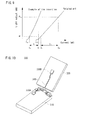
- FIG. 10 illustrates a schematic configuration of a mobile phone to which an optical transmission system of an example of the present invention is applied.
- a mobile phone 300 includes a body portion 310 on a surface of which operating buttons or the like are disposed, and a display portion 320 rotatably mounted through a hinge to the body portion 310.
- an optical transmission module as shown in FIG. 1B is mounted in the mobile phone 300.
- a light sending and receiving device 330A is provided, and in the display portion 320, a light sending and receiving device 330B is provided.
- the light sending and receiving devices 330A and 330b are coupled through a flexible optical fiber 340.
- the light sending and receiving device 330A sends image data or the like to be displayed on the display portion 320 to the light sending and receiving device 330B.
- the light sending and receiving device 330B sends image data taken with an imaging camera or the like to the light sending and receiving device 330A.
- a VCSEL emits multi-mode laser light having a wavelength of 850 nm
- the transmission line 130 from the driving circuit 60 to the VCSEL is equal to or less than 2 mm.
- the optical fiber 340 uses a POF, and the length thereof is equal to or less than 30 cm.
- the driving circuit 60 of the light sending and receiving devices 330A and 330B drives the VCSEL at a high frequency of equal to or greater than 1 GHz.
- a microstrip antenna for receiving and sending a wireless signal is mounted, and electromagnetic noises generated by the antenna may adversely affect an electrical signal.
- electromagnetic noises generated by the antenna may adversely affect an electrical signal.
- by transmitting an optical signal whose light source is a VCSEL the effects of electromagnetic noises or the like from the antenna can be minimized.
- An optical transmission module of the present invention can be especially effectively used, not only for a mobile phone as described above, but also for electronic devices such as a PDA (personal digital assistant), a laptop or notebook personal computer, or a game console.
- the optical transmission module of the present invention can be used, not only for signal transmission within an electronic device, but also for signal transmission between an electronic device and an other external electronic device.
- the various features may be implemented in hardware, or as software modules running on one or more processors.
- Features of one aspect may be applied to any of the other aspects.
- a computer program embodying the invention may be stored on a computer-readable medium, or it could, for example, be in the form of a signal such as a downloadable data signal provided from an Internet website, or it could be in any other form.
Landscapes
- Physics & Mathematics (AREA)
- Optics & Photonics (AREA)
- Electromagnetism (AREA)
- Engineering & Computer Science (AREA)
- Computer Networks & Wireless Communication (AREA)
- Signal Processing (AREA)
- Condensed Matter Physics & Semiconductors (AREA)
- General Physics & Mathematics (AREA)
- Semiconductor Lasers (AREA)
- Optical Communication System (AREA)
Applications Claiming Priority (1)
| Application Number | Priority Date | Filing Date | Title |
|---|---|---|---|
| JP2007183875A JP2009021459A (ja) | 2007-07-13 | 2007-07-13 | 面発光型半導体レーザの駆動方法および光伝送モジュール |
Publications (3)
| Publication Number | Publication Date |
|---|---|
| EP2015411A2 true EP2015411A2 (de) | 2009-01-14 |
| EP2015411A3 EP2015411A3 (de) | 2010-09-08 |
| EP2015411B1 EP2015411B1 (de) | 2012-05-16 |
Family
ID=39434122
Family Applications (1)
| Application Number | Title | Priority Date | Filing Date |
|---|---|---|---|
| EP08152725A Expired - Fee Related EP2015411B1 (de) | 2007-07-13 | 2008-03-13 | Verfahren zum Betreiben eines oberflächenemittierenden Halbleiterlasers, optisches Übertragungsmodul und tragbare elektronische Vorrichtung |
Country Status (5)
| Country | Link |
|---|---|
| US (1) | US8023539B2 (de) |
| EP (1) | EP2015411B1 (de) |
| JP (1) | JP2009021459A (de) |
| KR (1) | KR101129367B1 (de) |
| CN (1) | CN101345394B (de) |
Families Citing this family (15)
| Publication number | Priority date | Publication date | Assignee | Title |
|---|---|---|---|---|
| JP5664905B2 (ja) | 2011-01-18 | 2015-02-04 | 日立金属株式会社 | 光電変換モジュール |
| JP5610156B2 (ja) | 2011-01-31 | 2014-10-22 | 日立金属株式会社 | 光電変換モジュール及び光電変換モジュールの製造方法 |
| JP5614724B2 (ja) | 2011-01-31 | 2014-10-29 | 日立金属株式会社 | 光電変換モジュール及び光電変換モジュールの製造方法 |
| CN102496614A (zh) * | 2011-11-25 | 2012-06-13 | 深圳市易飞扬通信技术有限公司 | 平行光器件的封装结构及封装方法 |
| US9735120B2 (en) * | 2013-12-23 | 2017-08-15 | Intel Corporation | Low z-height package assembly |
| CN104794733B (zh) | 2014-01-20 | 2018-05-08 | 株式会社理光 | 对象跟踪方法和装置 |
| CN104881881B (zh) | 2014-02-27 | 2018-04-10 | 株式会社理光 | 运动对象表示方法及其装置 |
| CN105096259B (zh) * | 2014-05-09 | 2018-01-09 | 株式会社理光 | 深度图像的深度值恢复方法和系统 |
| US9749548B2 (en) | 2015-01-22 | 2017-08-29 | Google Inc. | Virtual linebuffers for image signal processors |
| US9785423B2 (en) | 2015-04-23 | 2017-10-10 | Google Inc. | Compiler for translating between a virtual image processor instruction set architecture (ISA) and target hardware having a two-dimensional shift array structure |
| US9756268B2 (en) | 2015-04-23 | 2017-09-05 | Google Inc. | Line buffer unit for image processor |
| US10291813B2 (en) | 2015-04-23 | 2019-05-14 | Google Llc | Sheet generator for image processor |
| US10095479B2 (en) * | 2015-04-23 | 2018-10-09 | Google Llc | Virtual image processor instruction set architecture (ISA) and memory model and exemplary target hardware having a two-dimensional shift array structure |
| CN107453818B (zh) * | 2017-08-14 | 2020-11-03 | 青岛海信宽带多媒体技术有限公司 | 一种光模块及光通信系统 |
| CN116930121A (zh) * | 2023-08-22 | 2023-10-24 | 山东微感光电子有限公司 | 基于vcsel和乙炔吸收峰的光纤光栅解调方法与装置 |
Citations (5)
| Publication number | Priority date | Publication date | Assignee | Title |
|---|---|---|---|---|
| JPH05283791A (ja) | 1992-03-31 | 1993-10-29 | Hitachi Ltd | 面発光型半導体レーザ |
| JP2002335038A (ja) | 2001-03-05 | 2002-11-22 | Fuji Xerox Co Ltd | 発光素子駆動装置および発光素子駆動システム |
| JP2002353568A (ja) | 2001-05-28 | 2002-12-06 | Hitachi Ltd | 半導体レーザとそれを用いた光モジュール及び光通信システム |
| JP2003101127A (ja) | 2001-09-21 | 2003-04-04 | Hitachi Koki Co Ltd | 半導体レーザ駆動装置 |
| JP2004273584A (ja) | 2003-03-06 | 2004-09-30 | Nippon Telegr & Teleph Corp <Ntt> | 光半導体素子用駆動回路及び駆動モジュール |
Family Cites Families (10)
| Publication number | Priority date | Publication date | Assignee | Title |
|---|---|---|---|---|
| KR100322549B1 (ko) * | 1997-12-10 | 2002-03-08 | 윤종용 | 컴퓨터의신호전송장치 |
| JP3619155B2 (ja) * | 2001-01-17 | 2005-02-09 | キヤノン株式会社 | 面発光レーザ装置、その製造方法、およびその駆動方法 |
| JP3788249B2 (ja) | 2001-02-23 | 2006-06-21 | 住友電気工業株式会社 | 発光モジュール |
| JP2002324939A (ja) * | 2001-02-26 | 2002-11-08 | Ricoh Co Ltd | 光通信システム |
| JP2002359433A (ja) * | 2001-03-27 | 2002-12-13 | Ricoh Co Ltd | 半導体分布ブラッグ反射器、面発光レーザ素子、面発光レーザアレイ、光インターコネクションシステム、および光通信システム |
| JP2005065076A (ja) * | 2003-08-19 | 2005-03-10 | Fujitsu Ltd | 電子機器 |
| JP2005252334A (ja) * | 2004-03-01 | 2005-09-15 | Matsushita Electric Ind Co Ltd | 光伝送モジュールおよびこれを用いた携帯情報機器 |
| US7184617B2 (en) | 2004-03-12 | 2007-02-27 | Matsushita Electric Industrial Co., Ltd. | Portable device |
| JP2006042307A (ja) * | 2004-03-12 | 2006-02-09 | Matsushita Electric Ind Co Ltd | 携帯機器 |
| US20070032275A1 (en) | 2005-07-25 | 2007-02-08 | Adamant Kogyo Co., Ltd. | Internal optical fiber hinge system for a consumer electronic device |
-
2007
- 2007-07-13 JP JP2007183875A patent/JP2009021459A/ja active Pending
-
2008
- 2008-02-25 US US12/036,570 patent/US8023539B2/en not_active Expired - Fee Related
- 2008-03-13 EP EP08152725A patent/EP2015411B1/de not_active Expired - Fee Related
- 2008-04-14 KR KR1020080034075A patent/KR101129367B1/ko not_active Expired - Fee Related
- 2008-04-18 CN CN2008100951035A patent/CN101345394B/zh not_active Expired - Fee Related
Patent Citations (5)
| Publication number | Priority date | Publication date | Assignee | Title |
|---|---|---|---|---|
| JPH05283791A (ja) | 1992-03-31 | 1993-10-29 | Hitachi Ltd | 面発光型半導体レーザ |
| JP2002335038A (ja) | 2001-03-05 | 2002-11-22 | Fuji Xerox Co Ltd | 発光素子駆動装置および発光素子駆動システム |
| JP2002353568A (ja) | 2001-05-28 | 2002-12-06 | Hitachi Ltd | 半導体レーザとそれを用いた光モジュール及び光通信システム |
| JP2003101127A (ja) | 2001-09-21 | 2003-04-04 | Hitachi Koki Co Ltd | 半導体レーザ駆動装置 |
| JP2004273584A (ja) | 2003-03-06 | 2004-09-30 | Nippon Telegr & Teleph Corp <Ntt> | 光半導体素子用駆動回路及び駆動モジュール |
Also Published As
| Publication number | Publication date |
|---|---|
| JP2009021459A (ja) | 2009-01-29 |
| US8023539B2 (en) | 2011-09-20 |
| EP2015411B1 (de) | 2012-05-16 |
| CN101345394B (zh) | 2012-02-29 |
| EP2015411A3 (de) | 2010-09-08 |
| KR20090007203A (ko) | 2009-01-16 |
| US20090016732A1 (en) | 2009-01-15 |
| KR101129367B1 (ko) | 2012-03-28 |
| CN101345394A (zh) | 2009-01-14 |
Similar Documents
| Publication | Publication Date | Title |
|---|---|---|
| EP2015411B1 (de) | Verfahren zum Betreiben eines oberflächenemittierenden Halbleiterlasers, optisches Übertragungsmodul und tragbare elektronische Vorrichtung | |
| KR101184836B1 (ko) | 반도체 레이저 구동 장치, 반도체 레이저 구동 방법, 광 송신 장치, 광 배선 모듈, 및 전자 기기 | |
| US7509052B2 (en) | Optical receiver, optical transmitter and optical transceiver | |
| CN101416426B (zh) | 具有集成光滤波器的直接调制激光器 | |
| US20010024462A1 (en) | Semiconductor laser module | |
| US20110241564A1 (en) | Surface emitting laser, surface emitting laser array, light source and optical module | |
| US12265286B2 (en) | Broadband electro-absorption optical modulator using on-chip RF input signal termination | |
| US20050269971A1 (en) | Light emitting element driving circuit, communication device and light emitting element driving method | |
| CN101741935B (zh) | 光传输系统以及具有其的电子设备 | |
| US20060291516A1 (en) | Optical semiconductor device and optical module using thereof | |
| JP2001044582A (ja) | 光電気混載配線基板、その駆動方法、およびそれを用いた電子回路装置 | |
| KR100631359B1 (ko) | 면발광형 반도체 레이저, 광 모듈 및 광 전달 장치 | |
| US8902947B2 (en) | Optical module | |
| US7406112B2 (en) | Surface-emitting laser, method for manufacturing surface-emitting laser, device and electronic apparatus | |
| JP2012014002A (ja) | 半導体装置およびその製造方法、集積基板、光モジュール、光通信装置 | |
| JP2005093742A (ja) | 面発光レーザおよびこれを用いたレーザモジュール | |
| JP2001042171A (ja) | アクティブ光配線装置 | |
| TW202249371A (zh) | 用於基於矽光子學的雷射器的功率監測器 | |
| US8244079B2 (en) | Light emitting device and optical coupling module | |
| US7054527B2 (en) | Passive compensating coupling laser device | |
| JP2001042145A (ja) | 光電気配線基板 | |
| Yi et al. | Recent Advances of III-nitride Integrated Photonics Technology for Visible Light Applications | |
| JPWO2019102604A1 (ja) | 半導体光送信器 | |
| US20240372317A1 (en) | Optical modulator integrated semiconductor laser and semiconductor light-emitting device | |
| Ryu et al. | Optical interconnects for high-speed data links |
Legal Events
| Date | Code | Title | Description |
|---|---|---|---|
| PUAI | Public reference made under article 153(3) epc to a published international application that has entered the european phase |
Free format text: ORIGINAL CODE: 0009012 |
|
| 17P | Request for examination filed |
Effective date: 20080328 |
|
| AK | Designated contracting states |
Kind code of ref document: A2 Designated state(s): AT BE BG CH CY CZ DE DK EE ES FI FR GB GR HR HU IE IS IT LI LT LU LV MC MT NL NO PL PT RO SE SI SK TR |
|
| AX | Request for extension of the european patent |
Extension state: AL BA MK RS |
|
| PUAL | Search report despatched |
Free format text: ORIGINAL CODE: 0009013 |
|
| AK | Designated contracting states |
Kind code of ref document: A3 Designated state(s): AT BE BG CH CY CZ DE DK EE ES FI FR GB GR HR HU IE IS IT LI LT LU LV MC MT NL NO PL PT RO SE SI SK TR |
|
| AX | Request for extension of the european patent |
Extension state: AL BA MK RS |
|
| RIC1 | Information provided on ipc code assigned before grant |
Ipc: H01S 5/183 20060101ALN20080609BHEP Ipc: H04B 10/00 20060101ALI20100730BHEP Ipc: G02B 6/42 20060101ALI20100730BHEP Ipc: H01S 5/042 20060101AFI20080609BHEP |
|
| RIC1 | Information provided on ipc code assigned before grant |
Ipc: H01S 5/183 20060101ALN20110330BHEP Ipc: H04B 10/00 20060101ALI20110330BHEP Ipc: G02B 6/42 20060101ALI20110330BHEP Ipc: H01S 5/042 20060101AFI20110330BHEP |
|
| AKX | Designation fees paid |
Designated state(s): DE GB |
|
| GRAP | Despatch of communication of intention to grant a patent |
Free format text: ORIGINAL CODE: EPIDOSNIGR1 |
|
| GRAS | Grant fee paid |
Free format text: ORIGINAL CODE: EPIDOSNIGR3 |
|
| GRAA | (expected) grant |
Free format text: ORIGINAL CODE: 0009210 |
|
| AK | Designated contracting states |
Kind code of ref document: B1 Designated state(s): DE GB |
|
| REG | Reference to a national code |
Ref country code: GB Ref legal event code: FG4D |
|
| REG | Reference to a national code |
Ref country code: DE Ref legal event code: R096 Ref document number: 602008015536 Country of ref document: DE Effective date: 20120712 |
|
| PLBE | No opposition filed within time limit |
Free format text: ORIGINAL CODE: 0009261 |
|
| STAA | Information on the status of an ep patent application or granted ep patent |
Free format text: STATUS: NO OPPOSITION FILED WITHIN TIME LIMIT |
|
| 26N | No opposition filed |
Effective date: 20130219 |
|
| PGFP | Annual fee paid to national office [announced via postgrant information from national office to epo] |
Ref country code: GB Payment date: 20130313 Year of fee payment: 6 Ref country code: DE Payment date: 20130306 Year of fee payment: 6 |
|
| REG | Reference to a national code |
Ref country code: DE Ref legal event code: R097 Ref document number: 602008015536 Country of ref document: DE Effective date: 20130219 |
|
| REG | Reference to a national code |
Ref country code: DE Ref legal event code: R119 Ref document number: 602008015536 Country of ref document: DE |
|
| GBPC | Gb: european patent ceased through non-payment of renewal fee |
Effective date: 20140313 |
|
| REG | Reference to a national code |
Ref country code: DE Ref legal event code: R119 Ref document number: 602008015536 Country of ref document: DE Effective date: 20141001 |
|
| PG25 | Lapsed in a contracting state [announced via postgrant information from national office to epo] |
Ref country code: DE Free format text: LAPSE BECAUSE OF NON-PAYMENT OF DUE FEES Effective date: 20141001 Ref country code: GB Free format text: LAPSE BECAUSE OF NON-PAYMENT OF DUE FEES Effective date: 20140313 |