EP2015413A2 - Appareil d'entrée/sortie pour disjoncteur à air - Google Patents
Appareil d'entrée/sortie pour disjoncteur à air Download PDFInfo
- Publication number
- EP2015413A2 EP2015413A2 EP08011915A EP08011915A EP2015413A2 EP 2015413 A2 EP2015413 A2 EP 2015413A2 EP 08011915 A EP08011915 A EP 08011915A EP 08011915 A EP08011915 A EP 08011915A EP 2015413 A2 EP2015413 A2 EP 2015413A2
- Authority
- EP
- European Patent Office
- Prior art keywords
- cam
- main body
- cradle
- pinion gear
- circuit breaker
- Prior art date
- Legal status (The legal status is an assumption and is not a legal conclusion. Google has not performed a legal analysis and makes no representation as to the accuracy of the status listed.)
- Granted
Links
Images





Classifications
-
- H—ELECTRICITY
- H02—GENERATION; CONVERSION OR DISTRIBUTION OF ELECTRIC POWER
- H02B—BOARDS, SUBSTATIONS OR SWITCHING ARRANGEMENTS FOR THE SUPPLY OR DISTRIBUTION OF ELECTRIC POWER
- H02B11/00—Switchgear having carriage withdrawable for isolation
- H02B11/12—Switchgear having carriage withdrawable for isolation with isolation by horizontal withdrawal
- H02B11/127—Withdrawal mechanism
-
- H—ELECTRICITY
- H01—ELECTRIC ELEMENTS
- H01H—ELECTRIC SWITCHES; RELAYS; SELECTORS; EMERGENCY PROTECTIVE DEVICES
- H01H3/00—Mechanisms for operating contacts
- H01H3/22—Power arrangements internal to the switch for operating the driving mechanism
- H01H3/30—Power arrangements internal to the switch for operating the driving mechanism using spring motor
- H01H3/3005—Charging means
- H01H3/3015—Charging means using cam devices
-
- H—ELECTRICITY
- H01—ELECTRIC ELEMENTS
- H01H—ELECTRIC SWITCHES; RELAYS; SELECTORS; EMERGENCY PROTECTIVE DEVICES
- H01H33/00—High-tension or heavy-current switches with arc-extinguishing or arc-preventing means
- H01H33/02—Details
- H01H33/42—Driving mechanisms
-
- H—ELECTRICITY
- H01—ELECTRIC ELEMENTS
- H01H—ELECTRIC SWITCHES; RELAYS; SELECTORS; EMERGENCY PROTECTIVE DEVICES
- H01H71/00—Details of the protective switches or relays covered by groups H01H73/00 - H01H83/00
- H01H71/10—Operating or release mechanisms
- H01H71/50—Manual reset mechanisms which may be also used for manual release
- H01H71/52—Manual reset mechanisms which may be also used for manual release actuated by lever
-
- H—ELECTRICITY
- H01—ELECTRIC ELEMENTS
- H01H—ELECTRIC SWITCHES; RELAYS; SELECTORS; EMERGENCY PROTECTIVE DEVICES
- H01H71/00—Details of the protective switches or relays covered by groups H01H73/00 - H01H83/00
- H01H71/10—Operating or release mechanisms
- H01H71/50—Manual reset mechanisms which may be also used for manual release
- H01H71/52—Manual reset mechanisms which may be also used for manual release actuated by lever
- H01H71/522—Manual reset mechanisms which may be also used for manual release actuated by lever comprising a cradle-mechanism
Definitions
- the present invention relates to an air circuit breaker, more particularly, to, in an air circuit breaker, a draw in-out apparatus for an air circuit breaker which is capable of stably enduring a load of a main body when performing a draw-in operation and a reaction force generated when an electric terminal of the main body and an electric terminal of a cradle are connected to each other.
- An air circuit breaker refers to an industrial circuit breaker for switching a circuit for a low voltage comparing with a vacuum circuit breaker for switching a circuit for a high voltage.
- the air circuit breaker mainly includes a main body and a cradle.
- the main body includes a switching mechanism, contactors, an arc extinguishing mechanism and an electric terminal to be electrically connected with the cradle.
- the main body may be moved to a position for being electrically connected to the cradle and a position for being electrically disconnected from the cradle, by a draw in-out apparatus for an air circuit breaker to be described hereafter.
- the cradle serves to as an enclosure supporting the main body and as a means for electrically connecting the main body and external power source and load to each other.
- the cradle is provided with an external terminal outwardly protruded to be electrically connected to the external power source and load and an inner terminal to be connected to the electric terminal of the main body.
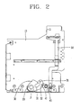
- FIGS. 1 to 3 One example of a draw in-out apparatus for an air circuit breaker in the related art which is capable of moving the main body to be electrically connected to or disconnected from the cradle in the air circuit breaker will be described with reference to FIGS. 1 to 3 .
- a reference numeral 10 designates a cradle, particularly, one of two side plates installed to be upright at both sides of the cradle.
- the draw in-out apparatus for the air circuit breaker in the related art includes a cam 30, a pinion gear 20 and a protruding portion B1.
- the cam 30 is installed at the cradle 10 so as to be supported and rotatable centering on a pivot P.
- the cam 30 is provided with a cam slot portion 31 as a driving slot portion for fitting the protruding portion B1 thereinto and transferring a force that allows the protruding portion B1 to horizontally move.
- the pinion gear 20 is installed at the pivot P so as to be coaxial with the cam 30.
- the draw in-out apparatus for the air circuit breaker in the related art may further include a movable plate MP provided with rack gears R on an upper portion thereof as shown in FIG. 6 .
- the pinion gear 20 can be rotated by the movable plate MP moving back and forth with being meshed with the rack gears R of the movable plate MP.
- the protruding portion B1 is protruded directly from a side surface of the main body or protruded from a plate-shaped rail supporting the main body and movable back and forth together with the main body thus to transfer a driving force which allows the main body to be moved to a connected position, a disconnected position or a test position.
- unexplained reference numerals 32, 40 and 50 are not directly related to the draw in-out apparatus of the present invention. They serve to automatically connecting a power source terminal and a signal terminal on the cradle 10 and a power source terminal and a signal terminal on the main body to each other at the test position or the connected position, and automatically disconnecting them from each other at the disconnected position.
- a reference numeral 32 designates a driving force transfer protrusion protruded from one side of the cam 30, and a reference numeral 40 designates a lever installed at the cradle 10 so as to be rotatable to a position for receiving a rotational driving force by being connected to the driving force transfer protrusion 32 and to a position for being separated from the rotational driving force by being disconnected from the driving force transfer protrusion 32.
- a reference numeral 50 designates a rod connected to the lever 40 and guided by a guiding member (reference numeral not given) thus to be movable in a vertical direction.
- a reference numeral 41 designates a connection recess portion provided at the lever 40 and connected to the driving force transfer protrusion 32.
- the lever 40 connected to the driving force transfer protrusion 32 of the cam 30 is rotated in the clockwise direction, and accordingly the rod 50 is moved down, thereby connecting the power source terminal and the signal terminal (not shown) of the cradle and the power source terminal and the signal terminal of the main body to each other thus to be positioned at the test position.
- the protruding portion B1 is positioned at an inlet of the cam slot portion 31 of the cam 30 without contacting with the cam 30, the main body does not move. Accordingly, the electric terminal (not shown) of the main body and the corresponding electric terminal of the cradle 10 remain disconnected from each other in the same state shown in FIG. 1 .
- a reaction point RP of the reaction force generated when the electric terminal of the cradle 10 and the electric terminal of the main body are connected to each other is positioned at the middle of a height difference between two electric terminal positions TP1, TP2 of the cradle 10 with a two point chain line as shown in FIG. 3 .
- a distance d1 between the reaction point RP of the reaction force and the pivot P of the cam 30 is long, as the air circuit breaker has larger capacity and size, it becomes to be more difficult for the cam 30 to endure the reaction force.
- the present invention is directed to providing a draw in-out apparatus for an air circuit breaker which is capable of effectively enduring a load of the main body and a reaction force generated when moving to a connected position and of being applied to an air circuit breaker having large capacity and size.
- a draw in-out apparatus for an air circuit breaker in an air circuit breaker comprising a cradle electrically connected to an electrical load and an electrical power source, and a main body that is movable to a connected position for being electrically connected to the cradle, a test position at which the main body is electrically disconnected from the cradle but a control power source is connected and a signal input/output is implemented, and a disconnected position at which the main body is electrically disconnected from the cradle, the control power source is not supplied and the signal input/output is not implemented
- the draw in-out apparatus for an air circuit breaker comprising: a spindle provided with a thread portion and manually rotatable (pivotable) by being connected to a handle; a movable plate meshed with the thread portion of the spindle by a screw so as to be movable back and forth along the
- an air circuit breaker in accordance with the present invention includes a main body 20 and a cradle 10.
- a reference character S1 referring a front lower portion of the main body 20 designates a handle connection portion of a spindle S, which is shown in FIG. 6 in detail.
- the main body 20 includes a switching mechanism (not shown), contactors, an arc extinguishing mechanism, an electric terminal (refer to a reference character T2 in FIGS. 10 and 11 ) for being electrically connected to the cradle 10.
- the main body 20 is movable to a connected position for being electrically connected to the cradle 10, a test position at which the main body 20 is electrically disconnected from the cradle 10 but a control power source (i.e., an electrical power source for a control unit) is connected and a signal input/output can be implemented, and a disconnected position at which the main body 20 is electrically disconnected from the cradle 10, the control power source is not supplied and the signal input/output is not implemented.
- a control power source i.e., an electrical power source for a control unit
- the cradle 10 serves as an enclosure supporting the main body 20 and as a means for electrically connecting the main body 20 and the external electrical circuit (in other words the external electrical power source and the external electrical load) to each other.
- the cradle 10 includes an external terminal (refer to a left portion of T1 in FIGS. 10 and 11 ) outwardly protruded to be electrically connected to the external power source and load and an internal terminal (refer to a right portion of T1 in FIGS. 10 and 11 ) to be connected to the electric terminal of the main body 20.
- FIGS. 5 to 7 a configuration of the draw in-out apparatus for the air circuit breaker in accordance with one embodiment of the present invention will be described.
- the draw in-out apparatus for the air circuit breaker in accordance with the present invention includes the spindle S, a movable plate MP and rack gears R as shown in FIG. 6 .
- the spindle S can be manually rotated by connecting the handle and provided with a thread portion.
- the movable plate MP is meshed with the thread portion of the spindle S by a screw and movable back and forth along the thread portion of the rotating spindle S.
- a reference character P1 in FIG. 6 designates a screw hole penetratingly formed along a middle portion of the movable plate MP in a length direction so as to be meshed with the thread portion of the spindle S by the screw.
- the rack gears R are installed on an upper surface of the movable plate MP and movable back and forth along with the moving plate MP moving back and forth.
- the rack gears may be entirely or partially formed on the upper surface of the movable plate MP.
- the draw in-out apparatus for the air circuit breaker in accordance with the present invention further includes pinion gears 300a, 300b, a cam 400, a pivot (refer to a reference character C in FIG. 5 ) and a driving protruding portion B1.
- the pinion gears 300a, 300b are installed to be meshable with the rack gears R and rotatable by the rack gears moving back and forth. As shown in FIG. 7 , the pinion gears 300a, 300b are installed on one common rotation shaft 200 and includes a first pinion gear 300a meshed with the rack gears R and a second pinion gear 300b meshed with teeth portions (refer to 400a in FIG. 5 ) of the cam 400.
- the cam 400 is meshed with the second pinion gear 300b and provided with the teeth portion having a radius larger than that of the second pinion gear 300b so as to amplify a torque transferred from the second pinion gear 300b.
- the cam 400 is rotatable by a rotational driving force transferred from the second pinion gear 300b.
- the cam 400 provides a driving force allowing the main body to be displaced.
- the cam 400 is provided with a cam slot portion 410 for enduring a load of the main body and a reaction force generated when the main body and the cradle are electrically connected to each other.
- the cam slot portion 410 of the cam 400 includes a plurality of cam surfaces 400b-1, 400b-3, 400b-5 in which each length of moment arms 11, 12, 13 from the pivot C of the cam 400 is gradually shortened from an opened inlet portion of the cam slot portion toward a closed inner end portion 400b so as to generate the torque for offsetting the load of the main body and the reaction force generated when the main body and the cradle are electrically connected to each other.
- each length of the moment arms 11, 12, 13 can be indicated as I1>I2>I3 since 11 is the longest, I2 is the middle and 13 is the shortest of the moment arms I1, I2, I3.
- the cam slot portion 410 of the cam 400 includes a first cam surface 400b-1 positioned at the opened inlet portion of the cam slot portion 410 and having the longest moment arm I1 from the pivot C of the cam 400. Further, the cam slot portion 410 of the cam 400 includes a second cam surface 400b-5 adjacent to the closed inner end portion 400b of the cam slot portion 410 and having the shortest moment arm I3 from the pivot C of the cam 400.
- the cam slot portion 410 of the cam 400 includes a third cam surface 400b-3 interconnecting between the first cam surface 400b-1 and the second cam surface 400b-5 and having the moment arm 13 shorter than the moment arm I1 of the first cam surface 400b-1 and longer than the moment arm 13 of the second cam surface 400b-5.
- an angle between the second cam surface 400b-5 and the third cam surface 400b-3 is substantially 0°or 180°.
- protrudingly extended from the main body or the a means for supporting the main body with moving together with the main body receives a pushing force from the second cam surface 400b-5 firstly and then from the third cam surface 400b-3 or the driving protruding portion B1 receives the pushing force from the third cam surface 400b-3 firstly and then from the second cam surface 400b-5, it is hardly accelerated. Rather, when receiving the pushing force from the third cam surface 400b-3 firstly and then from the second cam surface 400b-5, the driving protruding portion (refer to B1 in FIG. 7 ) is decelerated. That's because a radius of curvature of the third cam surface 400b-3 is larger than that of the second cam surface 400b-5.
- an angle between the first cam surface 400b-1 and the third cam surface 400b-3 is approximately 120°.
- the driving protruding portion (refer to B1 in FIG. 7 ) is accelerated when receiving the pushing force from the first cam surface 400b-1 firstly and then from the third cam surface 400b-3 or the driving protruding portion B1 receives the pushing force from the third cam surface 400b-3 firstly and then from the first cam surface 400b-1.
- the pivot C is disposed on the cradle at a position adjacent to the middle of a height between the electric terminals TP1, TP2 of the cradle, thus to rotatably support the cam. More particularly, as shown in FIG. 7 , a reaction point RP is applied to the middle of the height between the electric terminals TP1, TP2 of the cradle and indicated as a virtual line, i.e., a two point chain line.
- the reaction point RP of the reaction force also serves as a center point to which the load of the main body is applied.
- the pivot C is distant from the virtual line by a distance d2.
- a distance d1 of the related art pivot P of the cam 30 spaced from the two point chain line indicating the reaction point RP of the reaction force as the middle position between the electric terminals TP1, TP2 of the cradle shown in FIG. 3 is much shorter than the distance d2 of the pivot C in the draw in-out apparatus of the present invention spaced from the two point chain line indicating the reaction point RP of the reaction force. This can be represented as a formula d1>d2.
- the position of the pivot C of the cam 400 in the draw in-out apparatus of the present invention is more adjacent to the reaction point RP of the reaction force and the center point of the load of the main body, comparing with the related art, it is capable of effectively enduring the load of the main body and the reaction force generated when the electric terminal of the main body and the electric terminal of the cradle are connected to each other, accordingly it is capable of effectively allowing the air circuit breaker to have a high capacity and a large size.
- the driving protruding portion B1 is protrudingly extended from the main body or from the means supporting the main body with moving together with the main body, for example, a plate-shaped rail member (not shown) attached to both side surfaces of the main body.
- the driving protruding portion B1 is connected to the cam 400, more particularly, fitted into the cam slot portion 410 of the cam 400, thus to transfer the driving force from the rotating cam 400 to the main body so as to move the main body.
- an unexplained reference numeral 100 designates both side plates fixedly installed at both side surfaces of the cradle 10.
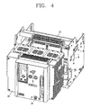
- the air circuit breaker in accordance with the present invention includes the cradle 10 and the main body 20 as shown in FIG. 4 , in addition to the configuration of the draw in-out apparatus in accordance with the present invention.
- the configuration of the draw in-out apparatus in accordance with the present invention is described above, thus the description will be omitted.
- the cradle 10 can be electrically connected to the load or power source of the circuit. And, the cradle 10 movably supports the main body 20.
- the electric terminal of the cradle 10 is indicated as a reference character T1 in FIGS. 10 to 11 . As shown in FIGS. 10 to 11 , the electric terminal is configured to include right and left electric connection terminals, and a left connection terminal therebetween is electrically connected to the load or power source of the circuit.
- the main body 20 is movable to a connected position for being electrically connected to the cradle 10 and a disconnected position for being electrically disconnected from the cradle 10. Even though it is not shown in FIG. 4 , the main body 20 is provided with a portion indicated as a reference character T2 as an electric terminal as shown in FIGS. 10 and 11 for being electrically connected to or disconnected from the cradle 10.
- the side plate 100 of the cradle is provided with an upper guiding rail UG and a lower guiding rail LR for guiding a horizontal movement of the main body 20.
- a plurality of guiding roller LR1 are rotatably installed at the lower guiding rail LR.
- FIG. 7 is a side view showing one side plate of the cradle without the main body, which shows a configuration of the draw in-out apparatus for the air circuit breaker and a state of the draw in-out apparatus at the disconnected position.
- FIG. 8 is state view showing the draw in-out apparatus for the air circuit breaker at the test position in accordance with the present invention.
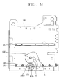
- FIG. 9 is a state view showing the draw in-out apparatus for the air circuit breaker at the connected position in accordance with the present invention.
- the air circuit breaker in accordance with the present invention, when the handle (not shown) is inserted into the handle connection hole S1 provided at the middle portion of the front manipulation panel (refer to FP in FIG. 6 ) in the length direction and then the spindle S is rotated in the clockwise direction, the movable plate MP shown in FIG. 6 is moved to a front side of the air circuit breaker, that is toward the front manipulation panel FP in FIG. 6 (rightward in FIG. 7 ) along the a thread portion of the spindle S.
- the rack gears R installed on the movable plate MP are meshed with the first pinion gear 300a thus to rotate the first pinion gear 300a in the counter-clockwise direction. Accordingly, the rotation shaft 200 is rotated in the counter-clockwise direction, and then the second pinion gear 300b coaxially connected to the rotation shaft 200 is also rotated in the counter-clockwise direction.
- the cam 400 having the teeth portion (refer to 400a in FIG. 5 ) meshed with the second pinion gear 300b is rotated in the clockwise direction from the state shown in FIG. 7 and then positioned as shown in FIG. 8 . Since the radius of the teeth portion of the cam 400 is greater than those of the pinion gears 300a, 300b, the cam 400 generates a torque amplified more than the torque of the second pinion gear 300b.
- the protruding portion B1 protruded from the main body or the supporting member movable with the main body with supporting it is positioned at the inlet of the slot portion 410 of the cam 400.
- a driving force transferring mechanism (not shown) connected so as to be interworked with the cam 400
- connectors respectively provided at the cradle 10 and the main body 20 for the power source and the signal input/output for a control unit (not shown) of the air circuit breaker are connected so as to be interworked with the rotating cam 400.
- the power source and the signal input/output can be implemented through the connectors. Accordingly, it is capable of testing whether or not the air circuit breaker is normally operated.
- the first pinion gear 300a meshed with the rack gears R installed on the movable plate MP at the test position is further rotated in the counter-clockwise direction. Accordingly, the rotation shaft 200 is further rotated in the counter-clockwise direction, and the second pinion gear 30b coaxially connected to the rotation shaft 200 is also further rotated in the counter-clockwise direction.
- the cam 400 having the teeth portion meshed with the second pinion gear 300b is further rotated in the clockwise direction from the state shown in FIG. 6 .
- the cam 400 since the radius of the teeth portion of the cam 400 is greater than those of the pinion gears 300a, 300b, the cam 400 generates the torque amplified more than the torque of the second pinion gear 300b.
- the cam 400 can provide a driving force allowing the main body having large capacity and size to be easily moved in the horizontal direction.
- the protruding portion B1 positioned at the inlet of the slot portion 410 of the cam 400 at the test position is pressed by the slot portion 410 due to the rotation of the cam 400 in the clockwise direction and then horizontally moved along a cam profile of the slot portion 410 thus to be positioned at a rear side of the cradle, i.e., a left side on the drawing, as shown in FIG. 9 .
- a rear side of the cradle i.e., a left side on the drawing
- the main body pressed by the protruding portion B1 is smoothly and rapidly moved in the horizontal direction toward the connected position by contacting with the first cam surface 400b-1 and the third cam surface 400b-3 extended from the first cam surface 400b-1 by an angle larger than 90°and smaller than 180°, for example, 120° through an inflection point 400b-2 and having a pre-determined radius of curvature, by the cam 400 rotating in the clockwise direction.
- the movement of the main body to the connected position at which the electric terminal T2 of the main body and the electric terminal T1 of the cradle are electrically and mechanically connected to each other is completed, as shown in FIG. 10 .
- the protruding portion B1 comes in contact with the second cam surface 400b-5 having an angle difference of 0°or 180°from the third cam surface 400b-3, that is, comes in contact with an extended surface nearly without an angle variation, accordingly, the angular acceleration and a moment of inertia according to the rotation cam 400 are decreased.
- the electric terminal T2 of the main body is electrically and mechanically connected to the corresponding electric terminal T1.
- connectors of cradle and the main body remain connected to each other mechanically and electrically. Accordingly, the circuit between the load and the power source comes to be in the electrically connected state, and the supply of power source and the signal input/output for the control unit of the air circuit breaker can be implemented.
- the rack gears R installed on the movable plate MP moving back are also moved backwardly, accordingly the first pinion gear 300a meshed with the rack gears R is rotated in the clockwise direction. Accordingly, the rotation shaft 200 is rotated in the clockwise direction and the second pinion gear 300b coaxially connected to the rotation shaft 200 is also rotated in the clockwise direction.
- the cam 400 having the teeth portion meshed with the second pinion gear 300b is rotated in the counter-clockwise direction from the state shown in FIG. 9 to be in the state shown in FIG. 8 .
- the cam 400 since the radius of the teeth portion of the cam 400 is greater than those of the pinion gears 300a, 300b, the cam 400 generates the torque amplified more than the torque of the second pinion gear 300b.
- the cam 400 can provide the driving force allowing the main body having the large capacity and size to be easily moved in the horizontal direction.
- the protruding portion B1 positioned at the second cam surface 400b-5 of the slot portion 410 of the cam 400 at the connected position is pressed by the slot portion 410 due to the rotation of the cam 400 in the counter-clockwise direction thus to be moved to the front side of the cradle in the horizontal direction, i.e., rightward on the drawing, along the cam profile of the slot portion 410 as shown in FIG. 8 .
- the main body is also moved toward the front side of the cradle by the moved distance of the protruding portion B1 in the horizontal direction.
- the electric terminal T2 of the main body and the electric terminal T1 of the cradle are mechanically and electrically disconnected from each other, as shown in FIG. 11 .
- the connectors of the main body and the cradle remain connected to each other and the load and power source on the circuit are electrically disconnected. Accordingly, the power source is supplied to the control unit of the air circuit breaker and the input/output for the control unit can be implemented.
- the rack gears R on the movable plate MP are also moved in the direction to be further distant from the front manipulation panel FP (leftward in FIG. 8 ), and the first pinion gear 300a meshed with the rack gears R is further rotated from the test position in the clockwise direction on the drawing. Accordingly, the rotation shaft 200 is further rotated in the clockwise direction and the second pinion gear 300b coaxially connected to the rotation shaft 200 is also further rotated in the clockwise direction.
- the cam 400 having the teeth portions meshed with the second pinion gear 300b is rotated in the counter-clockwise direction from the state shown in FIG. 8 .
- the protruding portion B1 is separated from the slot portion 410 of the cam 400 thus to be in the state shown in FIG. 7 .
- the pivot of the cam is positioned to be adjacent to the reaction point of the reaction force.
- the radius of the teeth portion of the cam is much larger than those of the pinion gears, accordingly it is capable of amplifying the rotational driving force.
- the cam transfers the driving force to the main body through the cam slot portion having the plurality of cam surfaces from the cam surface having the longest moment arm to the smallest moment arm from the pivot. Accordingly, the draw in-out apparatus for the air circuit breaker is capable of effectively enduring the load of the main body and the reaction force generated when moving to the connected position, and of being applied to an air circuit breaker having large capacity and size.
Landscapes
- Engineering & Computer Science (AREA)
- Power Engineering (AREA)
- Trip Switchboards (AREA)
- Driving Mechanisms And Operating Circuits Of Arc-Extinguishing High-Tension Switches (AREA)
- Breakers (AREA)
- Transmission Devices (AREA)
Applications Claiming Priority (1)
| Application Number | Priority Date | Filing Date | Title |
|---|---|---|---|
| KR1020070070274A KR100876409B1 (ko) | 2007-07-12 | 2007-07-12 | 인출형 차단기의 크레들 인입출 구조 |
Publications (3)
| Publication Number | Publication Date |
|---|---|
| EP2015413A2 true EP2015413A2 (fr) | 2009-01-14 |
| EP2015413A3 EP2015413A3 (fr) | 2010-08-18 |
| EP2015413B1 EP2015413B1 (fr) | 2016-08-31 |
Family
ID=39989897
Family Applications (1)
| Application Number | Title | Priority Date | Filing Date |
|---|---|---|---|
| EP08011915.9A Active EP2015413B1 (fr) | 2007-07-12 | 2008-07-02 | Appareil d'entrée/sortie pour disjoncteur à air |
Country Status (8)
| Country | Link |
|---|---|
| US (1) | US20090015990A1 (fr) |
| EP (1) | EP2015413B1 (fr) |
| JP (1) | JP4768782B2 (fr) |
| KR (1) | KR100876409B1 (fr) |
| CN (1) | CN101354986A (fr) |
| ES (1) | ES2604759T3 (fr) |
| MY (1) | MY143258A (fr) |
| RU (1) | RU2370870C1 (fr) |
Cited By (4)
| Publication number | Priority date | Publication date | Assignee | Title |
|---|---|---|---|---|
| CN102983523A (zh) * | 2012-12-18 | 2013-03-20 | 天津市百利电气有限公司 | 防止本体倾斜移动的抽屉式断路器 |
| USD954658S1 (en) * | 2020-04-27 | 2022-06-14 | Ls Electric Co., Ltd. | Air circuit breaker |
| WO2022126335A1 (fr) | 2020-12-14 | 2022-06-23 | Abb S.P.A. | Mécanisme de réglage pour disjoncteur et disjoncteur correspondant |
| USD959388S1 (en) * | 2020-01-15 | 2022-08-02 | Siemens Aktiengesellschaft | Switching device |
Families Citing this family (20)
| Publication number | Priority date | Publication date | Assignee | Title |
|---|---|---|---|---|
| KR100860530B1 (ko) * | 2007-07-12 | 2008-09-26 | 엘에스산전 주식회사 | 인출형 차단기 |
| KR100996791B1 (ko) * | 2008-04-10 | 2010-11-25 | 엘에스산전 주식회사 | 진공차단기의 주회로 단자 어셈블리 |
| US7821775B2 (en) * | 2008-04-15 | 2010-10-26 | General Electric Company | Racking mechanism for a circuit breaker |
| KR101026314B1 (ko) | 2008-12-31 | 2011-03-31 | 엘에스산전 주식회사 | 차단기의 위치검출장치 |
| KR200458099Y1 (ko) * | 2009-03-11 | 2012-01-18 | 엘에스산전 주식회사 | 진공 차단기의 인/입출 위치표시장치 |
| KR101158604B1 (ko) * | 2009-05-21 | 2012-06-22 | 엘에스산전 주식회사 | 진공차단기의 인입출 장치 |
| KR101031965B1 (ko) * | 2009-06-25 | 2011-04-29 | 엘에스산전 주식회사 | 회로차단기의 인입출 방지장치 |
| US8143608B2 (en) * | 2009-09-10 | 2012-03-27 | Avago Technologies Ecbu Ip (Singapore) Pte. Ltd. | Package-on-package (POP) optical proximity sensor |
| US8264809B2 (en) * | 2010-09-15 | 2012-09-11 | General Electric Company | System and apparatus for circuit protection within an equipment enclosure |
| RU2492562C1 (ru) * | 2012-03-23 | 2013-09-10 | Общество с ограниченной ответственностью "Нобель Трейд" ("ООО "Нобель Трейд") | Выкатной элемент шкафа комплектного распределительного устройства |
| US9350144B2 (en) | 2013-01-31 | 2016-05-24 | American Mine Research, Inc. | Removable contactor drawer |
| EP2966739A1 (fr) * | 2014-07-11 | 2016-01-13 | ABB Technology AG | Mécanisme d'insertion-extraction |
| US9336977B1 (en) | 2015-04-03 | 2016-05-10 | Eaton Corporation | Electrical switching apparatus and secondary disconnect assembly with terminal retention and correction features therefor |
| US9570261B2 (en) | 2015-04-03 | 2017-02-14 | Eaton Corporation | Electrical switching apparatus and secondary disconnect assembly with contact alignment features therefor |
| US9396889B1 (en) | 2015-04-03 | 2016-07-19 | Eaton Corporation | Electrical switching apparatus and secondary disconnect assembly with cradle assembly alignment and positioning features therefor |
| US9576762B2 (en) | 2015-04-03 | 2017-02-21 | Eaton Corporation | Electrical switching apparatus and secondary disconnect assembly with error-proofing features therefor |
| US9912128B2 (en) * | 2016-03-11 | 2018-03-06 | 9088-5625 Quebec Inc. | Circuit breaker positioning system and method for connection and disconnection thereof |
| CN106710911B (zh) * | 2016-12-13 | 2018-09-07 | 东莞同济大学研究院 | 一种抽屉式自动转换开关 |
| CN107732698B (zh) * | 2017-04-05 | 2019-04-09 | 胜利油田恒源电气有限责任公司 | 一种电力抽屉柜设备 |
| CN108198738B (zh) * | 2018-03-21 | 2024-02-02 | 常熟开关制造有限公司(原常熟开关厂) | 一种抽屉式断路器 |
Family Cites Families (17)
| Publication number | Priority date | Publication date | Assignee | Title |
|---|---|---|---|---|
| US2776346A (en) * | 1953-12-31 | 1957-01-01 | Gen Electric | Drawout mechanism for metal enclosed electric switchgear |
| SU420034A1 (ru) * | 1971-12-21 | 1974-03-15 | А. И. Замелан , Ю. В. Фещенко | Автоматический выключатель |
| US3918315A (en) * | 1974-07-22 | 1975-11-11 | William S Rouverol | High capacity gearing |
| US4139748A (en) * | 1977-01-05 | 1979-02-13 | Westinghouse Electric Corp. | Secondary contacts for drawout switchgear |
| EP0236179B1 (fr) * | 1986-02-10 | 1990-11-28 | Merlin Gerin | Mécanisme d'embrochage et de débrochage d'un disjoncteur électrique avec circuits principaux et auxiliaires |
| JPH08154315A (ja) * | 1994-11-29 | 1996-06-11 | Toshiba Corp | 電気機器の引出ユニット |
| US6005208A (en) * | 1998-03-03 | 1999-12-21 | General Electric Company | Industrial draw-out circuit breaker electrical connection indication |
| FR2777696B1 (fr) * | 1998-04-17 | 2000-05-26 | Schneider Electric Ind Sa | Dispositif de commande de la decharge et du debrayage d'un accumulateur d'energie lors de l'extraction d'un disjoncteur debrochable |
| FR2782579B1 (fr) * | 1998-08-24 | 2000-10-06 | Schneider Electric Ind Sa | Appareillage electrique de coupure comportant un disjoncteur embrochable et un dispositif indiquant l'etat du disjoncteur |
| FR2783366B1 (fr) * | 1998-09-11 | 2000-11-24 | Schneider Electric Ind Sa | Appareillage electrique de coupure comportant un disjoncteur debrochable et des indicateurs de la position du disjoncteur dans son chassis |
| CN2550940Y (zh) * | 2002-05-23 | 2003-05-14 | 常熟开关厂 | 断路器的传动装置 |
| US20080122563A1 (en) * | 2006-08-28 | 2008-05-29 | Ls Industrial Systems Co., Ltd. | Instantaneous trip mechanism for mould cased circuit breaker |
| KR100817118B1 (ko) * | 2006-10-17 | 2008-03-27 | 엘에스산전 주식회사 | 기중차단기의 가동접촉자 |
| KR100771922B1 (ko) * | 2006-10-17 | 2007-11-01 | 엘에스산전 주식회사 | 기중 차단기 |
| KR100771918B1 (ko) * | 2006-10-17 | 2007-11-01 | 엘에스산전 주식회사 | 기중차단기의 개폐기구 |
| KR100789448B1 (ko) * | 2006-12-29 | 2007-12-28 | 엘에스산전 주식회사 | 배선용 차단기용 단자 모듈 조립체 및 상기 단자 모듈조립체를 장착한 배선용 차단기 |
| KR100860530B1 (ko) * | 2007-07-12 | 2008-09-26 | 엘에스산전 주식회사 | 인출형 차단기 |
-
2007
- 2007-07-12 KR KR1020070070274A patent/KR100876409B1/ko active Active
-
2008
- 2008-07-01 US US12/165,789 patent/US20090015990A1/en not_active Abandoned
- 2008-07-02 ES ES08011915.9T patent/ES2604759T3/es active Active
- 2008-07-02 EP EP08011915.9A patent/EP2015413B1/fr active Active
- 2008-07-08 MY MYPI20082526A patent/MY143258A/en unknown
- 2008-07-11 RU RU2008128385/09A patent/RU2370870C1/ru active
- 2008-07-11 CN CNA2008101335242A patent/CN101354986A/zh active Pending
- 2008-07-11 JP JP2008181276A patent/JP4768782B2/ja active Active
Cited By (7)
| Publication number | Priority date | Publication date | Assignee | Title |
|---|---|---|---|---|
| CN102983523A (zh) * | 2012-12-18 | 2013-03-20 | 天津市百利电气有限公司 | 防止本体倾斜移动的抽屉式断路器 |
| CN102983523B (zh) * | 2012-12-18 | 2016-04-13 | 天津市百利电气有限公司 | 防止本体倾斜移动的抽屉式断路器 |
| USD959388S1 (en) * | 2020-01-15 | 2022-08-02 | Siemens Aktiengesellschaft | Switching device |
| USD954658S1 (en) * | 2020-04-27 | 2022-06-14 | Ls Electric Co., Ltd. | Air circuit breaker |
| WO2022126335A1 (fr) | 2020-12-14 | 2022-06-23 | Abb S.P.A. | Mécanisme de réglage pour disjoncteur et disjoncteur correspondant |
| EP4260355A4 (fr) * | 2020-12-14 | 2024-09-04 | ABB S.p.A. | Mécanisme de réglage pour disjoncteur et disjoncteur correspondant |
| US12374516B2 (en) | 2020-12-14 | 2025-07-29 | Abb S.P.A. | Adjustment mechanism for circuit breaker and corresponding circuit breaker |
Also Published As
| Publication number | Publication date |
|---|---|
| EP2015413B1 (fr) | 2016-08-31 |
| JP4768782B2 (ja) | 2011-09-07 |
| EP2015413A3 (fr) | 2010-08-18 |
| RU2370870C1 (ru) | 2009-10-20 |
| US20090015990A1 (en) | 2009-01-15 |
| JP2009022160A (ja) | 2009-01-29 |
| KR100876409B1 (ko) | 2008-12-31 |
| MY143258A (en) | 2011-04-15 |
| ES2604759T3 (es) | 2017-03-09 |
| CN101354986A (zh) | 2009-01-28 |
Similar Documents
| Publication | Publication Date | Title |
|---|---|---|
| EP2015413B1 (fr) | Appareil d'entrée/sortie pour disjoncteur à air | |
| EP2015338B1 (fr) | Appareil de connexion automatique de terminal de commande pour disjoncteur à air de type extractible et circuit équipé de celui-ci | |
| US7397008B2 (en) | Switching mechanism for air circuit breaker | |
| EP2228812A1 (fr) | Dispositif amovible d'un circuit principal de disjoncteur à vide | |
| KR200462421Y1 (ko) | 진공 차단기의 거더와 트럭 어셈블리 | |
| CN103187201A (zh) | 具有互锁装置的真空断路器 | |
| JP7507084B2 (ja) | コネクタ装置 | |
| CN114496604A (zh) | 切换开关装置及自动转换开关电器 | |
| JP2018010810A (ja) | ソケット | |
| US10256052B2 (en) | Integrated interlock device of air circuit breaker and method of using the same | |
| CN210575787U (zh) | 一种断路器的操作系统和断路器 | |
| CN217280469U (zh) | 切换开关装置及自动转换开关电器 | |
| KR101759603B1 (ko) | 인출형 기중차단기의 제어단자 접속장치 | |
| CN103811237B (zh) | 具有大容量的塑壳式断路器 | |
| CN219534315U (zh) | 转换机构及隔离开关 | |
| CN209963614U (zh) | 一种断路器接线端子锁定解锁机构 | |
| AU2024250574A1 (en) | Transmission mechanism, action mechanism, conversion mechanism, linkage mechanism, remote tripping mechanism, and isolating switch | |
| KR101075539B1 (ko) | 쓰리포지션 단로기 | |
| CN114420477B (zh) | 旋转机构、切换开关装置及自动转换开关电器 | |
| CN113327808B (zh) | 一种隔离开关的触头系统 | |
| EP4300536A1 (fr) | Mécanisme d'actionnement pour disjoncteur | |
| CN112802720B (zh) | 一种断路器的操作系统和断路器 | |
| CN118098873A (zh) | 一种真空断路器 | |
| JP2009011070A (ja) | インターロック装置 | |
| JP5332715B2 (ja) | 配電盤のシャッタ装置 |
Legal Events
| Date | Code | Title | Description |
|---|---|---|---|
| PUAI | Public reference made under article 153(3) epc to a published international application that has entered the european phase |
Free format text: ORIGINAL CODE: 0009012 |
|
| 17P | Request for examination filed |
Effective date: 20080702 |
|
| AK | Designated contracting states |
Kind code of ref document: A2 Designated state(s): AT BE BG CH CY CZ DE DK EE ES FI FR GB GR HR HU IE IS IT LI LT LU LV MC MT NL NO PL PT RO SE SI SK TR |
|
| AX | Request for extension of the european patent |
Extension state: AL BA MK RS |
|
| PUAL | Search report despatched |
Free format text: ORIGINAL CODE: 0009013 |
|
| AK | Designated contracting states |
Kind code of ref document: A3 Designated state(s): AT BE BG CH CY CZ DE DK EE ES FI FR GB GR HR HU IE IS IT LI LT LU LV MC MT NL NO PL PT RO SE SI SK TR |
|
| AX | Request for extension of the european patent |
Extension state: AL BA MK RS |
|
| RIC1 | Information provided on ipc code assigned before grant |
Ipc: H02B 11/133 20060101AFI20100713BHEP Ipc: H01H 71/08 20060101ALI20100713BHEP |
|
| AKX | Designation fees paid |
Designated state(s): DE ES FR GB IT |
|
| 17Q | First examination report despatched |
Effective date: 20140224 |
|
| GRAP | Despatch of communication of intention to grant a patent |
Free format text: ORIGINAL CODE: EPIDOSNIGR1 |
|
| RIC1 | Information provided on ipc code assigned before grant |
Ipc: H02B 11/127 20060101AFI20151112BHEP Ipc: H01H 71/08 20060101ALI20151112BHEP |
|
| INTG | Intention to grant announced |
Effective date: 20151202 |
|
| GRAS | Grant fee paid |
Free format text: ORIGINAL CODE: EPIDOSNIGR3 |
|
| GRAP | Despatch of communication of intention to grant a patent |
Free format text: ORIGINAL CODE: EPIDOSNIGR1 |
|
| INTG | Intention to grant announced |
Effective date: 20160506 |
|
| GRAA | (expected) grant |
Free format text: ORIGINAL CODE: 0009210 |
|
| AK | Designated contracting states |
Kind code of ref document: B1 Designated state(s): DE ES FR GB IT |
|
| REG | Reference to a national code |
Ref country code: GB Ref legal event code: FG4D |
|
| REG | Reference to a national code |
Ref country code: DE Ref legal event code: R096 Ref document number: 602008045952 Country of ref document: DE |
|
| REG | Reference to a national code |
Ref country code: ES Ref legal event code: FG2A Ref document number: 2604759 Country of ref document: ES Kind code of ref document: T3 Effective date: 20170309 |
|
| REG | Reference to a national code |
Ref country code: DE Ref legal event code: R097 Ref document number: 602008045952 Country of ref document: DE |
|
| REG | Reference to a national code |
Ref country code: FR Ref legal event code: PLFP Year of fee payment: 10 |
|
| PLBE | No opposition filed within time limit |
Free format text: ORIGINAL CODE: 0009261 |
|
| STAA | Information on the status of an ep patent application or granted ep patent |
Free format text: STATUS: NO OPPOSITION FILED WITHIN TIME LIMIT |
|
| 26N | No opposition filed |
Effective date: 20170601 |
|
| REG | Reference to a national code |
Ref country code: FR Ref legal event code: PLFP Year of fee payment: 11 |
|
| PGFP | Annual fee paid to national office [announced via postgrant information from national office to epo] |
Ref country code: GB Payment date: 20200608 Year of fee payment: 13 |
|
| GBPC | Gb: european patent ceased through non-payment of renewal fee |
Effective date: 20210702 |
|
| PG25 | Lapsed in a contracting state [announced via postgrant information from national office to epo] |
Ref country code: GB Free format text: LAPSE BECAUSE OF NON-PAYMENT OF DUE FEES Effective date: 20210702 |
|
| P01 | Opt-out of the competence of the unified patent court (upc) registered |
Effective date: 20230625 |
|
| PGFP | Annual fee paid to national office [announced via postgrant information from national office to epo] |
Ref country code: FR Payment date: 20250611 Year of fee payment: 18 |
|
| PGFP | Annual fee paid to national office [announced via postgrant information from national office to epo] |
Ref country code: ES Payment date: 20250822 Year of fee payment: 18 |
|
| PGFP | Annual fee paid to national office [announced via postgrant information from national office to epo] |
Ref country code: DE Payment date: 20250609 Year of fee payment: 18 |
|
| PGFP | Annual fee paid to national office [announced via postgrant information from national office to epo] |
Ref country code: IT Payment date: 20250610 Year of fee payment: 18 |