EP2015416A1 - Outil pour dénuder les câbles électriques - Google Patents
Outil pour dénuder les câbles électriques Download PDFInfo
- Publication number
- EP2015416A1 EP2015416A1 EP08159969A EP08159969A EP2015416A1 EP 2015416 A1 EP2015416 A1 EP 2015416A1 EP 08159969 A EP08159969 A EP 08159969A EP 08159969 A EP08159969 A EP 08159969A EP 2015416 A1 EP2015416 A1 EP 2015416A1
- Authority
- EP
- European Patent Office
- Prior art keywords
- handle
- cable
- stripping tool
- sleeve
- tool according
- Prior art date
- Legal status (The legal status is an assumption and is not a legal conclusion. Google has not performed a legal analysis and makes no representation as to the accuracy of the status listed.)
- Withdrawn
Links
- 230000006835 compression Effects 0.000 claims description 4
- 238000007906 compression Methods 0.000 claims description 4
- 238000006073 displacement reaction Methods 0.000 claims description 4
- 230000002093 peripheral effect Effects 0.000 abstract 1
- 238000009413 insulation Methods 0.000 description 3
- 238000004519 manufacturing process Methods 0.000 description 3
- 230000005283 ground state Effects 0.000 description 2
- 238000012423 maintenance Methods 0.000 description 2
- 230000006978 adaptation Effects 0.000 description 1
- 230000015572 biosynthetic process Effects 0.000 description 1
- 239000004020 conductor Substances 0.000 description 1
- 238000013461 design Methods 0.000 description 1
- 238000011161 development Methods 0.000 description 1
- 230000018109 developmental process Effects 0.000 description 1
- 238000005755 formation reaction Methods 0.000 description 1
- 239000000463 material Substances 0.000 description 1
- 238000000034 method Methods 0.000 description 1
- 238000012545 processing Methods 0.000 description 1
Images

Classifications
-
- H—ELECTRICITY
- H02—GENERATION; CONVERSION OR DISTRIBUTION OF ELECTRIC POWER
- H02G—INSTALLATION OF ELECTRIC CABLES OR LINES, OR OF COMBINED OPTICAL AND ELECTRIC CABLES OR LINES
- H02G1/00—Methods or apparatus specially adapted for installing, maintaining, repairing or dismantling electric cables or lines
- H02G1/12—Methods or apparatus specially adapted for installing, maintaining, repairing or dismantling electric cables or lines for removing insulation or armouring from cables, e.g. from the end thereof
- H02G1/1202—Methods or apparatus specially adapted for installing, maintaining, repairing or dismantling electric cables or lines for removing insulation or armouring from cables, e.g. from the end thereof by cutting and withdrawing insulation
- H02G1/1204—Hand-held tools
- H02G1/1229—Hand-held tools the cutting element making a longitudinal, and a transverse or a helical cut
- H02G1/1231—Hand-held tools the cutting element making a longitudinal, and a transverse or a helical cut using a swivelling cutting element
Definitions
- the invention relates to a cable stripping tool.
- the cutting blade In order to facilitate stripping of cables of relatively large diameter or with thick and stiff Isolierummantelept, it is known to design the cutting blade so that it over the normal cutting position, in which a round cut can be performed by 90 ° to a second position can be twisted. This allows the execution of a longitudinal section starting from the circular section in the direction of the cable end or along a cable section ausklinkenden. Such a cut cable sheath can then be relatively easily removed. In some solutions, the cutting blade can still occupy a third position, which is arranged between the position for the round section and that for the longitudinal section. This third position is for performing a spiral cut. With a spiral cut, especially thick or tough insulating sheathing can be removed particularly well.
- the DE 696 17 740 T2 describes a stripping apparatus having a selector, a blade carrier supported by the selector and having a projecting cutting blade, a cable clip slidably mounted on the selector, and a cooperating stopper on the blade carrier and selector to form first, second, and second clamps to define a third cutting position.
- Selector and blade carrier can be rotated relative to each other. In the first cutting position, a round cut, in the second cutting position, a longitudinal section and in the third cutting position, a spiral cut can be performed.
- the stripper also has a spring means to apply to the blade carrier a bias in the direction of rotation relative to the selector, whereby the blade carrier is pressed in the direction of rotation in either the first or the third cutting position.
- a cable stripping tool that includes first and second parts that can rotate about an axis relative to one another.
- the first part carries a cutting blade near the axis.
- the second part carries a hook which can move axially and which is biased by a first spring means relative to the cutting blade towards an end position.
- the hook can be exchanged to adapt to different cable diameters.
- the first part is a cam disc not rotatably connected, which can be moved axially along the first part.
- the cam has engagement circumferences spaced about its periphery which cooperate with a cam follower carried by the second portion to adjust the cutting blade in corresponding positions relative to the second portion.
- a second spring means provides axial biasing of the cam plate such that the cam follower and the engagement formations are frictionally engaged.
- the object of the present invention is therefore to provide an improved Jardinabmantelwerkmaschine available which allows a simple way a change between different cutting positions, a desired cutting position should be preset and fixable in order to cut again in the selected cutting position, wherein the tool has a simple structure of as few components and should cause a low production cost.
- the Jardinabmantelwerkmaschine invention is characterized on the one hand by the fact that the handle by a second spring means against a hook-carrying, preferably concentric with the handle disposed sleeve is displaceable. Furthermore, it is characteristic that the handle has a groove extending in the circumferential direction with at least three transversely to the longitudinal extent of the groove introduced detents, in which a sleeve connected to the bolt is guided, which is in the ready state of the Jardinabmanteltechnikmaschines in engagement with one of the detents.
- the bolt By moving the handle in the direction of the hook and turning the handle, the bolt can be brought from an initially assumed detent position to a new detent position.
- the different notches are also connected to different positions of the cutting blade, to allow in this way the optional execution of a longitudinal section, a round section or a spiral cut.
- An advantage of the solution according to the invention is that a simple way of positioning the cutting blade can be made.
- the integrated adjustment functionality also requires only a very small manufacturing overhead. It is only a groove with corresponding notches to bring into the handle and to provide the sleeve with a bolt. Furthermore, a spring means is still required, which allows a displacement of the handle relative to the sleeve.
- the bolt In work-ready ground state of the Abmantelwerkzeugs the bolt is locked in one of the detents, whereby the sleeve is secured against undesired rotation. An unintentional adjustment of the cutting direction can thus be safely avoided.
- the hook consists of an upper part serving to receive a cable and a lower part accommodated by the sleeve.
- the upper part is releasably connected, for example via a screw or a spring bolt, with the lower part.
- wear of the upper part of this can be easily replaced.
- different upper parts can be mounted on the lower part, which differ in that they are adapted to different cable diameters or cross-sectional shapes. This adaptability is achieved in that the tops have different effective lengths for holding the cable. From the prior art, it is known to provide complete replacement hooks with different effective lengths to adapt the tool to the cable diameter.
- the upper part is provided with a profiling.
- This profiling is adapted to the profiling of the cable to be stripped. In this way, long-twisted form cables can be easily stripped, since the profiling of the upper part of the tool can follow the course of the profiling of the cable in the longitudinal section.
- the handle is connected via a sliding toothing with the inner body.
- sliding teeth can be made a positive and non-positive connection between the handle and inner body.
- a securing ring is arranged on the inner body, which limits the displacement of the handle by the second spring means. It has proven to be advantageous if the cutting blade is detachably connected to the inner body. When worn, the cutting blade can thus be easily replaced.
- the groove is hidden from the outside introduced into the handle or provided with a groove covering the cover.
- Such configured groove is not accessible from the outside. It therefore can not pollute. In addition, there is also no danger that the operator may pinch in the groove during the stripping process.
- the handle has an indication of the set cutting position. This is for the At any time, operators can easily see in which cutting position the tool is currently located.
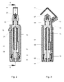
- the Jardinabmantelwerkmaschine invention comprises a sleeve-shaped handle 01 and disposed within the handle 01 and with this via a sliding toothing 03 positively and non-positively connected inner body 05.
- a cutting blade 07 is arranged at the protruding from the handle 01 end of the inner body 05.
- a sleeve 09 is arranged concentrically.
- Handle 01 and sleeve 09 are rotatable relative to each other about an axis.
- With the sleeve 09 a hook 11, 13 is connected.
- the hook 11, 13 is axially movable relative to the handle and biased by a first spring means 15 relative to the cutting blade 07 towards an end position.
- the first spring means 15 is preferably designed as a compression spring.
- the hook has a concave side 11 which faces the cutting blade 07 and serves to receive the cable to be stripped, and a substantially axially aligned shaft 13 which is received by the sleeve 09.
- the hook consists of an upper part 11 (corresponds here to the concave side) and a lower part 13 (corresponds to the shaft here), which are detachably connected to one another via a screw 17 or a comparable connecting means.
- the upper part 11 can also engage in a corresponding groove of the lower part 13.
- different tops 11 can be attached, which are adapted to different cable diameters. Characterized in that the hook 11, 13 is made in two parts, the tool can thus be easily adapted to cables of different diameters.
- only an exchange of the upper part 11 is required. Replacement of the upper part 11 may also be necessary in case of wear of the same.
- the handle 01 is displaceable by a second spring means 19 with respect to the sleeve 11 carrying the hook 11, 13.
- the second spring means 19 is preferably designed as a compression spring.
- a groove 21 is introduced, which has at least three notches.
- the groove 21 may be concealed or open. In this groove 21 a connected to the sleeve 09 pin 23 is guided.
- each of the detents is connected to a specific position of the cutting blade 07 relative to the hook 11, 13. In a first detent position, the cutting blade 07 is positioned so that a round cut can be performed. In a second detent position, the cutting blade 07 is aligned to perform a longitudinal section. In a third detent position, the cutting blade 07 is positioned so that a spiral cut can be performed.
- the pin 23 By moving the handle 01 in the direction of hooks 11, 13 and turning the handle, the pin 23 can be brought from its originally assumed detent position into a new detent position. This is also accompanied by a corresponding repositioning of the cutting blade 07. A once taken detent position is maintained until the handle 01 is pushed again in the direction of hooks 11, 13 and rotated to the desired position and locked. Characterized in that the bolt 23 is locked in the ground state ready for work of the tool in one of the detents, the sleeve 09 is secured against undesired rotation. An unintentional adjustment of the cutting direction can thus be safely avoided. For setting and detecting the respective desired cutting position, it has proven to be expedient if the handle 01 is provided with a corresponding indicator 27 for the cutting position.
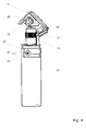
- Fig. 4 a modified embodiment of the Abmantelwerkmaschines is shown.
- the upper part 11 here has a profiling 29 which is adapted to an existing profiling of the cable to be stripped.
- a longitudinal section can easily be made, since the tool follows the profiling of the shaped cable 18 during a movement in the longitudinal direction of the shaped cable 18 through the profiling 12 of the upper part 11. Due to the locking of the bolt 23 in the catch for longitudinal section, it comes even in the processing of such profiled cable to a clean longitudinal section and not to a skewing of the cutting blade 07th
Landscapes
- Removal Of Insulation Or Armoring From Wires Or Cables (AREA)
Applications Claiming Priority (1)
| Application Number | Priority Date | Filing Date | Title |
|---|---|---|---|
| DE102007032399A DE102007032399B3 (de) | 2007-07-10 | 2007-07-10 | Kabelabmantelwerkzeug |
Publications (1)
| Publication Number | Publication Date |
|---|---|
| EP2015416A1 true EP2015416A1 (fr) | 2009-01-14 |
Family
ID=39678239
Family Applications (1)
| Application Number | Title | Priority Date | Filing Date |
|---|---|---|---|
| EP08159969A Withdrawn EP2015416A1 (fr) | 2007-07-10 | 2008-07-09 | Outil pour dénuder les câbles électriques |
Country Status (2)
| Country | Link |
|---|---|
| EP (1) | EP2015416A1 (fr) |
| DE (1) | DE102007032399B3 (fr) |
Cited By (10)
| Publication number | Priority date | Publication date | Assignee | Title |
|---|---|---|---|---|
| CN108847620A (zh) * | 2018-07-10 | 2018-11-20 | 苏州瑞得恩自动化设备科技有限公司 | 一种电动剥线装置用可拆卸套筒及加工工艺 |
| WO2020124081A1 (fr) | 2018-12-14 | 2020-06-18 | Ripley Tools, Llc | Outil à dénuder les câbles |
| CN111786321A (zh) * | 2020-07-03 | 2020-10-16 | 河南中烟工业有限责任公司 | 一种可调节电缆剥皮装置 |
| CN113013794A (zh) * | 2021-04-16 | 2021-06-22 | 珠海城市职业技术学院 | 一种自动化电缆剥皮装置及其装夹定位方法 |
| CN114094503A (zh) * | 2021-11-18 | 2022-02-25 | 广东电网有限责任公司 | 一种线缆剥皮装置及剥皮方法 |
| CN114899766A (zh) * | 2019-07-16 | 2022-08-12 | 铜陵博康机电有限公司 | 一种线束剥线用工作台的操作方法 |
| CN115173328A (zh) * | 2022-09-08 | 2022-10-11 | 安徽省景卓信息技术有限公司 | 一种外护套半导电层刮除用夹持装置 |
| CN115241810A (zh) * | 2022-09-23 | 2022-10-25 | 国网山东省电力公司高密市供电公司 | 一种配电箱电缆用剥皮装置及剥皮方法 |
| CN115333006A (zh) * | 2022-08-17 | 2022-11-11 | 国网河南省电力公司焦作供电公司 | 一种电缆头去皮装置及使用方法 |
| EP4191810A1 (fr) * | 2021-12-01 | 2023-06-07 | Krampe Werkzeuge GmbH & Co. KG | Outil de dénudage de câbles |
Families Citing this family (6)
| Publication number | Priority date | Publication date | Assignee | Title |
|---|---|---|---|---|
| FR2992109B3 (fr) * | 2012-06-14 | 2014-12-12 | Stanley Works Europe Gmbh | Outil a lame pliable d electricien pour denuder un conducteur electrique |
| FR2992110B3 (fr) | 2012-06-14 | 2014-12-12 | Stanley Works Europe Gmbh | Outil de denudage de cables electriques |
| DE102018115487A1 (de) | 2018-06-27 | 2020-01-02 | Weidmüller Interface GmbH & Co. KG | Werkzeug zum Abmanteln eines Kabels |
| CN113725785B (zh) * | 2021-08-31 | 2022-10-21 | 华核电气股份有限公司 | 一种配电柜连接线用加工设备 |
| WO2024002876A1 (fr) * | 2022-06-28 | 2024-01-04 | Weicon Gmbh & Co Kg | Couteau à dénuder pour câbles en nappe |
| CN116365430B (zh) * | 2023-03-29 | 2023-11-03 | 国网安徽省电力有限公司涡阳县供电公司 | 一种用于电缆的快速剥皮装置 |
Citations (5)
| Publication number | Priority date | Publication date | Assignee | Title |
|---|---|---|---|---|
| FR1294484A (fr) * | 1961-07-07 | 1962-05-26 | Appareil pour couper les gaines de conducteurs électriques | |
| FR2514960A1 (fr) * | 1980-08-29 | 1983-04-22 | Weidmueller C A Gmbh Co | Instrument pour denuder les cables electriques |
| US5829141A (en) * | 1996-09-30 | 1998-11-03 | Technical And Management Services Corporation | Device for cutting insulation |
| DE69617740T2 (de) | 1995-09-13 | 2002-07-18 | Barry Peter Liversidge | Abisoliervorrichtung |
| EP1322010A1 (fr) * | 2001-12-19 | 2003-06-25 | Pressmaster AB | Outil de dénudage d'un câble |
-
2007
- 2007-07-10 DE DE102007032399A patent/DE102007032399B3/de not_active Expired - Fee Related
-
2008
- 2008-07-09 EP EP08159969A patent/EP2015416A1/fr not_active Withdrawn
Patent Citations (6)
| Publication number | Priority date | Publication date | Assignee | Title |
|---|---|---|---|---|
| FR1294484A (fr) * | 1961-07-07 | 1962-05-26 | Appareil pour couper les gaines de conducteurs électriques | |
| FR2514960A1 (fr) * | 1980-08-29 | 1983-04-22 | Weidmueller C A Gmbh Co | Instrument pour denuder les cables electriques |
| DE69617740T2 (de) | 1995-09-13 | 2002-07-18 | Barry Peter Liversidge | Abisoliervorrichtung |
| US5829141A (en) * | 1996-09-30 | 1998-11-03 | Technical And Management Services Corporation | Device for cutting insulation |
| EP1322010A1 (fr) * | 2001-12-19 | 2003-06-25 | Pressmaster AB | Outil de dénudage d'un câble |
| EP1322010B1 (fr) | 2001-12-19 | 2007-02-14 | Pressmaster AB | Outil de dénudage d'un câble |
Cited By (17)
| Publication number | Priority date | Publication date | Assignee | Title |
|---|---|---|---|---|
| CN108847620A (zh) * | 2018-07-10 | 2018-11-20 | 苏州瑞得恩自动化设备科技有限公司 | 一种电动剥线装置用可拆卸套筒及加工工艺 |
| CN108847620B (zh) * | 2018-07-10 | 2023-11-21 | 苏州瑞得恩自动化设备科技有限公司 | 一种电动剥线装置用可拆卸套筒 |
| WO2020124081A1 (fr) | 2018-12-14 | 2020-06-18 | Ripley Tools, Llc | Outil à dénuder les câbles |
| US11435526B2 (en) | 2018-12-14 | 2022-09-06 | Ripley Tools, Llc | Cable stripping tool with offset roller system |
| EP3895268A4 (fr) * | 2018-12-14 | 2022-11-16 | Ripley Tools, LLC | Outil à dénuder les câbles |
| CN114899766B (zh) * | 2019-07-16 | 2023-12-26 | 铜陵博康机电有限公司 | 一种线束剥线用工作台的操作方法 |
| CN114899766A (zh) * | 2019-07-16 | 2022-08-12 | 铜陵博康机电有限公司 | 一种线束剥线用工作台的操作方法 |
| CN111786321A (zh) * | 2020-07-03 | 2020-10-16 | 河南中烟工业有限责任公司 | 一种可调节电缆剥皮装置 |
| CN113013794A (zh) * | 2021-04-16 | 2021-06-22 | 珠海城市职业技术学院 | 一种自动化电缆剥皮装置及其装夹定位方法 |
| CN113013794B (zh) * | 2021-04-16 | 2024-05-24 | 珠海城市职业技术学院 | 一种自动化电缆剥皮装置及其装夹定位方法 |
| CN114094503A (zh) * | 2021-11-18 | 2022-02-25 | 广东电网有限责任公司 | 一种线缆剥皮装置及剥皮方法 |
| EP4191810A1 (fr) * | 2021-12-01 | 2023-06-07 | Krampe Werkzeuge GmbH & Co. KG | Outil de dénudage de câbles |
| CN115333006A (zh) * | 2022-08-17 | 2022-11-11 | 国网河南省电力公司焦作供电公司 | 一种电缆头去皮装置及使用方法 |
| CN115173328A (zh) * | 2022-09-08 | 2022-10-11 | 安徽省景卓信息技术有限公司 | 一种外护套半导电层刮除用夹持装置 |
| CN115173328B (zh) * | 2022-09-08 | 2022-12-02 | 安徽省景卓信息技术有限公司 | 一种外护套半导电层刮除用夹持装置 |
| CN115241810A (zh) * | 2022-09-23 | 2022-10-25 | 国网山东省电力公司高密市供电公司 | 一种配电箱电缆用剥皮装置及剥皮方法 |
| CN115241810B (zh) * | 2022-09-23 | 2022-12-02 | 国网山东省电力公司高密市供电公司 | 一种配电箱电缆用剥皮装置及剥皮方法 |
Also Published As
| Publication number | Publication date |
|---|---|
| DE102007032399B3 (de) | 2008-09-11 |
Similar Documents
| Publication | Publication Date | Title |
|---|---|---|
| DE102007032399B3 (de) | Kabelabmantelwerkzeug | |
| DE69008411T2 (de) | Entmantelungsapparat für Koaxialkabel. | |
| EP1096628B1 (fr) | Méthode et dispositif pour dépouiller l'écran d'un câble | |
| EP2163358B1 (fr) | Poignée supplémentaire pour une machine-outil manuelle | |
| DE29901705U1 (de) | Mehrzweckwerkzeug | |
| DE69617740T2 (de) | Abisoliervorrichtung | |
| DE2744410A1 (de) | 4-backen-spannfutter fuer ein werkstueck | |
| EP2045045B1 (fr) | Machine-outil électrique manuelle | |
| EP1995024B1 (fr) | Appareil de travail manuel | |
| CH649020A5 (en) | Chuck for taps | |
| DE3136406C2 (fr) | ||
| EP1724893A1 (fr) | Outil pour dénuder un câble | |
| DE10259959A1 (de) | Kraftspannfutter und Keilstange dafür | |
| EP0459121A2 (fr) | Sabot de guidage pour machine portative | |
| EP0599090A1 (fr) | Outil manuel électrique, en particulier meuleuse d'angle | |
| DE2339778A1 (de) | Gewindeschneidvorrichtung | |
| DE2854121C2 (de) | An ein Maschinenteil ansetzbare Vorrichtung zum Ausstechen von Ringlippen dort in Bohrungen eingestemmter Lagerbüchsen | |
| DE4409160C1 (de) | Rohrabstechgerät für Kunststoffrohre | |
| DE102017101836B4 (de) | Vorrichtung zur Demontage von Ringdichtungen | |
| DE1425095B1 (de) | Vorrichtung zum Betaetigen eines Zugkabels | |
| DE19800734B4 (de) | Rohrschneidegerät | |
| EP0178458A2 (fr) | Enrouleur | |
| EP1258959A1 (fr) | Appareil réglable d'enlèvement de couches en forme de pince ou de serre-joints | |
| DE630494C (de) | Sicherheitsrasierapparat | |
| EP0249184B1 (fr) | Dispositif à fileter |
Legal Events
| Date | Code | Title | Description |
|---|---|---|---|
| PUAI | Public reference made under article 153(3) epc to a published international application that has entered the european phase |
Free format text: ORIGINAL CODE: 0009012 |
|
| AK | Designated contracting states |
Kind code of ref document: A1 Designated state(s): AT BE BG CH CY CZ DE DK EE ES FI FR GB GR HR HU IE IS IT LI LT LU LV MC MT NL NO PL PT RO SE SI SK TR |
|
| AX | Request for extension of the european patent |
Extension state: AL BA MK RS |
|
| AKX | Designation fees paid | ||
| STAA | Information on the status of an ep patent application or granted ep patent |
Free format text: STATUS: THE APPLICATION IS DEEMED TO BE WITHDRAWN |
|
| 18D | Application deemed to be withdrawn |
Effective date: 20090715 |
|
| REG | Reference to a national code |
Ref country code: DE Ref legal event code: 8566 |