EP2015442A2 - Dispositif destiné au fonctionnement d'une machine synchrone - Google Patents
Dispositif destiné au fonctionnement d'une machine synchrone Download PDFInfo
- Publication number
- EP2015442A2 EP2015442A2 EP08104360A EP08104360A EP2015442A2 EP 2015442 A2 EP2015442 A2 EP 2015442A2 EP 08104360 A EP08104360 A EP 08104360A EP 08104360 A EP08104360 A EP 08104360A EP 2015442 A2 EP2015442 A2 EP 2015442A2
- Authority
- EP
- European Patent Office
- Prior art keywords
- forming
- magnetic field
- current
- torque
- max
- Prior art date
- Legal status (The legal status is an assumption and is not a legal conclusion. Google has not performed a legal analysis and makes no representation as to the accuracy of the status listed.)
- Granted
Links
Images
Classifications
-
- H—ELECTRICITY
- H02—GENERATION; CONVERSION OR DISTRIBUTION OF ELECTRIC POWER
- H02P—CONTROL OR REGULATION OF ELECTRIC MOTORS, ELECTRIC GENERATORS OR DYNAMO-ELECTRIC CONVERTERS; CONTROLLING TRANSFORMERS, REACTORS OR CHOKE COILS
- H02P21/00—Arrangements or methods for the control of electric machines by vector control, e.g. by control of field orientation
- H02P21/0085—Arrangements or methods for the control of electric machines by vector control, e.g. by control of field orientation specially adapted for high speeds, e.g. above nominal speed
- H02P21/0089—Arrangements or methods for the control of electric machines by vector control, e.g. by control of field orientation specially adapted for high speeds, e.g. above nominal speed using field weakening
-
- H—ELECTRICITY
- H02—GENERATION; CONVERSION OR DISTRIBUTION OF ELECTRIC POWER
- H02P—CONTROL OR REGULATION OF ELECTRIC MOTORS, ELECTRIC GENERATORS OR DYNAMO-ELECTRIC CONVERTERS; CONTROLLING TRANSFORMERS, REACTORS OR CHOKE COILS
- H02P21/00—Arrangements or methods for the control of electric machines by vector control, e.g. by control of field orientation
- H02P21/22—Current control, e.g. using a current control loop
-
- H—ELECTRICITY
- H02—GENERATION; CONVERSION OR DISTRIBUTION OF ELECTRIC POWER
- H02P—CONTROL OR REGULATION OF ELECTRIC MOTORS, ELECTRIC GENERATORS OR DYNAMO-ELECTRIC CONVERTERS; CONTROLLING TRANSFORMERS, REACTORS OR CHOKE COILS
- H02P25/00—Arrangements or methods for the control of AC motors characterised by the kind of AC motor or by structural details
- H02P25/02—Arrangements or methods for the control of AC motors characterised by the kind of AC motor or by structural details characterised by the kind of motor
- H02P25/022—Synchronous motors
- H02P25/03—Synchronous motors with brushless excitation
Definitions
- the invention relates to a device for operating a synchronous machine with a stator, the three winding strands are assigned, and a rotor.
- Synchronous machines are used in the field of automotive technology, where they are used for example for steering systems of motor vehicles. Synchronous machines can be equipped with permanent magnets on the rotor. However, they can also be equipped with exciter windings in the rotor. Synchronous machines can be designed as salient-pole machines, in which the rotor has a pole wheel with pronounced poles. However, the synchronous machine can also be designed as a full-pole machine with a rotationally symmetrical rotor.
- a control for a synchronous machine with permanent magnets is known.
- the synchronous machine is controlled by means of a field-oriented current control.
- transformations of the currents and voltages are made into a coordinate system circulating with the rotor, a d, q-coordinate system.
- a field weakening of the magnetic field of the permanent magnets for speed increase above a nominal speed of the synchronous machine is mentioned on the basis of an impressed negative d-current, which can be assigned to a magnetic field-forming current of the rotor-rotating coordinate system.
- the object underlying the invention is to provide an apparatus for operating a synchronous machine which is simple and inexpensive.
- the invention is characterized by a device for operating a synchronous machine with a stator, the three winding strands are assigned, and a rotor, wherein the device is designed, a desired value of a magnetic field forming current in a rotating with the rotor of the synchronous coordinate system depending on a magnetic field forming Rohsollstromkomponente the rotor rotating coordinate system and a magnetic field forming current limit of the rotor rotating coordinate system to be determined in such a way that the target value of the magnetic field forming current is limited to the magnetic field forming current limit, the magnetic field forming current limit is below a typical for the synchronous machine in field weakening limit.
- the device is designed to reduce a torque-forming current limit of the rotor-rotating coordinate system in the region of the limitation of the nominal value of the magnetic field-forming current as a function of the magnetic field-forming Rohsollstromkomponente and the magnetic field-forming current limit amount.
- the nominal value of the magnetic field-forming current and the magnetic field-forming current limit are typically negative for a field-weakening operation of the synchronous machine. Due to the field weakening operation, the speed can be increased above the rated speed of the synchronous machine.
- the magnetic field-forming current limit is preferably set in such a way that it lies below the magnitude of a typical tilt limit for the synchronous machine in field weakening operation.
- the tilt limit is calculated from the general relationships of the permanent-magnet synchronous machine as a function of the nominal value of the magnetic field-forming current and thus also represents a stability limit for the field weakening operation. Due to the absolute reduction of the torque-forming current limit may be in the range of limiting the setpoint of the magnetic field-forming current particularly Advantageously, a typical for field weakening current limiting operation of an actuator for driving the synchronous machine are left and thus the power requirements are significantly improved. This ensures a particularly efficient and cost-effective operation of the synchronous machine.
- the device comprises a first controller, which is designed to determine a magnetic field-forming insectsrohsollstromkomponente dependent on a nominal value of a magnetic field forming voltage of the rotor-rotating coordinate system and a target value of a torque-forming voltage of the rotor-rotating coordinate system, depending on the magnetic field forming Rohsollstromkomponente is determined.
- the first controller is preferably designed in such a way that the magnetic field-forming insects is determined in the field weakening operation of the synchronous machine. This ensures particularly advantageous that the desired value of the magnetic field-forming current is only determined when a field weakening operation and thus an increase in the rotational speed of the synchronous machine on the rated speed is requested.
- the device comprises a filter unit, which is designed, depending on the Eisenrohsollstromkomponente, to determine the magnetic field forming Rohsollstromkomponente namely in the sense of low-pass filtering. Due to the low-pass filtering, the embrohsollstromkomponente can be particularly prefiltered.
- the device comprises a second limiting unit, which is designed to limit the desired value of the magnetic field-forming current to the magnetic field-forming current limit.
- the magnetic field-forming current limit is preferably designed in such a way that it is below the limit and thus under the stability limit is, so that a resulting from the control instability absolute increase of the magnetic field-forming current that would be typical if the limit is exceeded, is particularly reliably prevented and ensures a particularly efficient and cost-effective operation of the synchronous machine.
- the device comprises a second regulator, which is designed to determine a torque-forming auxiliary current component depending on the magnetic field-forming current limit and the magnetic field-forming Rohsollstromkomponente.
- the second controller determines the torque-forming auxiliary current component only if the primary field component forming the magnetic field exceeds the magnitude of the magnetic field-forming current limit. Otherwise, for example, a 0 can be specified for the torque-forming auxiliary current component.
- the second controller is designed as a PI controller.
- the PI controller ensures a particularly suitable determination of the torque-forming auxiliary current component.
- the second controller is designed as a functional unit which determines the torque-forming auxiliary current component in the sense of a tabular determination.
- the first controller is designed as a PI controller and comprises an input for the magnetic field-forming current limit and an input for the torque-forming auxiliary current component, wherein the PI controller is designed to keep depending on the magnetic field-forming current limit and the torque-forming auxiliary current component constant integral component of the PI controller constant.
- the nominal value of the magnetic field-forming current in the region of the magnetic field-forming current limit can keep the currently valid integral component constant in order to particularly suitably suppress a further unfavorable increase in the primary field component forming the magnetic field.
- the output of the PI controller in the sense of an anti-windup mechanism can be limited particularly suitable.
- the device comprises a first calculation unit, which is designed to determine a torque-forming raw current limit value depending on the desired value for driving the synchronous machine of the magnetic field-forming current and a predetermined maximum absolute current, which represents the absolute maximum current of an actuator.
- the torque-forming raw current limit value is determined in such a way that the actuator is not overloaded in terms of current and thus a particularly safe operation of the actuator for controlling the synchronous machine is ensured.
- the device comprises a second calculation unit which is designed to determine the torque-forming current limit as a function of the torque-forming raw current limit value and the torque-forming auxiliary current component.
- the second calculation unit may be designed such that the magnitude of the torque-forming current limit is reduced in such a way that the current-limiting operation typical of the field-weakening operation the actuator is left to control the synchronous machine and a particularly efficient and cost-effective operation of the synchronous machine is ensured.
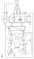
- a synchronous machine PMSM comprises a stator with three winding strands, each of which is arranged offset by 120 degrees.
- the synchronous machine PMSM further comprises a rotor, on which permanent magnets are arranged.
- the rotor with the permanent magnets can be rotationally symmetrical (fully charged rotor) or with pronounced poles (salient rotor).
- the stator comprises a three-phase symmetrical winding system.
- a position sensor POS is provided, by means of which an angle of the pole wheel relative to a predetermined reference mark on the stator can be detected.
- the measurement signal of the position sensor is fed to a block B1, which is a signal processing unit comprises and calculates from the measurement signal of the position sensor, the rotation angle ⁇ and also a rotational speed ⁇ s of the rotor relative to the stator.
- the position sensor may for example be designed as a resolver but it may also be, for example, an incremental position sensor comprising a Hall element or the like.
- a block B2 comprises a first limiting unit, which is designed to limit a predetermined raw setpoint value I q, REQ of a torque-forming current to a value of a torque-forming current limit I q, MAX in absolute terms.
- the torque-forming current limit I q, MAX is given by a field weakening unit B9, which is based on the block diagram of the FIG. 3 is explained in more detail.
- a block B3 which comprises a precontrol and the input side, the rotational speed ⁇ s of the rotor relative to the stator, the rotational angle ⁇ of the rotor relative to the stator and a resulting from the first limiting unit B2 setpoint I q, REF of the torque-generating current and a desired value I d, REF of a magnetic field-forming current are supplied and which is designed to determine pre-control values.
- the desired value I q, REF of the torque-forming current is preferably from another functional unit, for example the torque input of a speed controller in a variable-speed drive system or by a steering intervention in a steering system of a motor vehicle, in the sense of an adjustment a desired torque of the synchronous machine PMSM specified.
- a first connection point VK1 is provided, in which a difference is formed between the setpoint value Iq , REF of the torque-forming current and the one actual value Iq, ACT of the torque-forming current, this difference then being supplied as a control difference to a block B7 which has a q Controller.
- the q-controller can be designed for example as a PI controller. On the output side, the q-controller generates a corresponding controller value, which is then linked in a node VK2 to a corresponding pilot value of the pilot control of the block B3 to a setpoint value V q of a torque-forming voltage.
- a block B9 which comprises a field weakening unit B9 and the input side, the current supply voltage of an actuator S and the setpoint values V d , V q are fed to a magnetic field forming voltage and the torque-forming voltage.
- the output quantities of the block B9 are the nominal value I d, REF of the magnetic field-forming current and the torque-forming current limit I q, MAX , which limits the predetermined raw nominal value I q, REQ of the torque-generating current in the first limiting unit B2.
- field weakening unit B9 The more detailed embodiment of the field weakening unit B9 is described below with reference to the block diagram of FIG. 3 explained in more detail.
- a difference between the set point I d, REF of the magnetic field generating current and an actual value I d, ACT of the magnetic field generating current is determined as a control difference for a d-controller of a block B11.
- the d-controller for example, is also designed as a PI controller, but as well as the q-controller, it can also act as another the skilled person for this purpose be designed as suitable known controller.
- the d controller On the output side, the d controller generates a corresponding controller value, which is linked in a node VK4 with a corresponding pilot value of the pilot control B3 to the setpoint value V d of the magnetic field-forming voltage.
- a block B13 comprises a (d, q) / (r, s, t) transformation block which is adapted to perform an inverse Park and Clarke transformation and thus a corresponding transformation from the q, d coordinate system into corresponding r, s, t coordinates and thus serves to specify corresponding conductor voltages of the synchronous machine.
- the d, q-coordinate system is characterized by the fact that the corresponding transformed motor currents and voltages are time-invariant with a knowledge of the exact rotational angle ⁇ in a stationary operation of the synchronous machine.
- the actuator S has as input variables the output variables of the block B13.
- the actuator S preferably comprises a space vector pulse width modulator, which generates corresponding pulse width modulated actuating signals for a three-phase inverter likewise embodied in the actuator S.
- the three-phase inverter then supplies the synchronous machine with the desired phase voltages.
- a block B15 comprises a (r, s, t) / (d, q) transformation block which is designed to perform a Park and Clarke transformation and thus a corresponding transformation of r, s, t coordinates into the q, Performs d-coordinate system and thus sets the actual values I q, ACT , I d, ACT of the torque-forming and magnetic field forming current for the nodes VK1 and VK3.
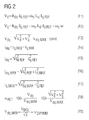
- An operation of the synchronous machine PMSM such as a Vollpol commentaryrmaschine or a salient-pole with Permanently excited rotor is determined by the two relations F1 and F2 in FIG. 2 described.
- the setpoint value V d in F1 represents a magnetic field-forming voltage component
- the setpoint value of the voltage V q in F 2 represents a torque-forming voltage component of the synchronous machine in the d, q coordinate system revolving around the rotor.
- An absolute voltage V dq is dependent on the setpoint value V d of the magnetic field forming voltage and the setpoint value V q of the torque-forming voltage and may be represented by a relationship F3 in FIG FIG. 2 to be discribed.
- the set values V d and V q of the magnetic field-forming and the torque-forming voltage are typically dependent on the predetermined setpoint I d, REF of the magnetic field generating current, the rotational speed ⁇ S of the rotor relative to the stator and the setpoint I q, REF of the torque-generating current.
- the relationships F1 and F2 in FIG. 2 a resistor R dq , which represents a strand resistance of the synchronous machine PMSM, and a concatenated magnetic flux ⁇ , which represents the concatenated rotor magnetic flux of the synchronous machine PMSM.
- the term ⁇ S ⁇ ⁇ in the relation F2 in FIG. 2 corresponds to the voltage induced in the stator winding.
- Lq and L d represent inductances in the q- and d-axis and are dependent on a design of the synchronous machine PMSM.
- An absolute current I dq which is representative of a current that the actuator S of the synchronous machine PMSM provides is typically determined by the relationship F4 in FIG. 2 solely by the setpoint I q, REF of the torque-generating current.
- the (d, q) / (r, s, t) transformation block is given a maximum absolute voltage V dq, MAX by the q and d regulators B7 and B11 and the precontrol B3. which according to the relationship F3 in FIG. 2 is described.
- the absolute current I dq is given by the relationship F5 in FIG. 2 described.
- the maximum absolute voltage V dq, MAX and a maximum absolute current I dq, MAX which varies according to the relation F6 in FIG. 2 are representative of the maximum current and voltage values that can be provided by the actuator S of the synchronous machine.
- the maximum absolute voltage V dq, MAX and the maximum absolute current I dq, MAX may or may not be exceeded.
- the field weakening unit B9 in FIG. 1 the field weakening operation specified.
- the field weakening operation is typically represented by the relationship F3 in FIG. 2 described in which the maximum absolute voltage V dq, MAX may not be exceeded, but is kept constant.
- the magnetic field of the permanent magnet of the rotor must be counteracted. This is achieved by using a negative setpoint I d, REF of the magnetic field generating current.
- I d, REF of the magnetic field generating current By using the negative setpoint value I d, REF of the magnetic field generating current, the increase of the induced voltage ⁇ S ⁇ ⁇ in the stator in F 2 in FIG FIG.
- the negative setpoint value I d, REF of the magnetic field generating current is predetermined by the field weakening unit B9 and counteracts the magnetic field of the permanent-magnet rotor of the synchronous machine PMSM.
- the setpoint I q, REF of the torque-generating current and the setpoint I d, REF of the magnetic field-forming current now form the absolute current I dq according to a relationship F5 in FIG FIG. 2 ,
- the setpoint I d, REF of the magnetic field-forming current results from a modulation index m ACT and thus the setpoint values V q and V d associated with the modulation index m ACT of the torque-forming voltage and the magnetic field-forming voltage.
- the modulation index m ACT is represented by a relation F8 in FIG FIG. 2 wherein a relationship F9 in FIG FIG. 2 describes the maximum absolute voltage that can be assigned to the absolute maximum voltage of the actuator S magnitude.
- the modulation index may typically assume values between 0 and 100% during steady state operation of the synchronous machine PMSM. During a non-stationary operation of the synchronous machine PMSM, such as in a request for increasing speed, in particular speeds above the rated speed or a higher torque, the modulation index can also assume values above 100%.
- the maximum absolute current I dq, MAX is given by a relation F6 in FIG. 2 and is representative of the maximum current that the actuator S of the synchronous machine PMSM can provide.
- the maximum absolute current I dq, MAX may also depend on other influencing factors, such as temperature influences, etc. and is specified accordingly.
- the setpoint I d, REF of the magnetic field generating current and the predetermined maximum absolute current I dq, MAX the setpoint I q, REF of the torque-forming current to the torque-forming current limit I q, MAX by means of the first limiting unit B2 in FIG. 1 after a relationship F7 in FIG. 2 limited.
- the maximum possible setpoint value I q, REF of the torque-forming current is absolute in magnitude reduced to the torque-forming current limit I q, MAX taking into account the maximum current of the actuator S.
- a negative raw nominal current I q, REQ of the torque-generating current can also be predetermined, for example for braking the synchronous machine PMSM.
- the torque-forming current limit I q, MAX can be specified both positively and negatively by means of the first limiting unit B2.
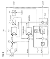
- Field weakening unit B9 ( FIG. 3 ) comprises a third calculation unit CU_3, which calculates the actual value m ACT of the modulation index here as an example depending on the setpoint value V d of the magnetic field-forming voltage and on the setpoint value V q of the torque-forming voltage.
- a difference between a desired value m MAX of the modulation index and the actual value m ACT of the modulation index is determined.
- the setpoint m MAX of the modulation index is typically set at values between 90% and 100%.
- the first difference signal m ⁇ determined from the difference may comprise a negative value if the actual value m ACT of the modulation index is greater than the setpoint value m MAX of the modulation index, for example when increasing the speed, typically above the rated speed of the synchronous machine PMSM, or at low supply voltages of the actuator S, which may be the case.
- a first controller B17 which is designed as a PI controller, detects the difference signal m ⁇ on the input side and, depending on this, determines a magnetic field- forming intermediate raw desired component I d, IntRefAux .
- the magnetic field- forming insects I d, IntRefAux the output side of the PI controller B17 on the input side is fed to a filter unit TP, which is preferably designed as a low-pass filter.
- the filter unit TP filters the magnetic field forming insects I d, IntRefAux in the sense of a low-pass. This will make the dependent From the magnetic field forming insects I d, IntRefAux determined setpoint I d, REF of the magnetic field-forming current for the subordinate pilot control B3 and the node VK3 of the subordinate d-controller B11 prefiltered.
- a second limiting unit B18 limits the input side applied magnetic field forming Rohsollstromkomponente I d, RefAux amount to the magnetic field forming current limit I d, MAX and determines the output side of the limited setpoint I d, REF of the magnetic field generating current, in FIG. 1 the pilot control B3 and the node VK3 is supplied.
- the magnetic field-forming current limit I d, MAX is thus preferably predetermined such that not only the resulting from the setpoint I d, REF of the magnetic field generating current current heat losses are kept low in the synchronous machine PMSM, but also the tilt limit associated control instability by limiting the setpoint I d, REF of the magnetic field forming current to the magnetic field forming current limit I d, MAX is prevented.
- the nominal value I d, REF of the magnetic field-forming current is fed to a first calculation unit CU_1 on the input side, which determines a torque-forming raw current limit value I q, MaxAux as a function of this and the maximum absolute current I dq, MAX which is also present on the input side.
- the determination of the torque-forming raw current limit value I q, MaxAux takes place according to the relationship F7 in FIG FIG.
- the value of the torque-forming current limit I q, MAX is assigned to the torque-forming raw current limit value I q, MaxAux .
- the maximum absolute current I dq, MAX and thus the maximum current of the actuator S is determined by the relationship F6 in FIG FIG. 2 not exceeded.
- a second difference signal I d, ⁇ is determined from a difference between the magnetic field forming Rohsollstromkomponente I d, RefAux and the magnetic field forming current limit I d, MAX .
- the second difference signal I d, ⁇ is fed to the input side of a second controller B19.
- the second controller B19 is preferably designed as a PI controller and may comprise an inverter on the input side, which inverts the second difference signal I d, ⁇ .
- the second PI controller B19 determines a torque- forming auxiliary current component I q, MaxMod depending on the input side applied differential signal I d, ⁇ .
- the second PI controller B19 can be designed such that it only the output torque- forming auxiliary current component I q, MaxMod determined when the magnetic field forming Rohsollstromkomponente I d, RefAux amount is greater than the magnetic field forming current limit I d, MAX .
- the torque- forming auxiliary current component I q, MaxMod can be preset by means of the second PI controller B19 on the output side with a value of 0.
- the second controller B19 designed as a PI controller could comprise an integrator reset mechanism which resets the integrator depending on suitable input values.
- the torque- forming auxiliary current component I q, MaxMod is fed on the input side to the first regulator B17 embodied as a PI controller.
- the first controller B17 also includes an input for the magnetic field-forming current limit I d, MAX .
- the first controller B17 is designed such that, given a value of the torque- forming auxiliary current component I q, MaxMod greater than 0, the current I component of the PI controller B17 is kept constant, so that no further unfavorable increase in magnitude of the magnetic field forming insects I d, IntRefAux is determined depending on the input side applied first difference signal m ⁇ .
- the first controller B17 and the second controller B19 are designed, for example, as PI controllers, but may also be designed as another controller known to the person skilled in the art as suitable for this purpose.
- the torque- forming auxiliary current component I q, MaxMod is fed to a second calculation unit CU_2 on the input side.
- the second calculation unit CU_2 pulls magnitude the likewise input side torque-forming Rohstromgrenzwert I q, MaxAux the value of the torque-forming auxiliary current component I q, MaxMod, and thereby determines the torque-forming current limit I q, MAX.
- the value of the torque-forming current limit I q, MAX becomes the first limiting unit B2 in FIG. 1 supplied, whereby the predetermined raw setpoint I q, REQ of the torque-forming current is limited.
- the torque-forming current limit I q, MAX can thus also be reduced in the case of limiting the setpoint value I d, REF of the magnetic field-forming current to the magnetic field-forming current limit I d, MAX , so that the current-limiting operation with the impressed maximum in field weakening operation absolute current I dq, MAX and thus the operation of the actuator S is left with the maximum current.
- I q, REF of the torque-generating current is given, which is actually required for the respective operation of the synchronous machine PMSM.
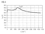
- FIG. 4 shows the time course of the absolute current I dq on the speed n of the synchronous machine PMSM.
- the time course is based on a measurement of a permanent-magnet synchronous machine PMSM as used for example in steering systems of motor vehicles.
- the synchronous machine has a rated speed of about 1000 min -1 .
- the synchronous machine PMSM starts from a predetermined Rohsollwert I q, REQ of the torque-forming current of 70A, the synchronous machine PMSM increases its speed during almost constant 70A up to a speed of 1000 min -1.
- a target value I d, REF of the magnetic field-forming current of 0 is given by the field weakening unit B9, that the maximum possible current I dq, MAX can be set to the maximum torque generation of the synchronous machine PMSM available.
- the torque request specifies a raw setpoint raw setpoint Iq
- REQ of the torque-generating current of 70A and the load of the drive system is such that the resulting torque excess accelerates the system
- the speed continues to increase.
- the field weakening operation by the field weakening unit B9 in FIG. 1 specified.
- the setpoint value I d, REF of the magnetic field-generating current is set greater than 0, in order to counteract the magnetic field of the permanent magnets of the rotor.
- the synchronous machine PMSM runs by means of the actuator S in the current limiting operation at about 80A, ie the absolute current I dq is equal to the maximum absolute current I dq, MAX , wherein the absolute current I dq by relationship F6 in FIG. 2 from a predetermined setpoint I d, REF and a maximum setpoint I q, MAX of the torque-generating current at this time. Also in this speed range, the predetermined setpoint I d, REF of the magnetic field generating current does not reach its predetermined current limit I d, MAX .
- the setpoint I d, REF of the magnetic field-generating current reaches the predetermined magnetic field-forming current limit I d, MAX .
- the injected current I dq, MAX of 80A would flow more min -1 constant from a speed of 1500 and the adjusting member S are thus continues to operate in current limit mode when the second controller B19 in FIG. 3 to determine the torque- forming auxiliary current component I q, MaxMod would not exist.
Landscapes
- Engineering & Computer Science (AREA)
- Power Engineering (AREA)
- Control Of Ac Motors In General (AREA)
Applications Claiming Priority (1)
| Application Number | Priority Date | Filing Date | Title |
|---|---|---|---|
| DE102007033145A DE102007033145A1 (de) | 2007-07-13 | 2007-07-13 | Vorrichtung zum Betreiben einer Synchronmaschine |
Publications (3)
| Publication Number | Publication Date |
|---|---|
| EP2015442A2 true EP2015442A2 (fr) | 2009-01-14 |
| EP2015442A3 EP2015442A3 (fr) | 2018-01-17 |
| EP2015442B1 EP2015442B1 (fr) | 2020-04-15 |
Family
ID=39929703
Family Applications (1)
| Application Number | Title | Priority Date | Filing Date |
|---|---|---|---|
| EP08104360.6A Active EP2015442B1 (fr) | 2007-07-13 | 2008-06-11 | Dispositif destiné au fonctionnement d'une machine synchrone |
Country Status (2)
| Country | Link |
|---|---|
| EP (1) | EP2015442B1 (fr) |
| DE (1) | DE102007033145A1 (fr) |
Cited By (2)
| Publication number | Priority date | Publication date | Assignee | Title |
|---|---|---|---|---|
| EP2662976A4 (fr) * | 2011-02-15 | 2015-11-11 | Sanden Corp | Dispositif de commande de moteur |
| WO2015176756A1 (fr) * | 2014-05-21 | 2015-11-26 | Continental Teves Ag & Co. Ohg | Procédé de commande d'un système de freinage |
Families Citing this family (3)
| Publication number | Priority date | Publication date | Assignee | Title |
|---|---|---|---|---|
| DE102013207727A1 (de) | 2013-04-26 | 2014-10-30 | Continental Teves Ag & Co. Ohg | Verfahren zur Ansteuerung eines bürstenlosen Motors |
| JP5880492B2 (ja) | 2013-07-03 | 2016-03-09 | 株式会社デンソー | 回転電機制御装置 |
| DE102014007632B4 (de) * | 2014-05-22 | 2016-03-24 | Audi Ag | Verfahren zum Regeln einer elektrischen Maschine |
Family Cites Families (4)
| Publication number | Priority date | Publication date | Assignee | Title |
|---|---|---|---|---|
| ATE180120T1 (de) * | 1996-11-04 | 1999-05-15 | Siemens Ag | Feldorientierte regelung einer drehfeldmaschine an der spannungsdecke |
| EP1317060A3 (fr) * | 2001-11-27 | 2004-04-14 | Siemens Aktiengesellschaft | Contrôle vectoriel d'une machine synchrone à aimants permanents avec un couple de reluctance |
| US6965212B1 (en) * | 2004-11-30 | 2005-11-15 | Honeywell International Inc. | Method and apparatus for field weakening control in an AC motor drive system |
| EP1777806A2 (fr) * | 2005-10-21 | 2007-04-25 | NSK Ltd. | Dispositif de commande d'un moteur électrique et de direction assistée électrique |
-
2007
- 2007-07-13 DE DE102007033145A patent/DE102007033145A1/de not_active Withdrawn
-
2008
- 2008-06-11 EP EP08104360.6A patent/EP2015442B1/fr active Active
Non-Patent Citations (1)
| Title |
|---|
| LEONHARD, W.: "Control of Electrical Drives", 1996, SPRINGER-VERLAG, pages: 309 - 317 |
Cited By (7)
| Publication number | Priority date | Publication date | Assignee | Title |
|---|---|---|---|---|
| EP2662976A4 (fr) * | 2011-02-15 | 2015-11-11 | Sanden Corp | Dispositif de commande de moteur |
| WO2015176756A1 (fr) * | 2014-05-21 | 2015-11-26 | Continental Teves Ag & Co. Ohg | Procédé de commande d'un système de freinage |
| KR20160148603A (ko) * | 2014-05-21 | 2016-12-26 | 콘티넨탈 테베스 아게 운트 코. 오하게 | 브레이크 시스템을 제어하기 위한 방법 |
| CN106416050A (zh) * | 2014-05-21 | 2017-02-15 | 大陆-特韦斯贸易合伙股份公司及两合公司 | 用于控制制动系统的方法 |
| US20170072924A1 (en) * | 2014-05-21 | 2017-03-16 | Continental Teves Ag & Co. Ohg | Method for Controlling a Brake System |
| CN106416050B (zh) * | 2014-05-21 | 2019-10-22 | 大陆-特韦斯贸易合伙股份公司及两合公司 | 用于控制制动系统的方法 |
| US10604127B2 (en) * | 2014-05-21 | 2020-03-31 | Continental Teves Ag & Co. Ohg | Method for controlling a brake system |
Also Published As
| Publication number | Publication date |
|---|---|
| EP2015442A3 (fr) | 2018-01-17 |
| EP2015442B1 (fr) | 2020-04-15 |
| DE102007033145A1 (de) | 2009-01-15 |
Similar Documents
| Publication | Publication Date | Title |
|---|---|---|
| DE102011009935B4 (de) | Verfahren zum Ansteuern eines optimalen Betriebspunktes bei einer Synchronmaschine und eine umrichtergespeiste Synchronmaschine | |
| EP1985007B1 (fr) | Procede et dispositif de fonctionnement d'une machine synchrone | |
| DE10206191B4 (de) | Verfahren zur feldorientierten Regelung einer permanenterregten Synchronmaschine mit Reluktanzmoment | |
| EP3145746B1 (fr) | Procédé de commande d'un système de freinage | |
| DE102008013799A1 (de) | Verfahren und System zur Steuerung von Permanentmagnet-AC-Maschinen | |
| EP3205014B1 (fr) | Dispositif de commande pour machine électrique, véhicule et procédé correspondant | |
| DE102007028229B3 (de) | Magnetlagersteuereinrichtung mit einem dreiphasigen Umrichter sowie Verwendung eines dreiphasigen Umrichters zur Steuerung eines Magnetlagers | |
| DE102007028635A1 (de) | Regel-/Steuervorrichtung für eine AC-Rotationsmaschine | |
| DE102008059708B4 (de) | Regelung einer permanentmagneterregten synchronen Drehfeldmaschine | |
| DE102015102565A1 (de) | Sensorloses Kommutierungsverfahren | |
| DE102004055042A1 (de) | Steuer-/Regelvorrichtung für einen bürstenlosen Motor und Steuer-/Regelverfahren für einen bürstenlosen Motor | |
| EP2015442B1 (fr) | Dispositif destiné au fonctionnement d'une machine synchrone | |
| DE102012205371A1 (de) | Reglerstruktur und Verfahren zur feldorientierten Regelung einer Drehfeldmaschine bei Feldschwächung | |
| DE102013207727A1 (de) | Verfahren zur Ansteuerung eines bürstenlosen Motors | |
| DE102012018819B4 (de) | Verfahren zum Betreiben eines Umrichters zur Speisung einer Elektromaschine und Elektromaschine | |
| EP0884834B1 (fr) | Procédé et dispositif pour la régulation de courant d'un moteur synchrone à aimant permanent et à f.e.m. trapézoidale et commandé par champ orienté | |
| DE102010021488A1 (de) | Verfahren zur (kupfer-)verlustoptimalen Regelung einer Asynchronmaschine mit einem Frequenzumrichter | |
| DE102014224158A1 (de) | Steuerung eines permanenterregten Synchronmotors | |
| EP3152829B1 (fr) | Procédé et dispositif de contrôle du fonctionnement d'un moteur électrique | |
| EP3449564B1 (fr) | Procédé et dispositif de commande d'une machine électrique | |
| WO2024217983A1 (fr) | Commande du courant statorique ou du flux statorique concaténé pour faire fonctionner une machine synchrone à excitation par aimants permanents, et procédé | |
| WO2024153299A1 (fr) | Procédé de commande vectorielle pour une machine synchrone, et unité de commande | |
| DE102013221939A1 (de) | Verfahren und Vorrichtung zum Betreiben eines elektronisch kommutierten Stellantriebs | |
| WO2021104763A1 (fr) | Procédé et dispositif de régulation d'une machine électrique | |
| EP1317060A2 (fr) | Contrôle vectoriel d'une machine synchrone à aimants permanents avec un couple de reluctance |
Legal Events
| Date | Code | Title | Description |
|---|---|---|---|
| PUAI | Public reference made under article 153(3) epc to a published international application that has entered the european phase |
Free format text: ORIGINAL CODE: 0009012 |
|
| AK | Designated contracting states |
Kind code of ref document: A2 Designated state(s): AT BE BG CH CY CZ DE DK EE ES FI FR GB GR HR HU IE IS IT LI LT LU LV MC MT NL NO PL PT RO SE SI SK TR |
|
| AX | Request for extension of the european patent |
Extension state: AL BA MK RS |
|
| PUAL | Search report despatched |
Free format text: ORIGINAL CODE: 0009013 |
|
| AK | Designated contracting states |
Kind code of ref document: A3 Designated state(s): AT BE BG CH CY CZ DE DK EE ES FI FR GB GR HR HU IE IS IT LI LT LU LV MC MT NL NO PL PT RO SE SI SK TR |
|
| AX | Request for extension of the european patent |
Extension state: AL BA MK RS |
|
| RIC1 | Information provided on ipc code assigned before grant |
Ipc: H02P 21/00 20160101AFI20171214BHEP |
|
| STAA | Information on the status of an ep patent application or granted ep patent |
Free format text: STATUS: REQUEST FOR EXAMINATION WAS MADE |
|
| 17P | Request for examination filed |
Effective date: 20180717 |
|
| RBV | Designated contracting states (corrected) |
Designated state(s): AT BE BG CH CY CZ DE DK EE ES FI FR GB GR HR HU IE IS IT LI LT LU LV MC MT NL NO PL PT RO SE SI SK TR |
|
| AKX | Designation fees paid |
Designated state(s): AT BE BG CH CY CZ DE DK EE ES FI FR GB GR HR HU IE IS IT LI LT LU LV MC MT NL NO PL PT RO SE SI SK TR |
|
| AXX | Extension fees paid |
Extension state: MK Extension state: RS Extension state: AL Extension state: BA |
|
| GRAP | Despatch of communication of intention to grant a patent |
Free format text: ORIGINAL CODE: EPIDOSNIGR1 |
|
| STAA | Information on the status of an ep patent application or granted ep patent |
Free format text: STATUS: GRANT OF PATENT IS INTENDED |
|
| RIC1 | Information provided on ipc code assigned before grant |
Ipc: H02P 21/00 20160101AFI20191025BHEP Ipc: H02P 25/03 20160101ALI20191025BHEP Ipc: H02P 21/22 20160101ALI20191025BHEP |
|
| INTG | Intention to grant announced |
Effective date: 20191125 |
|
| RIN1 | Information on inventor provided before grant (corrected) |
Inventor name: HEXAMER, BERND |
|
| GRAS | Grant fee paid |
Free format text: ORIGINAL CODE: EPIDOSNIGR3 |
|
| GRAA | (expected) grant |
Free format text: ORIGINAL CODE: 0009210 |
|
| STAA | Information on the status of an ep patent application or granted ep patent |
Free format text: STATUS: THE PATENT HAS BEEN GRANTED |
|
| AK | Designated contracting states |
Kind code of ref document: B1 Designated state(s): AT BE BG CH CY CZ DE DK EE ES FI FR GB GR HR HU IE IS IT LI LT LU LV MC MT NL NO PL PT RO SE SI SK TR |
|
| REG | Reference to a national code |
Ref country code: CH Ref legal event code: EP Ref country code: GB Ref legal event code: FG4D Free format text: NOT ENGLISH |
|
| REG | Reference to a national code |
Ref country code: DE Ref legal event code: R096 Ref document number: 502008017059 Country of ref document: DE |
|
| REG | Reference to a national code |
Ref country code: IE Ref legal event code: FG4D Free format text: LANGUAGE OF EP DOCUMENT: GERMAN |
|
| REG | Reference to a national code |
Ref country code: AT Ref legal event code: REF Ref document number: 1258476 Country of ref document: AT Kind code of ref document: T Effective date: 20200515 Ref country code: DE Ref legal event code: R084 Ref document number: 502008017059 Country of ref document: DE |
|
| RAP2 | Party data changed (patent owner data changed or rights of a patent transferred) |
Owner name: CONTINENTAL AUTOMOTIVE GMBH |
|
| REG | Reference to a national code |
Ref country code: NL Ref legal event code: MP Effective date: 20200415 |
|
| REG | Reference to a national code |
Ref country code: LT Ref legal event code: MG4D |
|
| PG25 | Lapsed in a contracting state [announced via postgrant information from national office to epo] |
Ref country code: IS Free format text: LAPSE BECAUSE OF FAILURE TO SUBMIT A TRANSLATION OF THE DESCRIPTION OR TO PAY THE FEE WITHIN THE PRESCRIBED TIME-LIMIT Effective date: 20200815 Ref country code: SE Free format text: LAPSE BECAUSE OF FAILURE TO SUBMIT A TRANSLATION OF THE DESCRIPTION OR TO PAY THE FEE WITHIN THE PRESCRIBED TIME-LIMIT Effective date: 20200415 Ref country code: FI Free format text: LAPSE BECAUSE OF FAILURE TO SUBMIT A TRANSLATION OF THE DESCRIPTION OR TO PAY THE FEE WITHIN THE PRESCRIBED TIME-LIMIT Effective date: 20200415 Ref country code: LT Free format text: LAPSE BECAUSE OF FAILURE TO SUBMIT A TRANSLATION OF THE DESCRIPTION OR TO PAY THE FEE WITHIN THE PRESCRIBED TIME-LIMIT Effective date: 20200415 Ref country code: NO Free format text: LAPSE BECAUSE OF FAILURE TO SUBMIT A TRANSLATION OF THE DESCRIPTION OR TO PAY THE FEE WITHIN THE PRESCRIBED TIME-LIMIT Effective date: 20200715 Ref country code: GR Free format text: LAPSE BECAUSE OF FAILURE TO SUBMIT A TRANSLATION OF THE DESCRIPTION OR TO PAY THE FEE WITHIN THE PRESCRIBED TIME-LIMIT Effective date: 20200716 Ref country code: PT Free format text: LAPSE BECAUSE OF FAILURE TO SUBMIT A TRANSLATION OF THE DESCRIPTION OR TO PAY THE FEE WITHIN THE PRESCRIBED TIME-LIMIT Effective date: 20200817 Ref country code: NL Free format text: LAPSE BECAUSE OF FAILURE TO SUBMIT A TRANSLATION OF THE DESCRIPTION OR TO PAY THE FEE WITHIN THE PRESCRIBED TIME-LIMIT Effective date: 20200415 |
|
| PG25 | Lapsed in a contracting state [announced via postgrant information from national office to epo] |
Ref country code: BG Free format text: LAPSE BECAUSE OF FAILURE TO SUBMIT A TRANSLATION OF THE DESCRIPTION OR TO PAY THE FEE WITHIN THE PRESCRIBED TIME-LIMIT Effective date: 20200715 Ref country code: HR Free format text: LAPSE BECAUSE OF FAILURE TO SUBMIT A TRANSLATION OF THE DESCRIPTION OR TO PAY THE FEE WITHIN THE PRESCRIBED TIME-LIMIT Effective date: 20200415 Ref country code: LV Free format text: LAPSE BECAUSE OF FAILURE TO SUBMIT A TRANSLATION OF THE DESCRIPTION OR TO PAY THE FEE WITHIN THE PRESCRIBED TIME-LIMIT Effective date: 20200415 |
|
| REG | Reference to a national code |
Ref country code: DE Ref legal event code: R097 Ref document number: 502008017059 Country of ref document: DE |
|
| PG25 | Lapsed in a contracting state [announced via postgrant information from national office to epo] |
Ref country code: RO Free format text: LAPSE BECAUSE OF FAILURE TO SUBMIT A TRANSLATION OF THE DESCRIPTION OR TO PAY THE FEE WITHIN THE PRESCRIBED TIME-LIMIT Effective date: 20200415 Ref country code: IT Free format text: LAPSE BECAUSE OF FAILURE TO SUBMIT A TRANSLATION OF THE DESCRIPTION OR TO PAY THE FEE WITHIN THE PRESCRIBED TIME-LIMIT Effective date: 20200415 Ref country code: DK Free format text: LAPSE BECAUSE OF FAILURE TO SUBMIT A TRANSLATION OF THE DESCRIPTION OR TO PAY THE FEE WITHIN THE PRESCRIBED TIME-LIMIT Effective date: 20200415 Ref country code: EE Free format text: LAPSE BECAUSE OF FAILURE TO SUBMIT A TRANSLATION OF THE DESCRIPTION OR TO PAY THE FEE WITHIN THE PRESCRIBED TIME-LIMIT Effective date: 20200415 Ref country code: ES Free format text: LAPSE BECAUSE OF FAILURE TO SUBMIT A TRANSLATION OF THE DESCRIPTION OR TO PAY THE FEE WITHIN THE PRESCRIBED TIME-LIMIT Effective date: 20200415 Ref country code: MC Free format text: LAPSE BECAUSE OF FAILURE TO SUBMIT A TRANSLATION OF THE DESCRIPTION OR TO PAY THE FEE WITHIN THE PRESCRIBED TIME-LIMIT Effective date: 20200415 Ref country code: CZ Free format text: LAPSE BECAUSE OF FAILURE TO SUBMIT A TRANSLATION OF THE DESCRIPTION OR TO PAY THE FEE WITHIN THE PRESCRIBED TIME-LIMIT Effective date: 20200415 |
|
| REG | Reference to a national code |
Ref country code: CH Ref legal event code: PL |
|
| PLBE | No opposition filed within time limit |
Free format text: ORIGINAL CODE: 0009261 |
|
| STAA | Information on the status of an ep patent application or granted ep patent |
Free format text: STATUS: NO OPPOSITION FILED WITHIN TIME LIMIT |
|
| PG25 | Lapsed in a contracting state [announced via postgrant information from national office to epo] |
Ref country code: PL Free format text: LAPSE BECAUSE OF FAILURE TO SUBMIT A TRANSLATION OF THE DESCRIPTION OR TO PAY THE FEE WITHIN THE PRESCRIBED TIME-LIMIT Effective date: 20200415 Ref country code: SK Free format text: LAPSE BECAUSE OF FAILURE TO SUBMIT A TRANSLATION OF THE DESCRIPTION OR TO PAY THE FEE WITHIN THE PRESCRIBED TIME-LIMIT Effective date: 20200415 |
|
| 26N | No opposition filed |
Effective date: 20210118 |
|
| GBPC | Gb: european patent ceased through non-payment of renewal fee |
Effective date: 20200715 |
|
| PG25 | Lapsed in a contracting state [announced via postgrant information from national office to epo] |
Ref country code: LU Free format text: LAPSE BECAUSE OF NON-PAYMENT OF DUE FEES Effective date: 20200611 |
|
| REG | Reference to a national code |
Ref country code: BE Ref legal event code: MM Effective date: 20200630 |
|
| PG25 | Lapsed in a contracting state [announced via postgrant information from national office to epo] |
Ref country code: GB Free format text: LAPSE BECAUSE OF NON-PAYMENT OF DUE FEES Effective date: 20200715 Ref country code: CH Free format text: LAPSE BECAUSE OF NON-PAYMENT OF DUE FEES Effective date: 20200630 Ref country code: LI Free format text: LAPSE BECAUSE OF NON-PAYMENT OF DUE FEES Effective date: 20200630 Ref country code: IE Free format text: LAPSE BECAUSE OF NON-PAYMENT OF DUE FEES Effective date: 20200611 |
|
| PG25 | Lapsed in a contracting state [announced via postgrant information from national office to epo] |
Ref country code: BE Free format text: LAPSE BECAUSE OF NON-PAYMENT OF DUE FEES Effective date: 20200630 Ref country code: SI Free format text: LAPSE BECAUSE OF FAILURE TO SUBMIT A TRANSLATION OF THE DESCRIPTION OR TO PAY THE FEE WITHIN THE PRESCRIBED TIME-LIMIT Effective date: 20200415 |
|
| REG | Reference to a national code |
Ref country code: AT Ref legal event code: MM01 Ref document number: 1258476 Country of ref document: AT Kind code of ref document: T Effective date: 20200611 |
|
| PG25 | Lapsed in a contracting state [announced via postgrant information from national office to epo] |
Ref country code: AT Free format text: LAPSE BECAUSE OF NON-PAYMENT OF DUE FEES Effective date: 20200611 |
|
| PG25 | Lapsed in a contracting state [announced via postgrant information from national office to epo] |
Ref country code: TR Free format text: LAPSE BECAUSE OF FAILURE TO SUBMIT A TRANSLATION OF THE DESCRIPTION OR TO PAY THE FEE WITHIN THE PRESCRIBED TIME-LIMIT Effective date: 20200415 Ref country code: MT Free format text: LAPSE BECAUSE OF FAILURE TO SUBMIT A TRANSLATION OF THE DESCRIPTION OR TO PAY THE FEE WITHIN THE PRESCRIBED TIME-LIMIT Effective date: 20200415 Ref country code: CY Free format text: LAPSE BECAUSE OF FAILURE TO SUBMIT A TRANSLATION OF THE DESCRIPTION OR TO PAY THE FEE WITHIN THE PRESCRIBED TIME-LIMIT Effective date: 20200415 |
|
| REG | Reference to a national code |
Ref country code: DE Ref legal event code: R081 Ref document number: 502008017059 Country of ref document: DE Owner name: CONTINENTAL AUTOMOTIVE TECHNOLOGIES GMBH, DE Free format text: FORMER OWNER: CONTINENTAL AUTOMOTIVE GMBH, 30165 HANNOVER, DE Ref country code: DE Ref legal event code: R081 Ref document number: 502008017059 Country of ref document: DE Owner name: AUMOVIO GERMANY GMBH, DE Free format text: FORMER OWNER: CONTINENTAL AUTOMOTIVE GMBH, 30165 HANNOVER, DE |
|
| P01 | Opt-out of the competence of the unified patent court (upc) registered |
Effective date: 20230522 |
|
| REG | Reference to a national code |
Ref country code: DE Ref legal event code: R081 Ref document number: 502008017059 Country of ref document: DE Owner name: CONTINENTAL AUTOMOTIVE TECHNOLOGIES GMBH, DE Free format text: FORMER OWNER: CONTINENTAL AUTOMOTIVE TECHNOLOGIES GMBH, 30165 HANNOVER, DE Ref country code: DE Ref legal event code: R081 Ref document number: 502008017059 Country of ref document: DE Owner name: AUMOVIO GERMANY GMBH, DE Free format text: FORMER OWNER: CONTINENTAL AUTOMOTIVE TECHNOLOGIES GMBH, 30165 HANNOVER, DE |
|
| PGFP | Annual fee paid to national office [announced via postgrant information from national office to epo] |
Ref country code: DE Payment date: 20240630 Year of fee payment: 17 |
|
| PGFP | Annual fee paid to national office [announced via postgrant information from national office to epo] |
Ref country code: FR Payment date: 20240628 Year of fee payment: 17 |
|
| REG | Reference to a national code |
Ref country code: DE Ref legal event code: R119 Ref document number: 502008017059 Country of ref document: DE |
|
| REG | Reference to a national code |
Ref country code: DE Ref legal event code: R081 Ref document number: 502008017059 Country of ref document: DE Owner name: AUMOVIO GERMANY GMBH, DE Free format text: FORMER OWNER: CONTINENTAL AUTOMOTIVE TECHNOLOGIES GMBH, 30175 HANNOVER, DE |
|
| PG25 | Lapsed in a contracting state [announced via postgrant information from national office to epo] |
Ref country code: DE Free format text: LAPSE BECAUSE OF NON-PAYMENT OF DUE FEES Effective date: 20260101 |
|
| PG25 | Lapsed in a contracting state [announced via postgrant information from national office to epo] |
Ref country code: FR Free format text: LAPSE BECAUSE OF NON-PAYMENT OF DUE FEES Effective date: 20250630 |