EP2015448A1 - Signalerfassungskette, die einen selektiven Frequenzabschwächer beinhaltet - Google Patents
Signalerfassungskette, die einen selektiven Frequenzabschwächer beinhaltet Download PDFInfo
- Publication number
- EP2015448A1 EP2015448A1 EP08159986A EP08159986A EP2015448A1 EP 2015448 A1 EP2015448 A1 EP 2015448A1 EP 08159986 A EP08159986 A EP 08159986A EP 08159986 A EP08159986 A EP 08159986A EP 2015448 A1 EP2015448 A1 EP 2015448A1
- Authority
- EP
- European Patent Office
- Prior art keywords
- attenuator
- frequency
- rejection
- selective
- module
- Prior art date
- Legal status (The legal status is an assumption and is not a legal conclusion. Google has not performed a legal analysis and makes no representation as to the accuracy of the status listed.)
- Withdrawn
Links
- 230000002441 reversible effect Effects 0.000 claims description 4
- 238000000034 method Methods 0.000 claims description 3
- 230000002238 attenuated effect Effects 0.000 description 11
- 238000001228 spectrum Methods 0.000 description 8
- 230000005540 biological transmission Effects 0.000 description 6
- 239000003990 capacitor Substances 0.000 description 4
- 230000009365 direct transmission Effects 0.000 description 4
- 230000009977 dual effect Effects 0.000 description 4
- 230000000903 blocking effect Effects 0.000 description 2
- 230000000295 complement effect Effects 0.000 description 2
- 230000000593 degrading effect Effects 0.000 description 2
- 238000010586 diagram Methods 0.000 description 2
- 238000005070 sampling Methods 0.000 description 2
- 230000009286 beneficial effect Effects 0.000 description 1
- 239000000919 ceramic Substances 0.000 description 1
- 230000000694 effects Effects 0.000 description 1
- 238000005516 engineering process Methods 0.000 description 1
- 238000002513 implantation Methods 0.000 description 1
- 230000002452 interceptive effect Effects 0.000 description 1
- 238000004519 manufacturing process Methods 0.000 description 1
- 230000003071 parasitic effect Effects 0.000 description 1
- 230000001105 regulatory effect Effects 0.000 description 1
- 230000003595 spectral effect Effects 0.000 description 1
- 238000011282 treatment Methods 0.000 description 1
Images


Classifications
-
- H—ELECTRICITY
- H03—ELECTRONIC CIRCUITRY
- H03H—IMPEDANCE NETWORKS, e.g. RESONANT CIRCUITS; RESONATORS
- H03H7/00—Multiple-port networks comprising only passive electrical elements as network components
- H03H7/01—Frequency selective two-port networks
- H03H7/06—Frequency selective two-port networks including resistors
- H03H7/07—Bridged T-filters
-
- H—ELECTRICITY
- H03—ELECTRONIC CIRCUITRY
- H03H—IMPEDANCE NETWORKS, e.g. RESONANT CIRCUITS; RESONATORS
- H03H7/00—Multiple-port networks comprising only passive electrical elements as network components
- H03H7/01—Frequency selective two-port networks
- H03H7/17—Structural details of sub-circuits of frequency selective networks
- H03H7/1741—Comprising typical LC combinations, irrespective of presence and location of additional resistors
- H03H7/1758—Series LC in shunt or branch path
-
- H—ELECTRICITY
- H03—ELECTRONIC CIRCUITRY
- H03H—IMPEDANCE NETWORKS, e.g. RESONANT CIRCUITS; RESONATORS
- H03H7/00—Multiple-port networks comprising only passive electrical elements as network components
- H03H7/01—Frequency selective two-port networks
- H03H7/17—Structural details of sub-circuits of frequency selective networks
- H03H7/1741—Comprising typical LC combinations, irrespective of presence and location of additional resistors
- H03H7/1775—Parallel LC in shunt or branch path
-
- H—ELECTRICITY
- H03—ELECTRONIC CIRCUITRY
- H03H—IMPEDANCE NETWORKS, e.g. RESONANT CIRCUITS; RESONATORS
- H03H7/00—Multiple-port networks comprising only passive electrical elements as network components
- H03H7/01—Frequency selective two-port networks
- H03H7/17—Structural details of sub-circuits of frequency selective networks
- H03H7/1741—Comprising typical LC combinations, irrespective of presence and location of additional resistors
- H03H7/1783—Combined LC in series path
-
- H—ELECTRICITY
- H03—ELECTRONIC CIRCUITRY
- H03H—IMPEDANCE NETWORKS, e.g. RESONANT CIRCUITS; RESONATORS
- H03H7/00—Multiple-port networks comprising only passive electrical elements as network components
- H03H7/01—Frequency selective two-port networks
- H03H7/17—Structural details of sub-circuits of frequency selective networks
- H03H7/1741—Comprising typical LC combinations, irrespective of presence and location of additional resistors
- H03H7/1791—Combined LC in shunt or branch path
-
- H—ELECTRICITY
- H04—ELECTRIC COMMUNICATION TECHNIQUE
- H04B—TRANSMISSION
- H04B3/00—Line transmission systems
- H04B3/02—Details
- H04B3/04—Control of transmission; Equalising
- H04B3/14—Control of transmission; Equalising characterised by the equalising network used
- H04B3/143—Control of transmission; Equalising characterised by the equalising network used using amplitude-frequency equalisers
- H04B3/144—Control of transmission; Equalising characterised by the equalising network used using amplitude-frequency equalisers fixed equalizers
Definitions
- the present invention relates to a signal acquisition chain having a frequency selective attenuator. It applies in particular to radio reception channels to reduce the power of signals present in certain frequency bands.
- Modern radio receivers are designed to deal with increasingly wide acquisition frequency bands with respect to the channelization of signals.
- One of the difficulties encountered in the production of reception channels is the acquisition of a low level signal in the presence of signals at high levels, while retaining information on the strong signals.
- this problem must be addressed especially for the direct digitization of large frequency bands in digital reception channels. Indeed, it is always possible to amplify weak signals, but this solution runs up against the limits of analog-digital converters (ADCs) which accept only a limited input voltage.
- ADCs analog-digital converters
- a direct scan receiver must be able to digitize a band of frequencies between 1 and 30 MHz, each signal being channeled on a 3kHz channel, all in a spectral environment disturbed by strong signals.
- signals broadcast on broadcast or broadcast tapes are particularly powerful and can be considered as interfering signals with respect to broadcast signals.
- ADC In order to allow the ADC to fully exploit the range of input voltages when sampling all signals of a wide frequency band, it is desirable to decrease the power of these strong signals.
- Attenuators are frequency invariant functions which means that the set of spectrum signals undergo attenuation.
- a A combination of attenuators and amplifiers would only result in an increase in the noise factor, and would therefore have no beneficial effect.
- Notch-type rejection filters which reject a frequency band while allowing the rest of the spectrum to pass.
- These filters are particularly bulky and expensive.
- the use of this type of filter makes it impossible to process signals in the rejected frequency band.
- the Notch filters have a Stationary Wave Ratio (ROS) much higher than 1 in the rejected frequency band and thus introduce phase discontinuities that prevent certain types of treatments, including goniometric calculations.
- ROS Stationary Wave Ratio
- the power attenuator module and the selective attenuator rejection modules are quadrupoles, one of the rejection modules of the pair being connected in parallel with the power attenuator module to form a third quadrupole said third quadrupole being connected in series with the other rejection module of the pair.
- the first selective attenuator rejection module comprises at least one parallel RLC circuit and the second selective attenuator rejection module comprises at least one series RLC circuit, the tuning frequencies of the RLC circuits being equal to the rejection frequencies.
- the first selective attenuator rejection module comprises at least one serial RLC circuit and the second selective attenuator rejection module comprises at least one parallel RLC circuit, the tuning frequencies of the circuits RLC being equal to the rejection frequencies.
- At least one series RLC circuit and at least one parallel RLC circuit comprises a variable capacitance diode for varying the tuning frequency F 0 .
- the acquisition system according to the invention is adapted to receive and process radio signals in the HF band.
- the signal acquisition chain according to the invention is reversible, the latter being adapted to receive and transmit signals passing through the selective frequency attenuator.
- a radio frequency reception channel having a frequency selective attenuator may be used to decrease the amplitude of signals transmitted on already known broadcast bands.
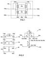
- the figure 1 shows an example of a frequency selective attenuator structure used in an acquisition system according to the invention.
- the selective frequency attenuator 100 is, in the example, a quadrupole comprising three quadrupoles: two rejectors 104, 106 and a power attenuator 102.
- the first rejector 104 is connected in parallel with the power attenuator 102, thus forming a quadrupole, which is connected in series with the second rejector 106.
- the selective frequency attenuator 100 has two inputs 100a, 100b and two outputs 100c, 100d
- the first rejector 104 has two inputs 104a, 104b and two outputs 104c and 104d
- the second rejector 106 has two inputs 106a. , 106b and two outputs 106c, 106d
- the power attenuator 102 has two inputs 102a, 102b and two outputs 102c, 102d.
- the first input 104a of the first rejector 104 is connected to the first input 1 02a of the power attenuator 102, these two inputs 104a, 102a being connected to the first input 100a of the frequency selective attenuator 100.
- the first output 104c of the first rejector 104 is connected to the first output 102c of the power attenuator 102, these two outputs 104c, 102c being connected to the first output 100c of the frequency selective attenuator 100.
- the second input 104b of the first rejector 104 is connected to the second input 102b of the power attenuator 102 and to the first input 106a of the second rejector 106.
- the second output 104d of the first rejector 104 is connected to the second output 102d of the power attenuator 102 and to the first output 106c of the second rejector 106.
- the second input 106b of the second rejector 106 is connected to the second input 100b of the selective frequency attenuator 100 and the second output 106d of the second rejector 106 is connected to the second output 100d of the frequency selective attenuator 100.
- the power attenuator 102 has the effect of reducing the power of an incoming signal. This function is invariant in frequencies, in other words, the power attenuator 102 attenuates the power of an incoming signal in the same way whatever the frequency of this signal.
- the first and second rejectors 104, 106 are designed to operate concurrently and in a complementary manner. For example, when the first rejector 104 makes a short circuit between the first input and output 100a, 100c of the frequency selective attenuator 100, the second rejector 106 isolates said input and output of the second inputs and outputs 100b, 100d.
- the two rejectors 104, 106 are designed so that the power transmitted by each of them evolves in a complementary manner as a function of the frequency of the input signal.
- the two rejectors 104, 106 can be tuned on the same frequency F 0 , such that a signal entering the frequency-selective attenuator 100, the frequency of which is close to F 0 , is very strongly attenuated at the output 100c, 100d and an incoming signal whose frequency is remote from F 0 is transmitted almost without attenuation output.
- the selective attenuator 100 is designed so that its input and output impedances are controlled. For example, for a radio signal reception channel, an impedance value of 50 ohms is generally chosen. Generally, the attenuation level of the power attenuator 102 is chosen in a first step, then the values of the rejection frequencies of the two rejectors 104, 106 are chosen.
- a selective attenuator 100 in a signal acquisition chain for example a radio signal acquisition chain, makes it possible to attenuate disturbing signals without degrading the information content, so that the attenuated signals can still be analyzed, unlike an equalizer circuit, which behaves like a level compensator.
- the figure 2 presents a first embodiment of a frequency selective attenuator used in an acquisition system according to the invention.
- the first rejector 104 is a quadrupole having a parallel RLC circuit.
- a circuit R p L p C p formed of a resistor Rp, a inductance Lp and a capacitor Cp connected in parallel connects the first input 104a to the first output 104c of the first quadrupole rejector 104.
- the second input 104b is connected to the second output 104d by a wire.
- the first input 106a of the second rejector 106 is connected to its first output 106c by a wire, as its second input 106b is connected by a wire to the second output 106d.
- a circuit R s L s C s formed by a resistor R s , a inductance L s , and a capacitance C s connected in series, is placed between the first input and output 106a, 106c and the second input and output 106b, 106d .
- the second input and output 106b, 106d of the second rejector are electrically grounded.
- the power attenuator 102 presented in figure 2 is a T-attenuator, having two resistors R1, R2 placed in series between the first input 102a and the first output 102c.
- the power attenuator 102 also has a third resistor R3 connecting the junction of the first two resistors R1, R2 with the second input and output 102b, 102d, said input and output being connected to each other by a wire.
- the power attenuator 102 has a en structure.
- the RLC circuits present in the first and second rejectors 104, 106 are designed to have substantially the same tuning frequency F 0 . Moreover, the values of the inductances and capacitors of these circuits R p L p C p , R s L s C s have an impact on the quality factor, ie the selectivity of the filter.
- the tuning frequency of the circuit R p L p C p of the first rejector 104 is a function of the product Lp.Cp.
- the tuning frequency of the circuit R s L s C s of the second rejector 106 is a function of the product L s .C s .
- the pairs of values (L p , C p ) and (L s .C s ) are in particular determined as a function of the target tuning frequency F 0 and the desired selectivity.
- the frequency F 0 corresponds to the frequency of the disturbing signals to be attenuated and the selectivity corresponds to the frequency band to be covered around this frequency F 0 .
- the series resistance R s is the loss resistance due in particular to the resistive appearance of the series inductance L s .
- the value of this series resistance R s depends on the value of the quality coefficient of the series inductance L s .
- the inductance L s is chosen so that the value R s is almost zero.
- the value of the parallel resistance Rp depends on the value of the quality coefficient of the parallel inductance Lp, which is chosen so that the value Rp is much greater than the values of the resistors R1, R2, and R3 of the
- the rejectors may comprise several inductances and / or several capacitors in order to obtain a greater rejection selectivity.
- the inductances belonging to the same rejector can be aligned during hardware implantation to create a mutual inductance.
- the capacitances C s , Cp used in the RLC circuits can be fixed or variable. These capacities are tunable by current or by voltage. For example, to vary the tuning frequency F 0 , a variable capacitance diode can be used.
- the RLC circuits can be replaced by other resonant circuits including, for example, ceramic bars.
- the first rejector 104 tends to short-circuit its first input 104a with its first output 104c, thanks to the quasi-zero impedance of the inductance Lp at low frequencies.
- the second rejector tends to open the circuit between its first input and output 106a, 106c and its second input and output 106b, 106d, the capacitance C s blocking the passage of electric current at low frequencies.
- the selective frequency attenuator 100 tends to behave as a simple transmission line, allowing the signal to pass without significantly modifying it.
- the first rejector 104 tends to short-circuit its first input 104a with its first output 104c, thanks to the quasi-zero impedance of the capacitance Cp at high frequencies.
- the second rejector tends to open the circuit between its first input and output 106a, 106c and its second input and output 106b, 106d, the inductance L s blocking the passage of electric current at high frequencies.
- the selective frequency attenuator 100 tends to behave as a simple transmission line, allowing the signal to pass without significantly modifying it.
- the circuit R p L p C p of the first rejector 104 behaves substantially as an open circuit with respect to the power attenuator 102, since the resistance parallel Rp is much greater than the resistors component attenuator 102. Meanwhile, at the circuit R s L s C s series the second rejector 106, a short circuit is almost made between the power attenuator 102 and the electrical mass, because the series resistor R s is very low. Thus, when the frequency of the incoming signal is close to F 0 , the influence of the two rejector circuits 104, 106 is largely inhibited and the selective frequency attenuator 100 behaves substantially as a conventional attenuator.
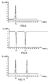
- the figure 3 illustrates, by a curve, the evolution of the direct transmission coefficient S21 of the frequency selective attenuator according to the first embodiment presented in FIG. figure 2 depending on the frequency of the incoming signal. Thanks to the combination of the two rejectors 104, 106 around the attenuator 102, only the signals whose frequency is close to the frequency F 0 are attenuated, the rest of the frequency spectrum is not altered. In addition, the ROS, not shown in the figure, remains almost equal to 1 whatever the frequency of the input signal and the phase of the signals is little changed. Moreover, the reflection coefficient S11 is close to the characteristic impedance of the selective attenuator quadrupole1 00.
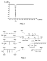
- the figure 4 presents a second embodiment of a frequency-selective attenuator used in an acquisition system according to the invention.
- the objective sought is to attenuate the signals of all frequencies, with the exception of those whose frequency is close to the tuning frequency F 0 .
- the function sought is therefore the dual function of the transmission function illustrated in FIG. figure 3 .
- the frequency-selective attenuator 100 ' comprises two rejectors 104', 106 '.
- the first rejector 104 ' comprises a series R s L s C s circuit placed in parallel with the power attenuator 102, while the second rejector 106' comprises a parallel R p L p C p placed in series with the attenuator 102.
- the first quadrupole rejector 104 and the second quadrupole rejector 106 have each been replaced respectively by their dual quadrupole 104 'and 106'.
- the first rejector 104 comprises a circuit R s L s C s series placed between its first input 104a' and its first output 104c ', while the second input and output 104b', 104d 'are connected by a thread.
- the influence of the two rejector circuits 104 ', 106' is largely inhibited and the selective frequency attenuator 100 'behaves substantially like a conventional attenuator .
- the first rejector circuit 104 When the frequency of the incoming signal is close to the tuning frequency F 0 , the first rejector circuit 104 'tends to short-circuit its first input 104a' with its first output 104c ', since the resistor R s of the circuit R s L s C s series is very small. At the same time, the circuit R p L p C p of the second rejector 106 'opposes a significant resistor Rp to the passage of the current.
- the selective frequency attenuator 100 when the frequency of the incoming signal is close to the tuning frequency F 0 , the selective frequency attenuator 100 'tends to behave as a simple transmission line, allowing the signal to pass without significantly modifying it.
- the figure 5 illustrates, by a curve, the evolution of the direct transmission coefficient S21 of the frequency selective attenuator according to the second embodiment presented in FIG. figure 4 depending on the frequency of the incoming signal.
- the signals of all the frequencies are attenuated.
- the ROS remains, in the case of this embodiment, almost equal to 1 whatever the frequency of the input signal and the phase of the signals is little modified, including around the tuning frequency F 0 .
- the reflection coefficient S11 is close to the characteristic impedance of the selective attenuator quadrupole 100.
- the figure 6 presents a generalization of the frequency-selective attenuator structure presented in figure 1 .
- the frequency selective attenuator 600 comprises a first rejection module 611 comprising two cascade quadrupoles 604, 605 mounted in cascade, said module being connected in parallel with a power attenuator 102.
- a second rejection module 612 comprises two rejection quadrupoles. 606, 607 connected in parallel, this second module being connected in series with the power attenuator 102.
- the first output 604c of the first rejection quadrupole 604 is connected to the first input 605a of the second quadrupole 605 and the second output 604d of the first rejection quadrupole 604 is connected to the second input 605b of the second quadrupole 605.
- the first rejection module 611 thus formed replaces the quadrupole rejector 104 of the figure 1 .
- the second rejection module 612 replaces the second quadrupole rejector 106 of the structure of the figure 1 the other connections being identical to those of the first embodiment.
- rejectors may be cascaded and paralleled.
- the rejectors are associated in pairs, each pair corresponding to a frequency attenuation zone of the power. To add such an attenuation zone in the spectrum, it is therefore necessary to add a new pair of rejectors, the first of which is cascaded with the rejectors 604, 605 of the first rejection module 611, and the second being connected in parallel with the rejectors 606, 607 of the second rejection module 612.
- the figure 7 presents an embodiment corresponding to the generalized structure of the figure 6 .
- the frequency selective attenuator 600 comprises two pairs of rejectors.
- the rejector quadrupoles 604, 605 connected to the first input and output 600a, 600c of the frequency selective attenuator 600 are, in the example, the same as the first quadrupole rejector 104 of the figure 2 .
- the rejector quadrupoles 606, 607 connected to the second input and output 600b, 600d of the frequency selective attenuator 600 are, in the example, the same as the second quadrupole rejector 106 of the figure 2 .
- This frequency-selective attenuator 600 is therefore different from the first embodiment presented in figure 2 by adding two RLC circuits.
- a circuit R p L p 'C p' parallel is connected in series to the circuit R p L p C p already present in the first notch 104 and a circuit R s L s 'C s' series is connected in parallel with the circuit R s L s C s already present in the second rejector 106.
- Each pair of circuits R s L s C s / R p L p C p and R s ' L s ' C s ' / R p 'L p ' C p ' operates independently of the other the first pair R s L s C s / R p L p C p operating at a tuning frequency F 0 , and the second pair R s ' L s 'C s ' / R p 'L p ' C p 'operating at another tuning frequency F 1 .
- the cascading of the circuits R p L p C p , R p 'L p ' C p ' makes it possible to perform a logical "or” on the function of opening the circuit between the first input and output 102a, 102c of the power attenuator 102.
- the parallel connection of the circuits R s L s C s, R s' s L 'C s' series can perform an "or" logic on the shorting function of the second input and output 102b, 102d of the power attenuator 102 with the electrical ground.
- the frequency selective attenuator 600 attenuates only the signals whose frequencies are close to the frequencies F 0 and F 1 .
- the figure 8 illustrates, by a curve, the evolution of the direct transmission coefficient S21 of the frequency selective attenuator according to the third embodiment presented in FIG. figure 7 depending on the frequency of the incoming signal. With the exception of a frequency band around F 0 and F 1 , the signals of all frequencies are attenuated.
- the figure 9 has a frequency-selective attenuator structure that achieves an attenuation function dual to that presented in FIG. figure 8 .
- the objective is to attenuate the signals of the entire spectrum with the exception of two areas for which the signals are not attenuated.
- the selective frequency attenuator 900 comprises a first rejection module 911 comprising two parallel quadrupoles 904, 905 connected in parallel, said module being connected in parallel with a power attenuator 102.
- a second rejection module 912 comprises two rejection quadrupoles 906, 907 mounted in series, this second module being connected in series with the power attenuator 102.
- the figure 10 presents an embodiment corresponding to the structure of the figure 9 .
- the rejector quadrupoles 904, 905 connected to the first input and output 900a, 900c of the frequency selective attenuator 900 are, in the example, the same as the first quadrupole rejector 104 'of the figure 4 .
- the rejector quadrupoles 906, 907 connected to the second input and output 900b, 900d of the frequency-selective attenuator 900 are, in the example, the same as the second rejection quadrupole 106 'of the figure 4 .
- This selective frequency attenuator 900 is therefore different from the first embodiment presented in figure 4 by adding two RLC circuits.
- a first circuit R s L s' C s' series is connected in parallel with the circuit R s L s C s already present in the first notch 104 'and a second circuit R p L p' C p 'parallel is associated in series to the circuit R p L p C p already present in the second rejector 106 '.
- Each pair of circuits R s L s C s / R p L p C p and R s 'L s ' C s '/ R p ' L p 'C p ' operates independently of one another the first pair R s L s C s / R p L p C p corresponding to a tuning frequency F 0 , and the second pair R s 'L s ' C s '/ R p ' L p 'C p ' corresponding to another frequency agree F 1 .
- the series setting of the circuits R p L p C p , R p 'L p ' C p ' makes it possible to perform a logical "or” on the function of opening the circuit between the second input and output 1 02b, 102d of the power attenuator 102 and the electrical ground.
- the paralleling of the circuits R s L s C s , R s ' L s ' C s ' series makes it possible to perform a logic "or” on the short-circuiting function of the first input and output 102a , 102c of the attenuator power 102.
- the only signals not attenuated by the frequency selective attenuator 900 are those whose frequencies are close to the frequencies F 0 and F 1 .
- the figure 11 illustrates, by a curve, the evolution of the direct transmission coefficient S21 of the frequency selective attenuator according to the fourth embodiment presented in FIG. figure 10 depending on the frequency of the incoming signal. With the exception of a frequency band around F 0 and F 1 , the signals of all frequencies are attenuated.
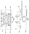
- the figure 12 is a block diagram of a radio frequency reception channel according to the invention comprising a selective frequency attenuator.
- the reception channel 1200 comprises a programmable attenuator 1204 receiving a signal from an antenna 1202.
- the attenuation level applied by the programmable attenuator 1204 is set via a control signal 1205.
- the signal from said attenuator 1204 is then received. by a first filter 1206 for retaining only part of the frequency spectrum of the signal. At this point, the signal still includes frequency components whose power is too high.
- the signal from the first filter 1206 is received by a frequency selective attenuator 1208.
- the frequency selective attenuator 1208 only attenuates the frequency components transmitted with too much power.
- An amplifier 1210 is placed at the output of the frequency-selective attenuator 1208, then the signal from this amplifier is received by a second programmable attenuator 1212 performing an automatic gain control regulated by a control signal 1213.
- the output of the programmable attenuator 1212 is connected to a second filter 1214, which is an anti-aliasing filter making it possible to comply with the Shannon condition before sampling performed by a CAN 1216 placed at the output of this second filter 1214.
- the selective frequency attenuator 1208 can be deactivated in the reception chain by means of a switching module 1209 for transmitting the signal directly from the first filter 1206 to the amplifier 1210. According to another embodiment, several selective attenuators 1208 can be cascaded.
- the frequency selective attenuator 1208 is, in the example, placed among the first stages of the reception channel 1200 because it hardly affects the noise factor of this channel 1200.
- the selective attenuator 1208 can also be used alternately in reception mode and in transmission mode in order, for example, to attenuate any parasitic lines generated by the reversible acquisition system when it is in the operating mode. program.
- a selective attenuator 1208 can operate in both directions of transmission receive / transmit, its input impedance being equal to its output impedance.
- the selective frequency attenuator used in an acquisition system according to the invention can be realized with discrete components such as coils and capacitors, or with any other technology allowing the combination of quadrupoles. It requires few components, which makes it compact and inexpensive.
- One of the important advantages of using a frequency-selective attenuator in an acquisition chain is that it provides very good intermodulation performance.
- the attenuator structure can be applied in acoustic signal acquisition chains.
Landscapes
- Engineering & Computer Science (AREA)
- Computer Networks & Wireless Communication (AREA)
- Signal Processing (AREA)
- Input Circuits Of Receivers And Coupling Of Receivers And Audio Equipment (AREA)
- Transmitters (AREA)
Applications Claiming Priority (1)
| Application Number | Priority Date | Filing Date | Title |
|---|---|---|---|
| FR0704993A FR2918821B1 (fr) | 2007-07-10 | 2007-07-10 | Attenuateur selectif en frequences |
Publications (1)
| Publication Number | Publication Date |
|---|---|
| EP2015448A1 true EP2015448A1 (de) | 2009-01-14 |
Family
ID=39146982
Family Applications (1)
| Application Number | Title | Priority Date | Filing Date |
|---|---|---|---|
| EP08159986A Withdrawn EP2015448A1 (de) | 2007-07-10 | 2008-07-09 | Signalerfassungskette, die einen selektiven Frequenzabschwächer beinhaltet |
Country Status (3)
| Country | Link |
|---|---|
| EP (1) | EP2015448A1 (de) |
| FR (1) | FR2918821B1 (de) |
| SA (1) | SA08290420B1 (de) |
Families Citing this family (1)
| Publication number | Priority date | Publication date | Assignee | Title |
|---|---|---|---|---|
| FR2953342B1 (fr) * | 2009-12-01 | 2012-01-20 | Thales Sa | Attenuateur selectif en frequences pourvu d'une structure en t aisement accordable |
Citations (10)
| Publication number | Priority date | Publication date | Assignee | Title |
|---|---|---|---|---|
| CH385292A (de) * | 1954-10-21 | 1964-12-15 | Standard Telephon & Radio Ag | Verfahren zur Entzerrung von elektrischen Signalübertragungskanälen |
| GB1338180A (en) * | 1970-12-11 | 1973-11-21 | Int Standard Electric Corp | Electric circuits |
| FR2315806A1 (fr) * | 1975-06-24 | 1977-01-21 | Portenseigne | Dispositif pour la correction dans une tres large bande de frequences des caracteristiques d'affaiblissement des signaux transmis par cable de teledistribution en fonction des variations de la temperature dudit cable |
| FR2460073A1 (fr) * | 1979-06-25 | 1981-01-16 | Elap | Egaliseur variable capable de pente nulle |
| JPS6110308A (ja) * | 1984-06-26 | 1986-01-17 | Mitsubishi Electric Corp | 可変等化器 |
| DE9407183U1 (de) * | 1994-05-03 | 1994-07-07 | Fuba Hans Kolbe & Co, 31134 Hildesheim | Entzerrerschaltung |
| JPH0715201A (ja) * | 1993-06-28 | 1995-01-17 | Kokusai Electric Co Ltd | 減衰等化器 |
| FR2712750A1 (fr) * | 1993-11-19 | 1995-05-24 | Thomson Csf | Dispositif de commande automatique de gain dans une chaîne de réception radiofréquence. |
| JPH0897766A (ja) * | 1994-09-28 | 1996-04-12 | Toshiba Corp | 受信回路 |
| EP1137189A2 (de) * | 2000-03-22 | 2001-09-26 | Lucent Technologies Inc. | Hochleistungsselektiver Signaldämpfer und Dämpfungsverfahren |
-
2007
- 2007-07-10 FR FR0704993A patent/FR2918821B1/fr active Active
-
2008
- 2008-07-09 EP EP08159986A patent/EP2015448A1/de not_active Withdrawn
- 2008-07-09 SA SA08290420A patent/SA08290420B1/ar unknown
Patent Citations (10)
| Publication number | Priority date | Publication date | Assignee | Title |
|---|---|---|---|---|
| CH385292A (de) * | 1954-10-21 | 1964-12-15 | Standard Telephon & Radio Ag | Verfahren zur Entzerrung von elektrischen Signalübertragungskanälen |
| GB1338180A (en) * | 1970-12-11 | 1973-11-21 | Int Standard Electric Corp | Electric circuits |
| FR2315806A1 (fr) * | 1975-06-24 | 1977-01-21 | Portenseigne | Dispositif pour la correction dans une tres large bande de frequences des caracteristiques d'affaiblissement des signaux transmis par cable de teledistribution en fonction des variations de la temperature dudit cable |
| FR2460073A1 (fr) * | 1979-06-25 | 1981-01-16 | Elap | Egaliseur variable capable de pente nulle |
| JPS6110308A (ja) * | 1984-06-26 | 1986-01-17 | Mitsubishi Electric Corp | 可変等化器 |
| JPH0715201A (ja) * | 1993-06-28 | 1995-01-17 | Kokusai Electric Co Ltd | 減衰等化器 |
| FR2712750A1 (fr) * | 1993-11-19 | 1995-05-24 | Thomson Csf | Dispositif de commande automatique de gain dans une chaîne de réception radiofréquence. |
| DE9407183U1 (de) * | 1994-05-03 | 1994-07-07 | Fuba Hans Kolbe & Co, 31134 Hildesheim | Entzerrerschaltung |
| JPH0897766A (ja) * | 1994-09-28 | 1996-04-12 | Toshiba Corp | 受信回路 |
| EP1137189A2 (de) * | 2000-03-22 | 2001-09-26 | Lucent Technologies Inc. | Hochleistungsselektiver Signaldämpfer und Dämpfungsverfahren |
Also Published As
| Publication number | Publication date |
|---|---|
| FR2918821B1 (fr) | 2009-11-20 |
| SA08290420B1 (ar) | 2013-06-22 |
| FR2918821A1 (fr) | 2009-01-16 |
Similar Documents
| Publication | Publication Date | Title |
|---|---|---|
| EP1863116B1 (de) | Breitbandrichtkoppler | |
| FR2919107A1 (fr) | Attenuateur par echelon. | |
| FR2918235A1 (fr) | Filtre canal, notamment pour un recepteur de television numerique. | |
| EP1429458A2 (de) | Transformator mit Moduswechsel und Frequenzauswahl | |
| WO2021165210A1 (fr) | Circuit intégré comportant un réseau d'adaptation et de filtrage et procédé d'adaptation et de filtrage correspondant | |
| FR3008238A1 (fr) | Filtre rejecteur de bande | |
| EP0792027B1 (de) | Mehrband-Funkgerät | |
| EP2015448A1 (de) | Signalerfassungskette, die einen selektiven Frequenzabschwächer beinhaltet | |
| EP3255806B1 (de) | Verzögerungsschaltkreis für die zeitliche verzögerung eines funkfrequenzsignals, und vorrichtung zur interferenzreduzierung, die einen solchen schaltkreis nutzt | |
| FR2802737A1 (fr) | Composant composite pour hautes frequences et appareil de telecommunications mobile l'incorporant | |
| EP0273793B1 (de) | Hochselektiver Fallenkreis und Benutzung eines solchen Fallenkreises | |
| WO2011067178A1 (fr) | Attenuateur selectif en frequences pourvu d'une structure en t aisement accordable | |
| FR3120279A1 (fr) | Calibration d'un atténuateur RF | |
| FR2904492A1 (fr) | Circuit de filtrage dote de resonateurs acoustiques | |
| EP0337825B1 (de) | Mikrowellensperrfilter in Mikrostreifenausführung | |
| EP1298792A1 (de) | Gilbert-Multiplizierer-Zelle Mischer | |
| FR2493632A1 (de) | ||
| FR2974454A1 (fr) | Duplexeur frequentiel a faible masse et faible encombrement | |
| EP0293287B1 (de) | Testeinrichtung für einen Phasendemodulator mit Spreizspektrum | |
| EP1193887B1 (de) | Verfahren und Schaltung eines Multibandempfänger in einem Mobilfunktelefon | |
| WO2011009905A1 (fr) | Structure hyperfréquences de commutation à amplificateur distribué avec entrée d'injection de signal de test | |
| FR3129037A1 (fr) | Dispositif de filtrage reconfigurable et système d'acquisition de signaux radiofréquences intégrant un tel dispositif de filtrage | |
| FR2955220A1 (fr) | Filtre actif a bande passante modulable | |
| EP0312145A1 (de) | Aktive, einen RC-Filter bildende Schaltung für Bandsperre oder Allpass-Anwendung | |
| EP0780973B1 (de) | Kerbfilter mit passiven Elementen |
Legal Events
| Date | Code | Title | Description |
|---|---|---|---|
| PUAI | Public reference made under article 153(3) epc to a published international application that has entered the european phase |
Free format text: ORIGINAL CODE: 0009012 |
|
| AK | Designated contracting states |
Kind code of ref document: A1 Designated state(s): AT BE BG CH CY CZ DE DK EE ES FI FR GB GR HR HU IE IS IT LI LT LU LV MC MT NL NO PL PT RO SE SI SK TR |
|
| AX | Request for extension of the european patent |
Extension state: AL BA MK RS |
|
| 17P | Request for examination filed |
Effective date: 20090713 |
|
| 17Q | First examination report despatched |
Effective date: 20090807 |
|
| AKX | Designation fees paid |
Designated state(s): AT BE BG CH CY CZ DE DK EE ES FI FR GB GR HR HU IE IS IT LI LT LU LV MC MT NL NO PL PT RO SE SI SK TR |
|
| STAA | Information on the status of an ep patent application or granted ep patent |
Free format text: STATUS: THE APPLICATION IS DEEMED TO BE WITHDRAWN |
|
| 18D | Application deemed to be withdrawn |
Effective date: 20130522 |