EP2015512B1 - Verfahren und system zum erkennen und melden des ausfalls der datenübertragungseinrichtung - Google Patents
Verfahren und system zum erkennen und melden des ausfalls der datenübertragungseinrichtung Download PDFInfo
- Publication number
- EP2015512B1 EP2015512B1 EP07720564A EP07720564A EP2015512B1 EP 2015512 B1 EP2015512 B1 EP 2015512B1 EP 07720564 A EP07720564 A EP 07720564A EP 07720564 A EP07720564 A EP 07720564A EP 2015512 B1 EP2015512 B1 EP 2015512B1
- Authority
- EP
- European Patent Office
- Prior art keywords
- data transmission
- transmission equipment
- state information
- fault
- peer
- Prior art date
- Legal status (The legal status is an assumption and is not a legal conclusion. Google has not performed a legal analysis and makes no representation as to the accuracy of the status listed.)
- Active
Links
- 230000005540 biological transmission Effects 0.000 title claims abstract description 171
- 238000000034 method Methods 0.000 title claims abstract description 19
- 238000012423 maintenance Methods 0.000 claims description 8
- 238000004134 energy conservation Methods 0.000 claims description 6
- 238000004891 communication Methods 0.000 abstract description 14
- 101150071746 Pbsn gene Proteins 0.000 description 12
- 238000001514 detection method Methods 0.000 description 8
- DWSYCUKCNSVBRA-UHFFFAOYSA-N 4-(5-methylsulfonyltetrazol-1-yl)phenol Chemical compound CS(=O)(=O)C1=NN=NN1C1=CC=C(C=C1)O DWSYCUKCNSVBRA-UHFFFAOYSA-N 0.000 description 7
- 101710167643 Serine/threonine protein phosphatase PstP Proteins 0.000 description 7
- 239000000835 fiber Substances 0.000 description 7
- 230000003993 interaction Effects 0.000 description 2
- 238000012986 modification Methods 0.000 description 2
- 230000004048 modification Effects 0.000 description 2
- 230000001419 dependent effect Effects 0.000 description 1
- 238000010586 diagram Methods 0.000 description 1
- 238000005259 measurement Methods 0.000 description 1
- 238000012544 monitoring process Methods 0.000 description 1
- 238000011160 research Methods 0.000 description 1
- 238000012360 testing method Methods 0.000 description 1
- 238000012546 transfer Methods 0.000 description 1
Images




Classifications
-
- H—ELECTRICITY
- H04—ELECTRIC COMMUNICATION TECHNIQUE
- H04L—TRANSMISSION OF DIGITAL INFORMATION, e.g. TELEGRAPHIC COMMUNICATION
- H04L41/00—Arrangements for maintenance, administration or management of data switching networks, e.g. of packet switching networks
- H04L41/06—Management of faults, events, alarms or notifications
- H04L41/0677—Localisation of faults
Definitions
- the present invention relates to the network operation and maintenance field, and in particular, to a method and a system for detecting and reporting faults of data transmission equipment.
- US application of No. 2004/153835 discloses an automated kernel software outage measurement and classification in order to automatically distinguish operations related to software outage events.
- System failures are categorized into software-caused failures and hardware-caused failures.
- Software failures are further classified as unplanned outages and operational outages.
- the operational outages are then classified as unplanned operational outages and planned operational outages.
- the failures for the different categories are then automatically measured.
- the network transmission of network equipment is vulnerable to interruption due to link failure or power failure.
- Network equipment generally has a dedicated channel for data interaction with the Network Management System (NMS) or has the function of transmitting interaction information through traffic overhead, thus implementing network management and monitoring.
- NMS Network Management System
- Link failure includes fiber cut and coax cable fault.
- a piece of equipment is installed tens of kilometers away, and is connected with the local equipment through fibers. Without additional communication means, it is impossible to know whether the remote equipment is power off or not.
- the local equipment can detect signal loss, but is unable to know whether the signal loss is caused by fiber cut or equipment power failure, or to obtain the information about equipment power failure.
- the prior art uses a dedicated power detection device and a dedicated auxiliary communication circuit, both relying on a standby power supply (such as battery) to work.
- a standby power supply such as battery
- a method and a system for detecting and reporting faults of data transmission equipment provided in an embodiment of the present invention can detect the fault causes of the network equipment and report in real time, so that the NMS can handle the network equipment faults during the data transmission timely and accurately.
- An embodiment of the present invention provides a method for detecting and reporting faults of data transmission equipment, including:
- An embodiment of the present invention further provides a data transmission equipment, including:
- An embodiment of the present invention is further provides a system for detecting and reporting faults of data transmission equipment.
- the system includes the data transmission equipment stated above and further includes:
- the local data transmission equipment detects its own fault causes, and sends the detected fault causes and important state information of the local data transmission equipment to the peer end, thus overcoming the trouble of using an additional detection device to detect the fault causes in the prior art.
- the maintainers can know the information about faults of the peer communication equipment, thus improving maintainability of the communication equipment.
- the fault causes are not reported to the NMS directly, but through the peer data transmission equipment. As a result, the reporting is fast, and the NMS can handle the network equipment faults during the data transmission timely and accurately. Moreover, since the fault causes are not reported to the NMS directly, the channel of transmitting messages can be selected at discretion. It is appropriate to select the dedicated data link for transmitting NMS messages (for example, transmitting DCC bytes of the MSTP equipment), or select the data link previously used for data transmission (for example, transmitting various payloads of the MSTP equipment such as VC4, VC3, and VC12).
- the dedicated data link for transmitting NMS messages for example, transmitting DCC bytes of the MSTP equipment
- select the data link previously used for data transmission for example, transmitting various payloads of the MSTP equipment such as VC4, VC3, and VC12.
- Figure 1 shows the structure of a system for detecting and reporting faults of data transmission equipment in which the fault causes are transmitted through a normal data transmitting/receiving port according to an embodiment of the present invention.
- Figure 2 shows the structure of a system for detecting and reporting faults of data transmission equipment in which the fault causes are transmitted through a dedicated port according to an embodiment of the present invention.
- Figure 3 shows a flowchart of a method for detecting and reporting faults of data transmission equipment according to an embodiment of the present invention.
- Figure 4 shows the structure of a system for detecting and reporting faults of data transmission equipment in which the fault causes (power failure) are transmitted through a normal data transmitting/receiving port according to an embodiment of the present invention.
- Figure 5 shows the structure of a system for detecting and reporting faults of data transmission equipment in which the fault causes (power failure) are transmitted through a dedicated port according to an embodiment of the present invention.
- Figure 6 shows the time sequence from detecting voltage fall to main voltage failure of the system according to an embodiment of the present invention.
- Figure 7 shows the structure of a system for detecting and reporting faults of data transmission equipment in an Ethernet according to an embodiment of the present invention.
- Figure 1 shows the structure of a system for detecting and reporting faults of data transmission equipment in which the fault causes are transmitted through a normal data transmitting/receiving port according to an embodiment of the present invention.
- the local data transmission equipment 102 includes a data transmitting module 102-2 and a data receiving module 102-4, and further includes:
- the peer data transmission equipment 104 includes a data transmitting module 104-2 and a data receiving module 104-4, and further includes:
- the fault cause sending module keeps normal work through an energy conservation component or a standby power supply of the data transmission equipment. Before failure of working normally, the fault cause sending module sends out the fault causes and important state information completely.
- the fault cause sending module can send fault causes and important state information through a normal data transmitting port or a dedicated port of the data transmission equipment.
- the fault cause sending module can send fault causes and important state information in at least one of the following modes:
- Fault causes include power failure of data transmission equipment.
- the fault cause detecting module detects whether the voltage of the main power supply or internal power supply of the data transmission equipment falls. If the voltage falls, the fault cause is power failure of data transmission equipment.
- Figure 2 shows the structure of a system for detecting and reporting faults of data transmission equipment in which the fault causes are reported through a dedicated data transmitting/receiving port in an embodiment of the present invention.
- the local data transmission equipment 102 includes a data transmitting module 102-2 and a data receiving module 102-4, and further includes:
- the peer data transmission equipment 104 includes a data transmitting module 104-2 and a data receiving module 104-4, and further includes:
- the fault cause sending module keeps normal work through an energy conservation component or a standby power supply of the data transmission equipment. Before failure of working normally, the fault cause sending module sends out the fault causes and important state information completely.
- the fault cause sending module can send fault causes and important state information through a normal data transmitting port or a dedicated port of the data transmission equipment.
- the fault cause sending module can send fault causes and important state information in at least one of the following modes:
- Fault causes include power failure of data transmission equipment.
- the fault cause detecting module detects whether the voltage of the main power supply or internal power supply of the data transmission equipment falls. If the voltage falls, the fault cause is power failure of data transmission equipment.
- Figure 3 is a flowchart of a method for detecting and reporting faults of data transmission equipment according to an embodiment of the present invention.
- the method for detecting and reporting faults of data transmission equipment includes the steps as described hereinafter.
- Step S302 through a fault cause detecting module, detecting the fault causes of the local data transmission equipment.
- Step S304 through a fault cause sending module, sending the detected fault causes and the important state information of the local data transmission equipment to the peer data transmission equipment.
- Step S306 through a fault cause identifying and reporting module, identifying the fault causes and important state information from the peer data transmission equipment, and reporting the identified fault causes and important state information of the peer data transmission equipment to the NMS.
- the fault cause sending module keeps normal work through an energy conservation component or a standby power supply of the data transmission equipment. Before failure of working normally, the fault cause sending module sends out the fault causes and important state information completely.
- the fault cause sending module can send fault causes and important state information through a normal data transmitting port or a dedicated port of the data transmission equipment.
- the fault cause sending module can send fault causes and important state information in at least one of the following modes:
- the fault cause identifying and reporting module can receive fault causes and important state information through a normal data receiving port or a dedicated port of the data transmission equipment.
- Fault causes include power failure of data transmission equipment.
- the fault cause detecting module detects whether the voltage of the main power supply or internal power supply of the data transmission equipment falls. If the voltage falls, the fault cause is power failure of data transmission equipment.
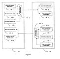
- Figure 4 shows the structure of a system for detecting and reporting faults of data transmission equipment in which the fault causes (power failure) are transmitted through a normal data transmitting/receiving port according to an embodiment of the present invention.
- both the local data transmission equipment 402 and the peer data transmission equipment 404 include normal data transmitting circuits 402-8 and 404-8 as well as normal data receiving data 402-10 and 404-10.
- both the local data transmission equipment and the peer data transmission equipment must have power failure detecting circuits 402-2 and 404-2, which are adapted to detect the fall of supply voltage.
- the fall of supply voltage serves as a basis for judging imminent power failure of the network equipment.
- Circuits (or software) 402-4 and 404-4 adapted to send messages must be available.
- Circuits (or software) 402-6 and 404-6 adapted to receive and identify power failure messages (power failure detection) must be available.
- the power failure detecting circuit detects voltage fall, it indicates that the network equipment is about to incur power failure, and the message sending circuit (or software) can send important state information of the equipment quickly.
- Messages are sent to the peer network equipment, converted by the peer network equipment, and then sent to the NMS.
- the message sent upon power failure is not sent to the NMS directly, so the channel for transmitting the message can be selected flexibly, without being limited to the dedicated Operation Administration and Maintenance (OAM) channel (for example, in the case of transmitting SOH bytes of the equipment in a multi-service transfer platform).
- OAM Operation Administration and Maintenance
- the message can also be put into the payload for transmitting.
- the message sending circuit can keep working normally by using the energy conservation component, but not limited to the standby power supply, of the equipment.
- the ports for sending and receiving messages include, but are not limited to, the normal data sending and receiving port, and may be a dedicated port, which is exclusively adapted to send and receive power failure messages.
- Power failure messages may be specific bit sequences, codes or data packets. Such specific bit sequences, codes and data packets have distinct features, and are easily detectible by the message detecting circuit or software. Power failure messages should be different from normally transmitted data so that the detecting circuit will not mistakenly regard the normally transmitted data as power failure messages.
- Reported messages are not limited to power failure messages, and may be important state messages of other equipment.
- the transmission process may be the circumstance in Figure 4 , in which the data port for sending/receiving power failure messages is the same as the data port for sending/receiving normal data, or the circumstance in Figure 5 , in which a dedicated port is used for sending/receiving power failure messages.
- the transmission process is not limited to the previous two circumstances.
- Figure 5 shows the structure of a system for detecting and reporting faults of data transmission equipment in which the fault causes (power failure) are transmitted through a dedicated port according to an embodiment of the present invention.
- the power failure message sending circuit sends the power failure message through a dedicated port to the power failure message detecting circuit of the peer data transmission equipment 404 directly.
- the power failure message sending circuit sends a power failure message through a dedicated port to the power failure detecting circuit of the local data transmission equipment directly.
- Figure 6 shows the time sequence from detecting voltage fall to main voltage failure of the system according to an embodiment of the present invention.
- Figure 6 is an example of time sequence of the MSTP equipment from detecting voltage fall to main voltage failure of the system in the process of detecting and reporting power failure on MSTP equipment.
- the waveform in Figure 6 is the working voltage of the power failure message sending circuit, and the following waveform is the power failure signal output by the power failure detecting circuit, where low levels are effective.
- the time interval from the event that the power failure detecting circuit outputs an effective power failure signal to the event that the working voltage of the message sending circuit begins falling is only about 1.5 ms. Namely, for the specific equipment, the power failure message must be sent out within 1.5 ms.
- the power supply used by the chip on a board is generally 1.2 V ⁇ 3.3 V, and the power failure detection may be performed at the input 220 VAC/110 VAC or -48 VDC/24 VDC side. If the power supply is backed up in a 1+1 backup mode, the power failure detection is preferably performed at the place where the power supply is closed. In this way, the power failure detecting circuit detects the power failure of the equipment rather than the power failure of the input power supply.
- the power failure message may be put into the specific byte of the SOH such as DCC byte (D1 ⁇ D12) for transmitting. After power failure is detected, the specific byte begins to send special bit sequences such as PRBS.
- the length of a special bit sequence should be greater than 32 bits. If a PRBS is selected for transmitting power failure messages, the selected PRBS should be different from the PRBS of ordinary instruments. In this way, the power failure message receiving circuit will not mistakenly detect the power failure message during a test performed through an instrument.
- the power failure message receiving circuit detects special bit sequences, and reports NE power failure to the peer side after detecting a special bit sequence.
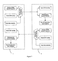
- Figure 7 shows the structure of a system for detecting and reporting faults of data transmission equipment in an Ethernet according to an embodiment of the present invention.
- the power failure detecting circuit of NE1 detects whether the power supply of NE1 fails. If the detection result indicates power failure, the message sending and selecting circuit selects to send a PRBS/special bit sequence, and sends out the PRBS/special bit sequence completely before the sending circuit fails.
- the detecting circuit of NE2 detects the PRBS/special bit sequence, and outputs the power failure alarm of NE1 to the NMS after detecting a PRBS/special bit sequence.
- the power failure detecting circuit of NE2 detects whether the power supply of NE2 fails. If the detection result indicates power failure, the message sending and selecting circuit selects to send a PRBS/special bit sequence, and sends out the PRBS/special bit sequence completely before the sending circuit fails.
- the detecting circuit of NE1 detects the PRBS/special bit sequence, and outputs the power failure alarm of NE2 to the NMS after detecting a PRBS/special bit sequence.
- the message that needs to be reported at the time of power failure can be encapsulated into an Ethernet packet as part of the OAM information.
- the maintainers can obtain the information about power failure of the peer communication equipment without any auxiliary communication means.
- the maintainers can additionally know whether the service interruption is caused by power failure.
- the communication equipment is more maintainable.
- the message sent in the case of power failure is not reported to the NMS directly, but is sent to the peer equipment; and then the peer equipment reports the message to the NMS, which speeds up the reporting.
- the channel of transmitting messages can be selected at discretion.
- NMS messages for example, transmitting DCC bytes of the MSTP equipment
- data link previously used for data transmission for example, transmitting various payloads of the MSTP equipment such as VC4, VC3, and VC12.
Landscapes
- Engineering & Computer Science (AREA)
- Computer Networks & Wireless Communication (AREA)
- Signal Processing (AREA)
- Maintenance And Management Of Digital Transmission (AREA)
- Small-Scale Networks (AREA)
- Data Exchanges In Wide-Area Networks (AREA)
Claims (13)
- Verfahren zum Erkennen und Melden von Fehlern von Datenübertragungsgeräten, wobei ein lokales Datenübertragungsgerät (102, 402) Fehlerursachen des lokalen Datenübertragungsgeräts (102, 402) erkennt,
wobei das Verfahren die folgenden Schritte umfasst:Senden der erkannten Fehlerursachen und wichtiger Zustandsinformationen des lokalen Datenübertragungsgeräts (102, 402) durch das lokale Datenübertragungsgerät (102, 402) zu einem Peer-Datenübertragungsgerät (104, 404);wobei das Verfahren durch die folgenden Schritte gekennzeichnet ist:Senden der erkannten Fehlerursachen und der wichtigen Zustandsinformationen des lokalen Datenübertragungsgeräts (102, 402) durch das lokale Datenübertragungsgerät (102, 402) zu dem Peer-Datenübertragungsgerät (104, 404) beim Erkennen eines Spannungsabfalls vor dem Ausfall der normalen Arbeitsweise des lokalen Datenübertragungsgeräts (102, 402); wobei das Senden der erkannten Fehlerursachen und der wichtigen Zustandsinformationen des lokalen Datenübertragungsgeräts zu dem Peer-Datenübertragungsgerät ferner Folgendes umfasst: Hinzufügen der Fehlerursachen und wichtigen Zustandsinformationen zu den Nutzinformationen, die zu dem Peer-Datenübertragungsgerät gesendet werden; und
Identifizieren der empfangenen Fehlerursachen und der wichtigen Zustandsinformationen durch das Peer-Datenübertragungsgerät (104, 404) und Melden der identifizierten Fehlerursachen und der wichtigen Zustandsinformationen des lokalen Datenübertragungsgeräts (102, 402) durch das Peer-Datenübertragungsgerät (104, 404) an ein Netzwerkverwaltungssystem NMS. - Verfahren nach Anspruch 1, wobei die erkannten Fehlerursachen und die wichtigen Zustandsinformationen des lokalen Datenübertragungsgeräts vollständig zu dem Peer-Datenübertragungsgerät gesendet werden.
- Verfahren nach Anspruch 1 oder 2, wobei die Prozedur des Sendens der erkannten Fehlerursachen und der wichtigen Zustandsinformationen des lokalen Datenübertragungsgeräts zu dem Peer-Datenübertragungsgerät Folgendes umfasst:Senden von Fehlerursachen und wichtigen Zustandsinformationen zu dem allgemeinen Datenempfangsport und/oder dedizierten Datenempfangsport des Peer-Datenübertragungsgeräts durch einen allgemeinen Datensendeport und/oder dedizierten Datensendeport des Kanals der Operation Administration and Maintenance OAM des lokalen Datenübertragungsgeräts.
- Verfahren nach einem der Ansprüche 1 bis 3, ferner mit dem folgenden Schritt:Erkennen, ob die Spannung der Hauptstromversorgung und/oder internen Stromversorgung des lokalen Datenübertragungsgeräts abfällt, wobei, wenn ein Spannungsabfall erkannt wird, er anzeigt, dass ein Ausfall der Stromversorgung des Netzwerkgeräts bevorsteht.
- Verfahren nach Anspruch 1 oder 4, ferner mit dem folgenden Schritt:Erkennen, ob die Spannung der Hauptstromversorgung und/oder internen Stromversorgung des lokalen Datenübertragungsgeräts abfällt, wobei, wenn die Spannung abfällt, die Fehlerursache ein Ausfall der Stromversorgung des lokalen Datenübertragungsgeräts ist.
- Datenübertragungsgerät (102, 402) mit einem Fehlerursachen-Erkennungsmodul (102-6, 104-6, 402-6), das dafür ausgelegt ist, die Fehlerursachen des Datenübertragungsgeräts (102, 402) zu erkennen;
wobei das Gerät (102, 402) Folgendes umfasst:ein Fehlerursachen-Sendemodul (102-8, 104-8, 402-4), das dafür ausgelegt ist, die erkannten Fehlerursachen und die wichtigen Zustandsinformationen des Datenübertragungsgeräts zu einem Peer-Datenübertragungsgerät (104, 404) zu senden;wobei das Gerät durch Folgendes gekennzeichnet ist:wenn das Fehlerursachen-Erkennungsmodul (102-6, 104-6, 402-6) einen Spannungsabfall erkennt, ist das Fehlerursachen-Sendemodul (102-8, 104-8, 402-4) ferner dafür ausgelegt, die erkannten Fehlerursachen und die wichtigen Zustandsinformationen des Datenübertragungsgeräts (102, 402) vor dem Ausfall der normalen Arbeitsweise des Datenübertragungsgeräts (102, 402) zu dem Peer-Datenübertragungsgerät (104, 404) zu senden; und wobei
die Eingangsseite des Fehlerursachen-Sendemoduls ferner die zu dem Peer-Datenübertragungsgerät übertragenen Nutzinformationen eingibt und das Fehlerursachen-Sendemodul die Fehlerursachen und wichtigen Zustandsinformationen zu den Nutzinformationen hinzufügt, die zu dem Peer-Datenübertragungsgerät gesendet werden. - Datenübertragungsgerät nach Anspruch 6, ferner mit einer Sendestromversorgung, die dafür ausgelegt ist, das Fehlerursachen-Sendemodul mit Strom zu versorgen, um die normale Arbeitsweise aufrechtzuerhalten, wobei, wenn das Fehlerursachen-Erkennungsmodul einen Spannungsabfall erkennt, das Fehlerursachen-Sendemodul die Fehlerursachen und die wichtigen Zustandsinformationen heraussendet, bevor die Sendestromversorgung mit der Stromversorgung aufhört.
- Datenübertragungsgerät nach Anspruch 7, wobei die Sendestromversorgung eine Energieerhaltungskomponente und/oder eine Standby-Stromversorgung des Datenübertragungsgeräts umfasst.
- Datenübertragungsgerät nach Anspruch 7, wobei das Fehlerursachen-Erkennungsmodul ferner Folgendes umfasst:eine Eingabeeinheit, die dafür ausgelegt ist, durch Verbindung mit der Hauptstromversorgung und/oder internen Stromversorgung des Datenübertragungsgeräts die Spannung der Hauptstromversorgung und/oder internen Stromversorgung auszugeben; undeine Beurteilungseinheit, die dafür ausgelegt ist, die Informationen, die anzeigen, dass die Fehlerursache Ausfall der Stromversorgung des Datenübertragungsgeräts ist, auszugeben, wenn die Spannung der Hauptstromversorgung und/oder internen Stromversorgung abfällt.
- Datenübertragungsgerät nach Anspruch 7, wobei die Ausgangsseite des Fehlerursachen-Sendemoduls mit einem Kanal der Operation Administration and Maintenance OAM, dem allgemeinen Datensendeport und/oder dem dedizierten Datensendeport des Datenübertragungsgeräts verbunden ist.
- System zum Erkennen und Melden von Fehlern von Datenübertragungsgeräten mit einem lokalen Datenübertragungsgerät nach einem der Ansprüche 6-10,
dadurch gekennzeichnet, dass das System ferner Folgendes umfasst:ein Peer-Datenübertragungsgerät (104, 404), das dafür ausgelegt ist, die empfangenen Fehlerursachen und die wichtigen Zustandsinformationen des lokalen Datenübertragungsgeräts (102, 402) zu identifizieren und diese an ein Netzwerkverwaltungssystem NMS zu melden. - System nach Anspruch 11, wobei das zweite Datenübertragungsgerät ferner Folgendes umfasst:eine Peer-Fehlerursachen-Identifizierungseinheit (104-10), die dafür ausgelegt ist, die empfangenen Fehlerursachen und wichtigen Zustandsinformationen des Peer-Datenübertragungsgeräts (104, 404) zu identifizieren; undeine Meldeeinheit (104-10), die dafür ausgelegt ist, die identifizierten Fehlerursachen und wichtigen Zustandsinformationen des Peer-Datenübertragungsgeräts (104, 404) an das NMS zu melden.
- System nach Anspruch 12, wobei die Eingangsseite der Peer-Fehlerursachen-Identifizierungseinheit mit dem allgemeinen Datenempfangsport und/oder dem dedizierten Datenempfangsport des ersten Datenübertragungsgeräts (102, 402) verbunden ist.
Applications Claiming Priority (2)
| Application Number | Priority Date | Filing Date | Title |
|---|---|---|---|
| CNA2006100674090A CN1852171A (zh) | 2006-03-27 | 2006-03-27 | 数据传输设备及其故障检测和上报方法 |
| PCT/CN2007/000990 WO2007109998A1 (en) | 2006-03-27 | 2007-03-27 | A method and a system for detecting and reporting the failure of the data transmission device |
Publications (3)
| Publication Number | Publication Date |
|---|---|
| EP2015512A1 EP2015512A1 (de) | 2009-01-14 |
| EP2015512A4 EP2015512A4 (de) | 2009-04-22 |
| EP2015512B1 true EP2015512B1 (de) | 2010-07-07 |
Family
ID=37133641
Family Applications (1)
| Application Number | Title | Priority Date | Filing Date |
|---|---|---|---|
| EP07720564A Active EP2015512B1 (de) | 2006-03-27 | 2007-03-27 | Verfahren und system zum erkennen und melden des ausfalls der datenübertragungseinrichtung |
Country Status (6)
| Country | Link |
|---|---|
| US (1) | US20090022058A1 (de) |
| EP (1) | EP2015512B1 (de) |
| CN (1) | CN1852171A (de) |
| AT (1) | ATE473569T1 (de) |
| DE (1) | DE602007007599D1 (de) |
| WO (1) | WO2007109998A1 (de) |
Families Citing this family (11)
| Publication number | Priority date | Publication date | Assignee | Title |
|---|---|---|---|---|
| US8787751B2 (en) | 2009-04-22 | 2014-07-22 | Futurewei Technologies, Inc. | Method for identifying the optical network unit power off reason |
| CN101931549A (zh) * | 2009-06-19 | 2010-12-29 | 中兴通讯股份有限公司 | 基于802.3ah OAM的链路异常的检测方法和装置 |
| CN101882956B (zh) * | 2010-07-08 | 2016-05-11 | 威盛电子股份有限公司 | 数据传输系统和方法 |
| CN102820946B (zh) * | 2011-06-07 | 2017-11-14 | 邳州高新区城市矿产研究院有限公司 | 一种传输设备及其主动发布自身信息的方法 |
| WO2012106890A1 (zh) * | 2011-07-14 | 2012-08-16 | 华为技术有限公司 | 信号处理方法及从设备 |
| CN102307367A (zh) * | 2011-08-18 | 2012-01-04 | 大唐移动通信设备有限公司 | 一种通信设备及掉电告警方法 |
| US8725998B1 (en) | 2011-08-31 | 2014-05-13 | Amazon Technologies, Inc. | Managing host computing devices with a host control component |
| CN107465841B (zh) * | 2017-08-15 | 2022-10-14 | 西藏育宁科技集团有限公司 | 一种故障信息上报方法及终端 |
| CN109862557A (zh) * | 2017-11-30 | 2019-06-07 | 上海华为技术有限公司 | 通道建立方法以及基站 |
| CN112407326B (zh) * | 2020-11-13 | 2022-07-12 | 峰飞航空科技(昆山)有限公司 | 无人机系统故障诊断方法、装置、电子设备和存储介质 |
| CN113449703B (zh) * | 2021-08-31 | 2021-11-23 | 天津联图科技有限公司 | 环境在线监测数据的质控方法、装置、存储介质及设备 |
Family Cites Families (11)
| Publication number | Priority date | Publication date | Assignee | Title |
|---|---|---|---|---|
| JPS63200699A (ja) * | 1987-02-17 | 1988-08-18 | Fujitsu Ltd | 遠隔保守制御方式 |
| JPH09128015A (ja) * | 1995-11-02 | 1997-05-16 | Omron Corp | Plcのリモートi/oシステム |
| FR2750516B1 (fr) * | 1996-07-01 | 1998-07-31 | Bull Cp8 | Dispositif pour communiquer avec un support de donnees portable |
| US5761084A (en) * | 1996-07-31 | 1998-06-02 | Bay Networks, Inc. | Highly programmable backup power scheme |
| JPH11127220A (ja) * | 1997-10-20 | 1999-05-11 | Fujitsu Ltd | ネットワークシステム及び通信装置 |
| US7106742B1 (en) * | 2000-01-13 | 2006-09-12 | Mercury Computer Systems, Inc. | Method and system for link fabric error detection and message flow control |
| US6816461B1 (en) * | 2000-06-16 | 2004-11-09 | Ciena Corporation | Method of controlling a network element to aggregate alarms and faults of a communications network |
| US7370239B2 (en) * | 2001-05-31 | 2008-05-06 | Fisher-Rosemount Systems, Inc. | Input/output device with configuration, fault isolation and redundant fault assist functionality |
| US8036104B2 (en) * | 2002-07-15 | 2011-10-11 | Qualcomm Incorporated | Methods and apparatus for improving resiliency of communication networks |
| US7213179B2 (en) * | 2002-07-30 | 2007-05-01 | Cisco Technology, Inc. | Automated and embedded software reliability measurement and classification in network elements |
| TWI248567B (en) * | 2004-09-08 | 2006-02-01 | Delta Electronics Inc | Uninterruptible power supply with network hub functions |
-
2006
- 2006-03-27 CN CNA2006100674090A patent/CN1852171A/zh active Pending
-
2007
- 2007-03-27 EP EP07720564A patent/EP2015512B1/de active Active
- 2007-03-27 DE DE602007007599T patent/DE602007007599D1/de active Active
- 2007-03-27 WO PCT/CN2007/000990 patent/WO2007109998A1/zh not_active Ceased
- 2007-03-27 AT AT07720564T patent/ATE473569T1/de not_active IP Right Cessation
-
2008
- 2008-09-26 US US12/239,349 patent/US20090022058A1/en not_active Abandoned
Also Published As
| Publication number | Publication date |
|---|---|
| WO2007109998A1 (en) | 2007-10-04 |
| DE602007007599D1 (de) | 2010-08-19 |
| EP2015512A4 (de) | 2009-04-22 |
| EP2015512A1 (de) | 2009-01-14 |
| CN1852171A (zh) | 2006-10-25 |
| US20090022058A1 (en) | 2009-01-22 |
| ATE473569T1 (de) | 2010-07-15 |
Similar Documents
| Publication | Publication Date | Title |
|---|---|---|
| EP2015512A1 (de) | Verfahren und system zum erkennen und melden des ausfalls der datenübertragungseinrichtung | |
| CN102437922B (zh) | 一种基于n-1原则的电力通信网业务影响分析方法 | |
| CN101232384B (zh) | 一种以太网供电功能交换机的测试方法及装置 | |
| CN106130627A (zh) | 光接入网故障段落定位方法和系统 | |
| CN101820558A (zh) | 一种无源光网络检测长发光onu的方法 | |
| WO2015158178A1 (zh) | 一种otn保护倒换自动化测试系统、方法及装置 | |
| CN101499820A (zh) | 业务传输的保护方法和网络设备 | |
| US20100128611A1 (en) | Transmitting apparatus, alarm control method, and computer product | |
| CN108650140A (zh) | 光传输设备业务故障的自动化辅助分析方法和系统 | |
| CN100450251C (zh) | 基站故障检测方法及故障检测系统 | |
| US7719992B1 (en) | System for proactive time domain reflectometry | |
| CN204515115U (zh) | 故障指示器测试治具 | |
| CN116866157B (zh) | 一种基于5g纵联差动保护的数据传输方法 | |
| CN119182711B (zh) | E1路由保护倒换设备 | |
| CN103995216B (zh) | 电力系统线路故障自动监测方法 | |
| CN108123752A (zh) | 一种基于地理信息定位的epon精确环路检测方法 | |
| CN115622606B (zh) | 故障检测电路、仪器、方法、装置、系统、设备及介质 | |
| US7190666B1 (en) | Identification of priority faults in a transport network | |
| CN112436976B (zh) | 一种集成式数据综合测试仪及其使用方法 | |
| CN117201288A (zh) | 集客专线故障根因定位方法、装置、电子设备及存储介质 | |
| CN100502266C (zh) | 通信设备交流电源失效告警上报的方法 | |
| CN101610166B (zh) | 一种中间节点、级联保护系统及级联保护方法 | |
| CN107040309B (zh) | 一种基于物理层的光纤通信断链快速监测方法 | |
| CN220711490U (zh) | 一种光纤通断及节点环境实时监测装置 | |
| CN218633984U (zh) | 网络监测分析记录仪 |
Legal Events
| Date | Code | Title | Description |
|---|---|---|---|
| PUAI | Public reference made under article 153(3) epc to a published international application that has entered the european phase |
Free format text: ORIGINAL CODE: 0009012 |
|
| 17P | Request for examination filed |
Effective date: 20081010 |
|
| AK | Designated contracting states |
Kind code of ref document: A1 Designated state(s): AT BE BG CH CY CZ DE DK EE ES FI FR GB GR HU IE IS IT LI LT LU LV MC MT NL PL PT RO SE SI SK TR |
|
| AX | Request for extension of the european patent |
Extension state: AL BA HR MK RS |
|
| A4 | Supplementary search report drawn up and despatched |
Effective date: 20090319 |
|
| 17Q | First examination report despatched |
Effective date: 20091211 |
|
| GRAP | Despatch of communication of intention to grant a patent |
Free format text: ORIGINAL CODE: EPIDOSNIGR1 |
|
| GRAS | Grant fee paid |
Free format text: ORIGINAL CODE: EPIDOSNIGR3 |
|
| GRAA | (expected) grant |
Free format text: ORIGINAL CODE: 0009210 |
|
| AK | Designated contracting states |
Kind code of ref document: B1 Designated state(s): AT BE BG CH CY CZ DE DK EE ES FI FR GB GR HU IE IS IT LI LT LU LV MC MT NL PL PT RO SE SI SK TR |
|
| REG | Reference to a national code |
Ref country code: GB Ref legal event code: FG4D |
|
| REG | Reference to a national code |
Ref country code: CH Ref legal event code: EP |
|
| REG | Reference to a national code |
Ref country code: IE Ref legal event code: FG4D |
|
| REF | Corresponds to: |
Ref document number: 602007007599 Country of ref document: DE Date of ref document: 20100819 Kind code of ref document: P |
|
| REG | Reference to a national code |
Ref country code: NL Ref legal event code: T3 |
|
| PG25 | Lapsed in a contracting state [announced via postgrant information from national office to epo] |
Ref country code: SI Free format text: LAPSE BECAUSE OF FAILURE TO SUBMIT A TRANSLATION OF THE DESCRIPTION OR TO PAY THE FEE WITHIN THE PRESCRIBED TIME-LIMIT Effective date: 20100707 |
|
| LTIE | Lt: invalidation of european patent or patent extension |
Effective date: 20100707 |
|
| PG25 | Lapsed in a contracting state [announced via postgrant information from national office to epo] |
Ref country code: LT Free format text: LAPSE BECAUSE OF FAILURE TO SUBMIT A TRANSLATION OF THE DESCRIPTION OR TO PAY THE FEE WITHIN THE PRESCRIBED TIME-LIMIT Effective date: 20100707 Ref country code: AT Free format text: LAPSE BECAUSE OF FAILURE TO SUBMIT A TRANSLATION OF THE DESCRIPTION OR TO PAY THE FEE WITHIN THE PRESCRIBED TIME-LIMIT Effective date: 20100707 Ref country code: FI Free format text: LAPSE BECAUSE OF FAILURE TO SUBMIT A TRANSLATION OF THE DESCRIPTION OR TO PAY THE FEE WITHIN THE PRESCRIBED TIME-LIMIT Effective date: 20100707 |
|
| PG25 | Lapsed in a contracting state [announced via postgrant information from national office to epo] |
Ref country code: CY Free format text: LAPSE BECAUSE OF FAILURE TO SUBMIT A TRANSLATION OF THE DESCRIPTION OR TO PAY THE FEE WITHIN THE PRESCRIBED TIME-LIMIT Effective date: 20100707 Ref country code: BG Free format text: LAPSE BECAUSE OF FAILURE TO SUBMIT A TRANSLATION OF THE DESCRIPTION OR TO PAY THE FEE WITHIN THE PRESCRIBED TIME-LIMIT Effective date: 20101007 Ref country code: PT Free format text: LAPSE BECAUSE OF FAILURE TO SUBMIT A TRANSLATION OF THE DESCRIPTION OR TO PAY THE FEE WITHIN THE PRESCRIBED TIME-LIMIT Effective date: 20101108 Ref country code: PL Free format text: LAPSE BECAUSE OF FAILURE TO SUBMIT A TRANSLATION OF THE DESCRIPTION OR TO PAY THE FEE WITHIN THE PRESCRIBED TIME-LIMIT Effective date: 20100707 Ref country code: IS Free format text: LAPSE BECAUSE OF FAILURE TO SUBMIT A TRANSLATION OF THE DESCRIPTION OR TO PAY THE FEE WITHIN THE PRESCRIBED TIME-LIMIT Effective date: 20101107 |
|
| PG25 | Lapsed in a contracting state [announced via postgrant information from national office to epo] |
Ref country code: GR Free format text: LAPSE BECAUSE OF FAILURE TO SUBMIT A TRANSLATION OF THE DESCRIPTION OR TO PAY THE FEE WITHIN THE PRESCRIBED TIME-LIMIT Effective date: 20101008 Ref country code: SE Free format text: LAPSE BECAUSE OF FAILURE TO SUBMIT A TRANSLATION OF THE DESCRIPTION OR TO PAY THE FEE WITHIN THE PRESCRIBED TIME-LIMIT Effective date: 20100707 Ref country code: BE Free format text: LAPSE BECAUSE OF FAILURE TO SUBMIT A TRANSLATION OF THE DESCRIPTION OR TO PAY THE FEE WITHIN THE PRESCRIBED TIME-LIMIT Effective date: 20100707 Ref country code: LV Free format text: LAPSE BECAUSE OF FAILURE TO SUBMIT A TRANSLATION OF THE DESCRIPTION OR TO PAY THE FEE WITHIN THE PRESCRIBED TIME-LIMIT Effective date: 20100707 |
|
| PG25 | Lapsed in a contracting state [announced via postgrant information from national office to epo] |
Ref country code: DK Free format text: LAPSE BECAUSE OF FAILURE TO SUBMIT A TRANSLATION OF THE DESCRIPTION OR TO PAY THE FEE WITHIN THE PRESCRIBED TIME-LIMIT Effective date: 20100707 |
|
| PLBE | No opposition filed within time limit |
Free format text: ORIGINAL CODE: 0009261 |
|
| STAA | Information on the status of an ep patent application or granted ep patent |
Free format text: STATUS: NO OPPOSITION FILED WITHIN TIME LIMIT |
|
| PG25 | Lapsed in a contracting state [announced via postgrant information from national office to epo] |
Ref country code: EE Free format text: LAPSE BECAUSE OF FAILURE TO SUBMIT A TRANSLATION OF THE DESCRIPTION OR TO PAY THE FEE WITHIN THE PRESCRIBED TIME-LIMIT Effective date: 20100707 Ref country code: IT Free format text: LAPSE BECAUSE OF FAILURE TO SUBMIT A TRANSLATION OF THE DESCRIPTION OR TO PAY THE FEE WITHIN THE PRESCRIBED TIME-LIMIT Effective date: 20100707 Ref country code: RO Free format text: LAPSE BECAUSE OF FAILURE TO SUBMIT A TRANSLATION OF THE DESCRIPTION OR TO PAY THE FEE WITHIN THE PRESCRIBED TIME-LIMIT Effective date: 20100707 Ref country code: SK Free format text: LAPSE BECAUSE OF FAILURE TO SUBMIT A TRANSLATION OF THE DESCRIPTION OR TO PAY THE FEE WITHIN THE PRESCRIBED TIME-LIMIT Effective date: 20100707 Ref country code: CZ Free format text: LAPSE BECAUSE OF FAILURE TO SUBMIT A TRANSLATION OF THE DESCRIPTION OR TO PAY THE FEE WITHIN THE PRESCRIBED TIME-LIMIT Effective date: 20100707 |
|
| 26N | No opposition filed |
Effective date: 20110408 |
|
| PG25 | Lapsed in a contracting state [announced via postgrant information from national office to epo] |
Ref country code: ES Free format text: LAPSE BECAUSE OF FAILURE TO SUBMIT A TRANSLATION OF THE DESCRIPTION OR TO PAY THE FEE WITHIN THE PRESCRIBED TIME-LIMIT Effective date: 20101018 |
|
| REG | Reference to a national code |
Ref country code: DE Ref legal event code: R097 Ref document number: 602007007599 Country of ref document: DE Effective date: 20110408 |
|
| PG25 | Lapsed in a contracting state [announced via postgrant information from national office to epo] |
Ref country code: MC Free format text: LAPSE BECAUSE OF NON-PAYMENT OF DUE FEES Effective date: 20110331 |
|
| REG | Reference to a national code |
Ref country code: CH Ref legal event code: PL |
|
| PG25 | Lapsed in a contracting state [announced via postgrant information from national office to epo] |
Ref country code: MT Free format text: LAPSE BECAUSE OF FAILURE TO SUBMIT A TRANSLATION OF THE DESCRIPTION OR TO PAY THE FEE WITHIN THE PRESCRIBED TIME-LIMIT Effective date: 20100707 |
|
| REG | Reference to a national code |
Ref country code: IE Ref legal event code: MM4A |
|
| PG25 | Lapsed in a contracting state [announced via postgrant information from national office to epo] |
Ref country code: LI Free format text: LAPSE BECAUSE OF NON-PAYMENT OF DUE FEES Effective date: 20110331 Ref country code: CH Free format text: LAPSE BECAUSE OF NON-PAYMENT OF DUE FEES Effective date: 20110331 Ref country code: IE Free format text: LAPSE BECAUSE OF NON-PAYMENT OF DUE FEES Effective date: 20110327 |
|
| PG25 | Lapsed in a contracting state [announced via postgrant information from national office to epo] |
Ref country code: LU Free format text: LAPSE BECAUSE OF NON-PAYMENT OF DUE FEES Effective date: 20110327 |
|
| PG25 | Lapsed in a contracting state [announced via postgrant information from national office to epo] |
Ref country code: TR Free format text: LAPSE BECAUSE OF FAILURE TO SUBMIT A TRANSLATION OF THE DESCRIPTION OR TO PAY THE FEE WITHIN THE PRESCRIBED TIME-LIMIT Effective date: 20100707 |
|
| PG25 | Lapsed in a contracting state [announced via postgrant information from national office to epo] |
Ref country code: HU Free format text: LAPSE BECAUSE OF FAILURE TO SUBMIT A TRANSLATION OF THE DESCRIPTION OR TO PAY THE FEE WITHIN THE PRESCRIBED TIME-LIMIT Effective date: 20100707 |
|
| REG | Reference to a national code |
Ref country code: FR Ref legal event code: PLFP Year of fee payment: 10 |
|
| REG | Reference to a national code |
Ref country code: FR Ref legal event code: PLFP Year of fee payment: 11 |
|
| REG | Reference to a national code |
Ref country code: FR Ref legal event code: PLFP Year of fee payment: 12 |
|
| REG | Reference to a national code |
Ref country code: DE Ref legal event code: R079 Ref document number: 602007007599 Country of ref document: DE Free format text: PREVIOUS MAIN CLASS: H04L0012260000 Ipc: H04L0043000000 |
|
| PGFP | Annual fee paid to national office [announced via postgrant information from national office to epo] |
Ref country code: NL Payment date: 20250217 Year of fee payment: 19 |
|
| PGFP | Annual fee paid to national office [announced via postgrant information from national office to epo] |
Ref country code: DE Payment date: 20250204 Year of fee payment: 19 |
|
| PGFP | Annual fee paid to national office [announced via postgrant information from national office to epo] |
Ref country code: FR Payment date: 20250210 Year of fee payment: 19 |
|
| PGFP | Annual fee paid to national office [announced via postgrant information from national office to epo] |
Ref country code: GB Payment date: 20250206 Year of fee payment: 19 |