EP2015521B1 - NTU-Warteschlangensystem - Google Patents
NTU-Warteschlangensystem Download PDFInfo
- Publication number
- EP2015521B1 EP2015521B1 EP07013474A EP07013474A EP2015521B1 EP 2015521 B1 EP2015521 B1 EP 2015521B1 EP 07013474 A EP07013474 A EP 07013474A EP 07013474 A EP07013474 A EP 07013474A EP 2015521 B1 EP2015521 B1 EP 2015521B1
- Authority
- EP
- European Patent Office
- Prior art keywords
- frame
- segment
- data
- segments
- frames
- Prior art date
- Legal status (The legal status is an assumption and is not a legal conclusion. Google has not performed a legal analysis and makes no representation as to the accuracy of the status listed.)
- Active
Links
Images


Classifications
-
- H—ELECTRICITY
- H04—ELECTRIC COMMUNICATION TECHNIQUE
- H04L—TRANSMISSION OF DIGITAL INFORMATION, e.g. TELEGRAPHIC COMMUNICATION
- H04L49/00—Packet switching elements
- H04L49/90—Buffering arrangements
- H04L49/9036—Common buffer combined with individual queues
-
- H—ELECTRICITY
- H04—ELECTRIC COMMUNICATION TECHNIQUE
- H04L—TRANSMISSION OF DIGITAL INFORMATION, e.g. TELEGRAPHIC COMMUNICATION
- H04L49/00—Packet switching elements
- H04L49/90—Buffering arrangements
-
- H—ELECTRICITY
- H04—ELECTRIC COMMUNICATION TECHNIQUE
- H04L—TRANSMISSION OF DIGITAL INFORMATION, e.g. TELEGRAPHIC COMMUNICATION
- H04L49/00—Packet switching elements
- H04L49/90—Buffering arrangements
- H04L49/9021—Plurality of buffers per packet
Definitions
- the present invention relates to a method and a queuing system for storing frames or other packets of data in queues in a bulk storage device (for example a bank of one or more SDRAMs) that can only be accessed efficiently in large fixed size chunks.
- a bulk storage device for example a bank of one or more SDRAMs
- a bulk storage device e.g. synchronous dynamic RAM (SDRAM)
- SDRAM synchronous dynamic RAM
- frames may be arriving interleaved from different flows at one time destined for the one queue.
- the SDRAM In a network termination equipment (NTE), for example, the SDRAM is used inefficiently and it can waste up to half the available bandwidth.
- NTE network termination equipment
- a method for storing frames or packets of data in queues in a bulk storage device is described in US 2006/0187963 A1 .
- This method comprises the steps of: splitting up at least a portion of the bulk storage device into a number of buffers each of one or more chunks and queuing the frames or other packets of data which arrive from an input pipe as a series of segments, wherein a frame or other packet of data may be split into one or more segments.
- a format is found that packs frames into fixed-size buffers in a bulk storage device, e.g. SDRAM, but that allows frames or other packets of data to be added to the queue only when complete.
- a bulk storage device e.g. SDRAM
- the bulk storage device or a portion thereof used for queuing, is split up into a number of buffers each of one or more chunks.
- Frames arrive for queuing from an input pipe as a series of segments.
- a frame may be split into one or more segments, but if it is split into multiple segments then each segment except the last will fill a buffer when it has a link label attached to it.
- the link label is described below and serves to link segments into queues within the bulk storage.
- the size of the last segment is such when a link label is attached, it will fit within one buffer but need not fill it.
- a key feature of this queuing method is to pack these final segments into buffers so that the bulk storage is used efficiently, and further that if the bandwidth available for accessing the bulk storage is limited, then this bandwidth is used efficiently.
- frames from a number of flows may be interleaved at the segment level.
- the pipe comprises a series of complete segments.
- the segments for one frame arrive in order, but there may be intervening segments from other flows.
- the defining characteristic of a flow is that only one frame will be in progress on a flow at any one time.
- a key property of this queuing method is that any flow on the input pipe can write to any queue, in other words a queue is not dedicated to a particular input flow.
- the frame When the last segment of a frame is received, the frame is added to the selected queue.
- the segment has a link label attached and is then stored at the tail end of the queue.
- Each queue is built from a linked list of buffers in the bulk storage device.
- the final segments of frames in this queue are then packed into the buffers.
- a final segment may fit into one buffer or may be split between two consecutive buffers.
- side chain is used for the linked list of buffers containing non-final segments of a frame.
- main chain is used for the linked list of buffers that holds the packed final segments of all the frames in one queue.
- Each buffer in the main chain (except possibly the last) has at least one link label.
- the link field in each link label in a main-chain buffer identifies the next buffer in the chain.
- the queuing system or module provides multiple queues in SDRAM. It supports multiple input flows and allows any input flow to write to any queue.
- the input is a segmented data stream.
- the output is a time division multiplexed (TDM) data stream again supporting multiple flows.
- TDM time division multiplexed
- Each queue will drive a fixed output flow or a fixed set of output flows.
- Sending to multiple flows is designed to support protection modes where frames are sent out on both network ports. The frame will, in general, be written once to SDRAM and read twice.
- This module is specified, for example, for use in the 10/100/1000 Mbit network termination unit (NTU).
- NTU network termination unit
- the queue format is combined with sharing of a local storage, particularly the internal BlockRAM, by the two directions and the bypassing of the SDRAM when the queue is small.
- SOF Start Of Frame, and is the first segment of a multi-segment frame.
- MOF Middle Of Frame, and is a middle segment of a frame of three or more segments.
- EOF End Of Frame, and is the final segment of a multi-segment frame.
- CF is Complete Frame, and is a whole frame fitting in one segment.
- B is the Base field of the link label used to attach a side chain to an EOF segment.
- L is the Link field of the link label used to link together a single chain.
- the link label also has additional fields not shown in this diagram according to Fig. 1 , such as a field for the length of an EOF or CF segment, a field for a counter to tell the length of the side chains etc.
- the first frame is shown in Fig. 1 (on top and at the bottom left side) and has a side chain of two segments.
- the first one 1 is a start of frame segment (SOF) and the second one 2 is a middle of frame segment (MOF).
- the EOF segment 3 is in the main chain.
- the EOF segment has had padding added to ensure that the next link label is aligned correctly.
- the second frame in the middle of Fog. 1 has one start of frame segment 4 in the main chain and one end of frame segment 5 in the main chain. Again padding has been added to align the start of the next frame.
- the third frame in Fig. 1 (bottom right side) comprises just a complete frame segment 6 in the main chain and has no side chain. It is shown with no padding, but padding would be added if required.
- the head and tail pointers to each queue can be implemented in any way that the controlling engine wishes. It is not envisaged that they are stored in the bulk storage device but rather in some local storage.
- the final link in each chain is not null but points to a pre-allocated next buffer.
- the controlling engine will always pre-allocate the next buffer. This leads to wasting one buffer per flow for a pre-allocated side-chain buffer, and one buffer per queue for a pre-allocated main-chain buffer.
- the purpose is that as a segment is received and a buffer is filled then the buffer can be written out to the bulk storage device immediately and it is not necessary to hold so much data locally.
- a final segment When a final segment is received, it may fill a buffer, in which case that buffer may be written out immediately. Otherwise, one will be left with a partially filled buffer at the tail of the queue, this must be stored locally until such time as it is filled. This leads to a storage requirement of at least two buffers per queue in the controlling engine.
- One buffer is for a partially filled buffer at the tail waiting to be written to the bulk storage and one for a partially read buffer at the head waiting for the next frame to be sent on the output pipe.
- the end of a chain must be determined by another mechanism.
- the end of the main chain is determined by the tail pointer.
- the end of the side chain is determined by having a side-chain length counter in the link label of the final segment.
- a queue When a queue starts up or is empty, it will have just one buffer in use and a second one pre-allocated.
- the head and tail pointers will both point to the same place and so the buffer is empty.
- the first frame When the first frame is added, it may not fill the buffer and would then not be written out to the bulk storage device. Nevertheless the tail pointer will be updated and so the queue is non-empty and the frame may be output.
- the head pointer will be advanced, and the frame can be output without any accesses, read or write, made to the bulk storage device.
- the amount of local storage needed is likely to depend strongly on the delay requirements of the system. If you just have the two buffers as described above, then there is little pre-fetching of data. All data in the side chains always has to be read from the bulk storage and this is only started once that frame has been selected as the next frame for transmission.
- the buffer size may exceed the chunk size, which defines the size of reads and writes to the bulk storage. If this happens, then one may write out filled chunks within a partially filled buffer or read in completed chunks from an incomplete buffer. This will save local storage, but will increase the complexity of the controlling engine. As a minimum, now only two chunks of local storage per queue are needed rather than two buffers.
- the device is being used in a Gigabit Ethernet MAC Relay, where bulk storage is provided by DDR SDRAMs as a low cost bulk memory device outside a field programmable gate array (FPGA).
- FPGA field programmable gate array
- An FPGA provides the controlling engine with local buffers provided by dual-port SRAM blocks.
- One port interfaces to the external SDRAM and the other to the input and output pipes.
- the chunk size is 128 bytes, that is 16 bytes to each of the four banks per device.
- the buffer size is made to be 256 bytes to keep the overhead down to around 4% worst case.
- the ability for multiple input ports to write to the same queue reduces the number of queues needed in the system, which in turn reduces the amount of buffering needed.
- the queuing system or module has to allocate 256-byte buffers in SDRAM and also, independently, in its main BlockRAM memory in the FPGA. This is very confusing. It is particularly confusing to call both buffers, so instead buffers in SDRAM are called buffers and buffers in BlockRAM are called blocks . So the SDRAM has approximately 256k buffers, and the BlockRAM has some 64 blocks.
- the queuing system shown in Fig. 2 takes in frames from the upstream pipeline and queues them until they can be sent out on the downstream pipeline.
- the queues are large and so use external SDRAM for the bulk of their storage.
- the queuing system is configured by the processor using the register interface.
- the queuing system provides statistics to the statistics module.
- the queuing system supports multiple flows on its input and output. Frames on one flow may interleave frames on another flow, but each flow can only have one frame in progress at a time.
- Fig. 3 shows the main characteristics of queues:
- Multicast queues are only used for protection. They send data to both network ports. Data is written to the queue once and read twice. There is no support for varying the set of ports associated with a multicast queue.
- Queues to a port will be assigned to different priorities. Queues will be statically assigned. Separate queues will not be used for separate services at the same priority. This is an NTE type function.
- a frame comprises one or more segments in a flow.
- the segments of a frame in one flow can be interleaved with the segments of other frames in other flows.
- frames from the upstream ECPA generator will set the source port in the frame to say the front-panel port that is being tested. But the ECPA bit will be set in the pipeline label and this means that the ECPA flow is to be used for this frame.
- An ECPA frame may be interleaved with a normal frame from the same port.
- the processor has its own source port but it can set the source port to one of the front-panel ports if it wants to inject an ESA frame and have it treated like a frame received on a front-panel port.
- the segmented format is used in the upstream pipeline and on the input to the queuing system. This comprises a sequence of segments.
- a strobe identifies the first word of a segment and a length field in the first word indicates how much data follows.
- a similar segmented format is used throughout F-NTE, although the details are different.
- the use is restricted to the upstream pipeline and the input to the queuing system.
- frames are segmented as required by the queuing system and no changes are allowed to the size of the segments before they enter the queuing system. The segmentation is lost on the output of the queuing system.
- the first word of each segment is the pipeline label. This has the size field and serves to associate a segment with a port or other flow, and to allow segments to be grouped into frames.
- the length field in the pipeline label gives the number of following bytes excluding the pipeline label, minus one. The smallest value for this field is zero where an end of frame segment contains only one data byte - presumably the last byte of the CRC. The largest value is 247 saying that the segment contains 248 data bytes. All segments except the final segment of a frame will be filled in NTU.
- the first segment of a frame has an extra label called a command label carrying metadata. This counts as 8 bytes towards the segment data size leaving 240 frame data bytes maximum in the first segment. The 8 bytes of command label are included in the segment size.
- the segments arriving at the queuing system will be aligned with respect to the 62.5 Mbit/s clock so that the pipeline label is received when the 62.5 MHz clock is low. Each subsequent 62.5 MHz clock cycle will deliver another eight bytes of data.
- the segmented data format according to Fig. 4 shows two segments with a gap between the segments.
- the first segment shows the command label present in the first segment of a frame and some padding as might be seen in the last segment of a frame.
- the actual segment is too short to hold a complete frame so these two features are not really compatible.
- the pipeline label is read by the queuing system and converted into the linkage label for use in SDRAM. On output, it is converted into the control bits associated with the various flows.
- the PL_SOP PeLine Label start of packet
- the PL_EOP PeLine Label end of packet
- the 8-bit PL_LEN PeLine Label length
- the 5-bit PL_QID gives the number of the queue in which to store the frame.
- the PL_DROP field says that a frame is to be dropped if non-zero and the value gives the reason for dropping the frame. The frame can be dropped in any segment.
- the 3-bit PL_PORT gives the input port sourcing this frame in the upstream pipe.
- the ECPA module injects a frame, it does so on behalf of a port and so the PL_PORT field will indicate that port. But the ECPA generator generates one flow and so it sets the PL_ECPA bit to say that this frame is in the ECPA flow and segments with the PL_ECPA bit set should be assembled into frames using the ECPA flow and not the flow associated with the PL_PORT field.
- the processor has a single flow. All processor frames have the PL_PROC bit set to indicate that they belong to the processor flow. For management frames the PL_PORT will also indicate the processor flow, and this will stop the frame being processed as a received frame, but ESA frames should be treated as frames input on a user port and so have the PL_PORT field set to indicate a user port, but sets the PL_PROC bit to say that the flow is the processor's flow.
- the queuing system uses these fields to identify the flow associated with each segment and thus to tie segments together into complete frames. It is otherwise not interested in the port number.
- the command label is the first eight bytes of the first segment of each frame. It carries metadata transparently through the queuing system. The command label is not read or modified by this block but is treated as just another part of the data.
- SDRAM holds a number of queues and a number of free buffers. It also holds the free buffer list. At start up the free buffer list holds over 250,000 buffers, which is much more than can be kept track of in BlockRAM.
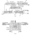
- Each queue comprises a linked list of 256-byte buffers (shown at the bottom the following diagram). The last segment of each frame is stored in these buffers. These are packed, with each frame rounded up to the next multiple of eight bytes. One frame thus uses from 16 to 256 bytes of this queue. The final segment may be contained in one buffer or split between two buffers. The packing of segments into requires that incomplete blocks can be shared between the Put and Get sides and data read out from a shared block without having to be transferred into SDRAM. The non-final segments always fill a complete buffer. These buffers are linked into a list with the base of the list given in the link label of the final segment.
- the main queue is shown at the bottom. It has three frames shown. This is just one of twenty queues implemented in the NTU queuing system.
- the first frame has a side chain of two segments of 248 data bytes each.
- the first is a start of frame segment (SOF) and the second is a middle of frame segment (MOF).
- SOF segment includes the command label (CL) as part of the 248 bytes.
- CL command label
- the link label at the start of each segment is not included in the 248 bytes and builds the total size up to 256 bytes for a side chain buffer.
- the end-of-frame fragment (EOF) has 43 bytes of data. To this, has been added 5 bytes of padding.
- the first frame does not start at the beginning of the first chunk of the main queue. Presumably, there was a previous frame, not shown, that ended at this point.
- the second frame has one 248-byte start of frame segment and then the final segment is 86 bytes, to which is added 2 bytes of padding.
- the third frame is 64 bytes and so uses just 80 bytes in the main queue. It has an 8-byte linkage label with an 8-byte command label added to the data. Note that a frame of 240 bytes or less, excluding the command label, has no chain.
- a maximum length 9250-byte frame has a chain of 37 buffers. If the final segment, including padding, reaches to the last word of a buffer, then a new buffer is allocated at this time and the head or tail pointer will move on to the start of the new buffer. The link to the new buffer will be stored in the old frame.
- the word index within a buffer associated with a head or tail pointer is thus always in the range 0 to 31 (with units of 8 bytes).
- a list of free buffers is stored in the SDRAM. It holds the 18-bit buffer index packed three to an 8-byte word. There are then two unused bits which are zero and the top 8 bits have a single-error correcting and double-error detecting code. These are stored in the very lowest locations of the SDRAM and reserve the space equivalent of 2,703 buffers to store 2,703*96 buffers to fill the rest of the 64 Mbyte SDRAM. If single errors are always regarded by the processor as fatal, then the code is effectively triple error detecting as any three errors will be detected.
- the NTU supports twenty queues and twenty-four queue readers. There are four queues to each of the access port and the two network ports, and two queues each to the backplane management and the processor. In addition, there are another four queues to the two network ports. These are like multicast queues. Frames in these queues are read twice by two independent queue readers, one for network port 1 and one for network port 2. For the multicast queues, it is sometimes necessary to access fields for the two readers simultaneously. To do this the 32 readers are split into two banks with the two readers for one queue in different banks. For unicast queues, the queues are allocated fairly arbitrarily between the two banks.
- the four queues 12 to 15 each have two readers. Readers 12 to 15 send frames to Network port 1, and readers 28-31 send frames to Network port 2.
- Each group of four queues run at four different priorities with priority three being serviced first. It was originally envisaged that the fourth queue is reserved for management and user traffic uses the other three priorities. The current favour is for two management queues and one user data queue. In this case, the fourth queue in each group is not used.
- the processor traffic can probably be usefully split into two priorities. There is less obvious need to split backplane traffic, but two queues have been provided in case they may turn out to be useful and to make the architecture more regular. There is clearly space to increase to five priority levels if required without adding new state memories.
- the above table shows SDRAM utilization when queuing frames of different sizes. It assumes that frame data is transferred in and out of SDRAM and that normal inter-frame gaps are observed. This means that on the line there is a nominal 12 bytes of inter-frame gap and 8 bytes of start of frame sequence.
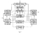
- the Queuing system block diagram according to Fig. 7 shows the input pipeline sending data to Put DMA and going on into the BlockRAM from where it go out to the SDRAM to be read back later. It then goes out through the Get DMA.
- the diagram also shows the passing of blocks around and the ownership of buffers. The diagram is replicated to highlight basic modes of operation:
- the diagram according to Fig. 8 shows how the Put Side gets a block to queue data into SDRAM and how the Get side gets another block to read the data out of SDRAM.
- the flow of blocks in the diagram according to Fig. 8 on the Put side is as follows:
- the Get side is similar, but it will in general use a different block to read out the data from SDRAM.
- segments are read from a short queue without having to be copied to SDRAM. This is the equivalent of burst aggregation in the Mx products.
- the block diagram according to Fig 10 also shows how the ownership of buffers is passed around the system.
- the diagram according to Fig. 10 shows the management of buffers in a queue.
Landscapes
- Engineering & Computer Science (AREA)
- Computer Networks & Wireless Communication (AREA)
- Signal Processing (AREA)
- Data Exchanges In Wide-Area Networks (AREA)
Claims (10)
- Verfahren zum Speichern von Frames oder anderen Datenpaketen in Warteschlangen in einer Massenspeichervorrichtung, das folgende Schritte aufweist:Aufteilen von mindestens einem Teil der Massenspeichervorrichtung in eine Anzahl von Puffern aus jeweils einem oder mehreren Chunks undBilden einer Warteschlange aus den Frames oder anderen Datenpaketen, die von einem Eingangskanal als eine Reihe von Segmenten ankommen, wobei ein Frame oder ein anderes Datenpaket in ein oder mehrere Segmente aufgeteilt sein kann,dadurch gekennzeichnet, dass,wenn ein Frame oder ein anderes Datenpaket in mehrere Segmente (1-6) aufgeteilt ist, jedes Segment (1-6) außer dem letzten jeweils einen Puffer komplett füllt,wobei an jedem Segment (1-6) außer dem letzten Segment eines Frames ein Verknüpfungsetikett angebracht ist, das dazu dient, Segmente (1-6) innerhalb der Massenspeichervorrichtung zu Frames zu verknüpfen, und es ermöglicht, dass Frames aus mehreren Strömen separat in dem Massenspeicher zusammengesetzt werden, bevor sie einer Warteschlange zugeordnet werden (Fig. 3).
- Verfahren nach Anspruch 1, bei dem ein oder mehrere Endsegmente eines Frames in einen oder mehrere Puffer gepackt werden.
- Verfahren nach Anspruch 1 oder 2, bei dem an jedem Endsegment eines Frames ein Verknüpfungsetikett angebracht ist, welches dazu dient, das Rücksetzen des Frames mit zu verknüpfen und die Puffer, in denen die Endpuffer in einem Massenspeicher gepackt sind, miteinander zu verknüpfen, um Warteschlangen zu bilden.
- Verfahren nach einem der vorhergehenden Ansprüche, bei dem an dem Eingangskanal die Frames oder andere Datenpakete aus einer Anzahl von Strömen auf der Segmentebene überlappend sein können.
- Verfahren nach einem der vorhergehenden Ansprüche, bei dem eine Warteschlange (Fig. 3) keinem bestimmten Eingangskanal dediziert ist, so dass jeder Strom des Eingangskanals in jede Warteschlange schreiben kann.
- Verfahren nach einem der vorhergehenden Ansprüche, bei dem in dem Fall, dass ein aus mehreren Segmenten bestehender Frame empfangen wird, alle Segmente (1-6) außer dem letzten in einer verknüpften Liste gespeichert werden.
- Verfahren nach Anspruch 6, bei dem eine verknüpfte Liste pro Strom erforderlich ist.
- Verfahren nach Anspruch 6 oder 7, bei dem die Verknüpfung durch den Mechanismus zur Bildung der Warteschlange unter Verwendung des Verknüpfungsfelds in dem Verknüpfungsetikett, das an jedem Segment (1-6) angebracht ist, erzielt wird.
- Verfahren nach einem der vorhergehenden Ansprüche, bei dem ein lokaler Speicher, insbesondere ein internes Block-RAM, und die Massenspeichervorrichtung von zwei Richtungen geteilt werden und die Massenspeichervorrichtung umgangen wird, wenn die Warteschlange klein ist.
- System zur Bildung einer Warteschlange zum Speichern von Frames oder anderen Datenpaketen in Warteschlangen in einer Massenspeichervorrichtung, mit:einer Massenspeichervorrichtung, bei der zumindest ein Teil derselben in eine Anzahl von Puffern aus jeweils einem oder mehreren Chunks aufgeteilt ist, undHardware-Mitteln, insbesondere einer FPGA- oder ASIC-Logik, um aus den Frames oder anderen Datenpaketen, die von einem Eingangskanal als eine Reihe von Segmenten ankommen, eine Warteschlange zu bilden, wobei ein Frame oder ein anderes Datenpaket in ein oder mehrere Segmente aufgeteilt sein kann,dadurch gekennzeichnet, dassdas System zur Bildung einer Warteschlange derart ausgebildet ist, dass, wenn ein Frame oder ein anderes Datenpaket in mehrere Segmente (1-6) aufgeteilt ist, jedes Segment (1-6) außer dem letzten jeweils einen Puffer komplett füllt,unddass das System zur Bildung einer Warteschlange derart ausgebildet ist, dass an jedem Segment (1-6) außer dem letzten Segment eines Frames ein Verknüpfungsetikett angebracht ist, das dazu dient, Segmente (1-6) innerhalb der Massenspeichervorrichtung zu Frames zu verknüpfen, und es ermöglicht, dass Frames aus mehreren Strömen separat in dem Massenspeicher zusammengesetzt werden, bevor sie einer Warteschlange zugeordnet werden (Fig. 3).
Priority Applications (2)
| Application Number | Priority Date | Filing Date | Title |
|---|---|---|---|
| DE602007012228T DE602007012228D1 (de) | 2007-07-10 | 2007-07-10 | NTU-Warteschlangensystem |
| EP07013474A EP2015521B1 (de) | 2007-07-10 | 2007-07-10 | NTU-Warteschlangensystem |
Applications Claiming Priority (1)
| Application Number | Priority Date | Filing Date | Title |
|---|---|---|---|
| EP07013474A EP2015521B1 (de) | 2007-07-10 | 2007-07-10 | NTU-Warteschlangensystem |
Publications (2)
| Publication Number | Publication Date |
|---|---|
| EP2015521A1 EP2015521A1 (de) | 2009-01-14 |
| EP2015521B1 true EP2015521B1 (de) | 2011-01-26 |
Family
ID=38573332
Family Applications (1)
| Application Number | Title | Priority Date | Filing Date |
|---|---|---|---|
| EP07013474A Active EP2015521B1 (de) | 2007-07-10 | 2007-07-10 | NTU-Warteschlangensystem |
Country Status (2)
| Country | Link |
|---|---|
| EP (1) | EP2015521B1 (de) |
| DE (1) | DE602007012228D1 (de) |
Family Cites Families (2)
| Publication number | Priority date | Publication date | Assignee | Title |
|---|---|---|---|---|
| WO1996017462A2 (en) * | 1994-11-21 | 1996-06-06 | Oracle Corporation | A reliable connectionless network protocol |
| US20060187963A1 (en) * | 2005-02-18 | 2006-08-24 | International Business Machines Corporation | Method for sharing single data buffer by several packets |
-
2007
- 2007-07-10 DE DE602007012228T patent/DE602007012228D1/de active Active
- 2007-07-10 EP EP07013474A patent/EP2015521B1/de active Active
Also Published As
| Publication number | Publication date |
|---|---|
| DE602007012228D1 (de) | 2011-03-10 |
| EP2015521A1 (de) | 2009-01-14 |
Similar Documents
| Publication | Publication Date | Title |
|---|---|---|
| US5758075A (en) | Multimedia communication apparatus and methods | |
| US6401149B1 (en) | Methods for context switching within a disk controller | |
| US6778548B1 (en) | Device to receive, buffer, and transmit packets of data in a packet switching network | |
| US7733878B2 (en) | System and method for packet transmission from fragmented buffer | |
| EP0797151B1 (de) | Rechnervorrichtung und Bussteuerungsschema | |
| US7155541B2 (en) | Tables with direct memory access descriptor lists for distributed direct memory access | |
| US5867731A (en) | System for data transfer across asynchronous interface | |
| JP4480845B2 (ja) | メモリー幅の非常に広いtdmスイッチシステム | |
| US7782849B2 (en) | Data switch and switch fabric | |
| US5793953A (en) | Method and apparatus for allowing packet data to be separated over multiple bus targets | |
| US10678718B2 (en) | Network device and method of operation | |
| JPWO2004057481A1 (ja) | Dma制御装置、dma制御方法、dma制御プログラム | |
| US7603488B1 (en) | Systems and methods for efficient memory management | |
| US6279052B1 (en) | Dynamic sizing of FIFOs and packets in high speed serial bus applications | |
| US8116306B2 (en) | Shared memory system | |
| US6622183B1 (en) | Data transmission buffer having frame counter feedback for re-transmitting aborted data frames | |
| KR100560277B1 (ko) | 메모리로의 액세스의 수를 감소시키는 방법 및 시스템 및 기록 매체 | |
| EP2015521B1 (de) | NTU-Warteschlangensystem | |
| EP1471430B1 (de) | Steuergerät für einen Datenstromspeicher | |
| CN1965550B (zh) | 处理完整数据突发的方法与装置 | |
| JP2005278175A (ja) | 誤り検査方法及び誤り検査システム | |
| JP6570075B2 (ja) | 通信用入出力装置 | |
| US7143185B1 (en) | Method and apparatus for accessing external memories | |
| JPH09138735A (ja) | 連続データサーバ装置、連続データ送出方法及びディスクアレイ装置 | |
| JP2002108800A (ja) | 集信装置に対する連結リストメモリアクセス制御 |
Legal Events
| Date | Code | Title | Description |
|---|---|---|---|
| PUAI | Public reference made under article 153(3) epc to a published international application that has entered the european phase |
Free format text: ORIGINAL CODE: 0009012 |
|
| AK | Designated contracting states |
Kind code of ref document: A1 Designated state(s): AT BE BG CH CY CZ DE DK EE ES FI FR GB GR HU IE IS IT LI LT LU LV MC MT NL PL PT RO SE SI SK TR |
|
| AX | Request for extension of the european patent |
Extension state: AL BA HR MK RS |
|
| 17P | Request for examination filed |
Effective date: 20090504 |
|
| 17Q | First examination report despatched |
Effective date: 20090709 |
|
| AKX | Designation fees paid |
Designated state(s): DE GB |
|
| RAP1 | Party data changed (applicant data changed or rights of an application transferred) |
Owner name: ADVA AG OPTICAL NETWORKING |
|
| GRAP | Despatch of communication of intention to grant a patent |
Free format text: ORIGINAL CODE: EPIDOSNIGR1 |
|
| GRAS | Grant fee paid |
Free format text: ORIGINAL CODE: EPIDOSNIGR3 |
|
| GRAA | (expected) grant |
Free format text: ORIGINAL CODE: 0009210 |
|
| AK | Designated contracting states |
Kind code of ref document: B1 Designated state(s): DE GB |
|
| REG | Reference to a national code |
Ref country code: GB Ref legal event code: FG4D |
|
| REF | Corresponds to: |
Ref document number: 602007012228 Country of ref document: DE Date of ref document: 20110310 Kind code of ref document: P |
|
| REG | Reference to a national code |
Ref country code: DE Ref legal event code: R096 Ref document number: 602007012228 Country of ref document: DE Effective date: 20110310 |
|
| PLBE | No opposition filed within time limit |
Free format text: ORIGINAL CODE: 0009261 |
|
| STAA | Information on the status of an ep patent application or granted ep patent |
Free format text: STATUS: NO OPPOSITION FILED WITHIN TIME LIMIT |
|
| 26N | No opposition filed |
Effective date: 20111027 |
|
| REG | Reference to a national code |
Ref country code: DE Ref legal event code: R097 Ref document number: 602007012228 Country of ref document: DE Effective date: 20111027 |
|
| REG | Reference to a national code |
Ref country code: DE Ref legal event code: R082 Ref document number: 602007012228 Country of ref document: DE Representative=s name: PATENTANWAELTE EDER & SCHIESCHKE, DE |
|
| REG | Reference to a national code |
Ref country code: DE Ref legal event code: R082 Ref document number: 602007012228 Country of ref document: DE Representative=s name: PATENTANWAELTE EDER & SCHIESCHKE, DE Effective date: 20131001 Ref country code: DE Ref legal event code: R081 Ref document number: 602007012228 Country of ref document: DE Owner name: ADVA OPTICAL NETWORKING SE, DE Free format text: FORMER OWNER: ADVA AG OPTICAL NETWORKING, 98617 MEININGEN, DE Effective date: 20131001 Ref country code: DE Ref legal event code: R082 Ref document number: 602007012228 Country of ref document: DE Representative=s name: EDER SCHIESCHKE & PARTNER MBB, PATENTANWAELTE, DE Effective date: 20131001 |
|
| P01 | Opt-out of the competence of the unified patent court (upc) registered |
Effective date: 20230630 |
|
| REG | Reference to a national code |
Ref country code: DE Ref legal event code: R081 Ref document number: 602007012228 Country of ref document: DE Owner name: ADTRAN NETWORKS SE, DE Free format text: FORMER OWNER: ADVA OPTICAL NETWORKING SE, 98617 MEININGEN, DE |
|
| PGFP | Annual fee paid to national office [announced via postgrant information from national office to epo] |
Ref country code: DE Payment date: 20250722 Year of fee payment: 19 |
|
| PGFP | Annual fee paid to national office [announced via postgrant information from national office to epo] |
Ref country code: GB Payment date: 20250724 Year of fee payment: 19 |