EP2015612A2 - Verfahren zur LED-Ansteuerung - Google Patents
Verfahren zur LED-Ansteuerung Download PDFInfo
- Publication number
- EP2015612A2 EP2015612A2 EP08160322A EP08160322A EP2015612A2 EP 2015612 A2 EP2015612 A2 EP 2015612A2 EP 08160322 A EP08160322 A EP 08160322A EP 08160322 A EP08160322 A EP 08160322A EP 2015612 A2 EP2015612 A2 EP 2015612A2
- Authority
- EP
- European Patent Office
- Prior art keywords
- led
- pulse signal
- leds
- driving
- current
- Prior art date
- Legal status (The legal status is an assumption and is not a legal conclusion. Google has not performed a legal analysis and makes no representation as to the accuracy of the status listed.)
- Withdrawn
Links
Images


Classifications
-
- H—ELECTRICITY
- H05—ELECTRIC TECHNIQUES NOT OTHERWISE PROVIDED FOR
- H05B—ELECTRIC HEATING; ELECTRIC LIGHT SOURCES NOT OTHERWISE PROVIDED FOR; CIRCUIT ARRANGEMENTS FOR ELECTRIC LIGHT SOURCES, IN GENERAL
- H05B45/00—Circuit arrangements for operating light-emitting diodes [LED]
- H05B45/40—Details of LED load circuits
- H05B45/44—Details of LED load circuits with an active control inside an LED matrix
- H05B45/46—Details of LED load circuits with an active control inside an LED matrix having LEDs disposed in parallel lines
Definitions
- the present invention relates to a method for driving a LED, and more particularly, to a method for driving a LED which can effectively enhance the light intensity of a LED.
- the nominal power is the electric power with which the LEDs shall be driven.
- the nominal power is limited. If a LED is driven with an electric power larger than the nominal power the increase in brightness is lower than below the nominal power. This effect is well known and to minimize this effect it is known to actively cool the LEDs. However, an active cooling is very laborious and in most applications of LEDs it is not possible to provide a suitable cooling mechanism.
- the breakdown state is achieved the brightness can not be further increased even if a higher electric power is applied.
- the breakdown state is usually achieved with a current of more than about 40% to 50% of the nominal constant current. For example, if the nominal constant current is about 350 mA then the breakdowns state is achieved by about 500 mA.
- the standard LEDs have a nominal power of about 1.2 W. There are also known high power LEDs with a nominal power of about 3 W or 5 W. A nominal constant current corresponds to a nominal power as the LEDs are always driven with a voltage of 3.5 V. So the nominal power is the nominal constant current multiplied with 3.5 V.
- US 6,028,694 discloses an illumination device using a pulse modulation technique for providing an increased light output for a given heat load.
- This illumination device is designed for being used in surgery applications.
- the power is supplied in pulses to periodically activate a short wavelength emitting LED.
- This light pulses are stimulating a phosphor-based color conversion system to produce white light.
- the light pulse from the LED briefly excites the phosphor system, producing a bright illumination during the interval while power is dissipated in the LED, the LED warms. After the pulse ends and before the next pulse begins, the LED cools because no more power is dissipated in the LED.
- the intensity of the illumination produced by the phosphor gradually decays between the light pulses.
- the average illumination produced over the entire period is higher than a conventional LED illumination device using constant power dissipation for a given heat load.
- this device is designed to be used in a human body it is only driven with a low electric power, because else the human body would be injured due to the created heat.
- the present invention provides a method for driving a LED which can enhance the light intensity of a LED.
- One aspect of the present invention is a method for driving a LED by a pulse signal, wherein the pulse signal comprises pulses of a duration of T/n, wherein T is the duration of a single pulse and the corresponding pause in between two consecutive pulses and n is at least 2, and the current value of the pulses is at least double as much as the nominal constant current of said LED.
- a further aspect of the present invention is to drive a LED by a pulse signal, wherein an electric power of at least 90% of the nominal power of said LED is applied to the LED. Applying the same amount of electric power by means of constant current would result in a significant lower brightness. This high yield of brightness is achieved without active cooling. Thus the maximum brightness or luminance of an LED can be significantly increased. With the present invention a high electric power can be applied to a LED without an increased effectiveness of the conversion of electric power to electric light. Due to the pulse signal the impact of the breakdown state is shifted to higher electric power.
- the LED is driven with an electric power of at least 80%, or at least 100% or even more preferably 110% of the nominal power for applying constant current.
- the pulse signal can comprise pulses of a duration of T/n, wherein T is the duration of the pulse and the pause in between two consecutive pulses and the current of each pulse is at least n times the nominal constant current of said LED.
- n is at least 3, or at least 4 or larger.
- the light efficiency can be further increased if the LED is cooled.
- the cooling can be carried out by means of a passive cooling block (e.g. block of aluminum with cooling ribs) or by means of an active cooling element (e.g. peltier element, fan).
- a passive cooling block e.g. block of aluminum with cooling ribs
- an active cooling element e.g. peltier element, fan
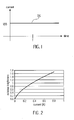
- Fig. 1 shows a waveform of a conventional driving current signal DS for a light-emitting diode (LED) which is operated at a prescribed constant driving voltage of V and a prescribed constant driving current of I such that the prescribed power consumption P of the LED in a prescribed unit of time T is V x I.
- LED light-emitting diode
- I the prescribed power consumption
- a LED which is operated at a prescribed constant driving current of 350 mA and a prescribed constant driving voltage of 1 V to emit light with an intensity of 30 Ix
- the light intensity increases accordingly, based on the relationship between the current value of the driving current signal and the light intensity shown in Fig. 2 .
- the LED having the characteristics shown in Fig. 2 is available in the market.
- a driving pulse signal PS used in the method of the present invention is shown. It can be seen from Fig. 2 , the light intensity will increase as the current value of the driving current signal is increased. Therefore, in the method of the present invention, a driving pulse signal PS, the cycle of which is equal to the prescribed unit of time T, is provided to the LED.
- the peak value of each of the pulse signals PS is n times the current value of the signal DS, and the high voltage level duration of the pulse signal PS is (T/n'), wherein n and n' are both positive integer excluding 0 and 1, and (n/n') ⁇ 1.
- the power consumption of the LED is increased by n times because the current value of the driving pulse signal PS at its high voltage level is n times the current value of the signal DS, thereby increasing the light intensity n times.
- n is equal to 4
- the current value of the current is 350 mA
- the light intensity in the high voltage level duration T/n' increases 4 times.
- the total power consumption is still 1 W. Therefore, the total power consumption is unchanged while the light intensity increases n times.
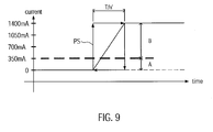
- the light intensity will increase as the current value of the driving current signal is increased, however, the number of times is not unlimited. As shown in Fig. 9 , when the magnitude of the current is increased to some extent, the LED enters to the breakdown state. At this time, the light intensity will not increase anymore, even though the magnitude of the current is continuously increasing. It is noted that the current value for the breakdown state is at a higher level for a pulse signal than for a constant current.
- the selection of n is in relation to the high voltage level duration (T/n'), and the selection of the high voltage level duration (T/n') is based on the effective slope of the current of the LED. In Fig.
- the magnitude of the current in Fig. 9 is by way of example, the present invention is not limited thereto.
- the arrow indicates the loop formed by the rising edge, the high voltage level duration, and the falling edge of the pulse, that is, the conditions based thereupon the peak value of the pulse and the high voltage level duration is selected.
- Fig. 19 shows schematically the effect of driving a LED with constant current (graph II) and with a pulse signal (graph I; T/3).
- graph II constant current
- graph I pulse signal
- FIG. 19 shows schematically the effect of driving a LED with constant current (graph II) and with a pulse signal (graph I; T/3).
- N nominal constant current of 350 mA
- NC nominal constant current of 350 mA
- BS breakdown state current
- graph I When the LED is driven with a pulse signal (graph I) it is possible to apply a much higher current without an effect of the breakdown state. Thus it is possible to reach a much higher brightness.
- Fig. 19 shows schematically the effect of driving a LED with constant current (graph II) and with a pulse signal (graph I; T/3).
- NC nominal constant current of 350 mA
- BS breakdown state current
- n 3, which means that the duration of the pulses is T/3 and the duration of the pauses between two consecutive pulses is 2T/3.
- a very high brightness is achieved using a pulse signal and applying an electric power of at least 80% or at least or at least 90% of the nominal electric power.
- the electric power can be at least 100%, or 110%, or 120% or 130% of the nominal power. If an electric power of more than 100% of the nominal power it is advisable to provide a passive or an active cooling means.
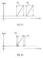
- the LEDs are correspondingly driven by two identical driving pulse signals PS1, PS2 when the method of the present invention is used to drive two or more LEDs in series connection. Therefore, in comparison with Fig. 1 , the light intensity will increase n x m times in the high voltage level duration (T/n'), wherein m is the number of LED and is 2 in the embodiment shown in Fig. 10 .
- the LEDs are correspondingly driven by two identical driving pulse signals PS1, PS2 when the method of the present invention is used to drive two or more LEDs in parallel connection. If the phases of the driving pulse signals PS1,PS2 are the same, that is, the driving pulse signals PS1,PS2 are synchronously provided to the corresponding LEDs, in comparision with Fig. 1 , the light intensity will also increase n x m times in the high voltage level duration (T/n').
- the LEDs are correspondingly driven by two driving pulse signals PS1,PS2' having different phases.
- the phases of the driving pulse signals PS1,PS2 are different, but the peak value and the cycle time are the same.
- the phase difference diff between the driving pulse signals PS1 and PS2' can be selected depending on what is needed.
- the power consumption of PS1 during the high voltage level duration (T/n') is 1400mA x 3.5V ⁇ 4W
- the power consumption of PS2' during the high voltage level duration (T/n') is 1400mA x 3.5V ⁇ 4W. Therefore, the power consumption of PS1 in a unit of time T is about 0.5W, and the power consumption of PS2' is about 0.5W. Therefore, two parallel-connected 1400mA currents can increase 8W slope and the light intensity, but the power consumption in a unit of time T is still about 1 W.
- the cap surface of the LED will be coated with a photoluminescent material which can absorb the ambient light and emit the absorbed light, such that the photoluminescent material will emit the light absorbed during the high voltage level duration (T/4) during the low voltage level duration (T-(T/4)).
- the shadow portion is the low voltage level duration (T-(T/4)) during which the photoluminescent material release the stored photo energy.
- the intensity of light emitted from the photoluminescent material is about 80% of that from the LED. As shown in Fig.
- the low energy level L is a level corresponding to the low voltage level of the driving pulse signal
- the high energy level H is a level corresponding to the high voltage level of the driving pulse signal
- the excitation energy level E is a level above which the LED emits light.
- a cycle from the low energy level to the high energy level, from the high energy level to the excitation energy level, and from the excitation energy level total takes 100 nsec. It should be noted that, when the driving pulse signal transits from the low voltage level to the high voltage level, the LED emits light, and the photoluminescent material on the LED absorbs and stores the photo energy from the emitted light.
- the LED When the driving pulse signal transits from the high voltage level to the low voltage level, the LED will cease to emit light after down from the excitation energy level E to the low energy level L. In the meantime, the photoluminescent material will release the stored photo energy until the driving pulse signal transits from the low voltage level to the high voltage level. Therefore, in order to prevent flickering phenomenon from occurring at the time of (T-(T/4)), a condition that the duration during which the photoluminescent material coated on a LED releases stored photo energy is greater than the pulse cycle, and the pulse cycle is greater than 100 nsec., must be satisfy.
- the photoluminescent material may be doped with fluorescent powder or phosphorus powder.
- the LED shown in Fig. 7 is by way of example, the photoluminescent material may be coated on the lighting surface of any LED package.
- Figs. 13 to 15 are three LED driving circuitry examples that are adapted to be used in the present invention.
- Fig. 16 is a schematic diagram showing various LED array examples adapted to be driven by the method according to the present invention.
- the frequency of the driving pulse signal may be set to 32Hz or above.
- a conventional RC circuitry can also be used to prevent flickering phenomenon from occurring, instead of the photoluminescent material.
Landscapes
- Led Devices (AREA)
Priority Applications (1)
| Application Number | Priority Date | Filing Date | Title |
|---|---|---|---|
| EP08160322A EP2015612A3 (de) | 2007-07-12 | 2008-07-14 | Verfahren zur LED-Ansteuerung |
Applications Claiming Priority (2)
| Application Number | Priority Date | Filing Date | Title |
|---|---|---|---|
| EP07112349A EP2015611A1 (de) | 2007-07-12 | 2007-07-12 | Verfahren zur LED-Ansteuerung |
| EP08160322A EP2015612A3 (de) | 2007-07-12 | 2008-07-14 | Verfahren zur LED-Ansteuerung |
Publications (2)
| Publication Number | Publication Date |
|---|---|
| EP2015612A2 true EP2015612A2 (de) | 2009-01-14 |
| EP2015612A3 EP2015612A3 (de) | 2012-02-08 |
Family
ID=38596711
Family Applications (2)
| Application Number | Title | Priority Date | Filing Date |
|---|---|---|---|
| EP07112349A Withdrawn EP2015611A1 (de) | 2007-07-12 | 2007-07-12 | Verfahren zur LED-Ansteuerung |
| EP08160322A Withdrawn EP2015612A3 (de) | 2007-07-12 | 2008-07-14 | Verfahren zur LED-Ansteuerung |
Family Applications Before (1)
| Application Number | Title | Priority Date | Filing Date |
|---|---|---|---|
| EP07112349A Withdrawn EP2015611A1 (de) | 2007-07-12 | 2007-07-12 | Verfahren zur LED-Ansteuerung |
Country Status (1)
| Country | Link |
|---|---|
| EP (2) | EP2015611A1 (de) |
Families Citing this family (3)
| Publication number | Priority date | Publication date | Assignee | Title |
|---|---|---|---|---|
| CN102468414B (zh) * | 2010-11-09 | 2014-08-13 | 四川新力光源股份有限公司 | 脉冲led白光发光装置 |
| CN102466146B (zh) * | 2010-11-09 | 2014-06-25 | 四川新力光源股份有限公司 | 一种脉冲led发光装置 |
| EP2695486A2 (de) | 2011-04-04 | 2014-02-12 | Sgm A/S | Verfahren zum betreiben von leds |
Citations (1)
| Publication number | Priority date | Publication date | Assignee | Title |
|---|---|---|---|---|
| US6028694A (en) | 1997-05-22 | 2000-02-22 | Schmidt; Gregory W. | Illumination device using pulse width modulation of a LED |
Family Cites Families (2)
| Publication number | Priority date | Publication date | Assignee | Title |
|---|---|---|---|---|
| GB2408315B (en) * | 2003-09-18 | 2007-05-16 | Radiant Res Ltd | Illumination control system for light emitters |
| CN101243557B (zh) * | 2005-08-15 | 2010-11-10 | 皇家飞利浦电子股份有限公司 | 用于产生颜色和/或亮度可改变的光的光源和方法 |
-
2007
- 2007-07-12 EP EP07112349A patent/EP2015611A1/de not_active Withdrawn
-
2008
- 2008-07-14 EP EP08160322A patent/EP2015612A3/de not_active Withdrawn
Patent Citations (1)
| Publication number | Priority date | Publication date | Assignee | Title |
|---|---|---|---|---|
| US6028694A (en) | 1997-05-22 | 2000-02-22 | Schmidt; Gregory W. | Illumination device using pulse width modulation of a LED |
Also Published As
| Publication number | Publication date |
|---|---|
| EP2015611A1 (de) | 2009-01-14 |
| EP2015612A3 (de) | 2012-02-08 |
Similar Documents
| Publication | Publication Date | Title |
|---|---|---|
| US8314565B2 (en) | Solid state LED bridge rectifier light engine | |
| US8497621B2 (en) | Illuminating device with light buffer | |
| US6028694A (en) | Illumination device using pulse width modulation of a LED | |
| EP2522200B1 (de) | Led lichtkreis | |
| US20120256550A1 (en) | Led driving circuit | |
| RU2596804C2 (ru) | Линейный формировательсигнала питания для уменьшенного воспринимаемого светового мерцания | |
| CN102164435A (zh) | 用于触发发光机构的电路和方法 | |
| EP2015612A2 (de) | Verfahren zur LED-Ansteuerung | |
| JP2009206383A (ja) | Ledモジュール及びそれを備えるled点灯装置 | |
| US8253345B2 (en) | Method for driving LED | |
| US8193716B2 (en) | High-power LED driving circuit | |
| JP2008262966A (ja) | 発光ダイオード駆動装置 | |
| US20090015169A1 (en) | Method for Driving an LED | |
| KR200462911Y1 (ko) | 집어등 장치 | |
| JP2007012808A (ja) | 交流電源用発光装置 | |
| KR102323418B1 (ko) | 방열특성이 개선된 발광다이오드 조명장치 | |
| US20110260642A1 (en) | Inductive current-sharing control circuit for led lamp string | |
| KR20110000534U (ko) | 엘이디 조명 장치 | |
| KR20160043760A (ko) | 발광소자 구동회로 | |
| JP4277610B2 (ja) | 発光装置 | |
| KR101945263B1 (ko) | 발광장치 | |
| US7843423B2 (en) | Driving device for driving a light emitting unit | |
| JP6288814B2 (ja) | 発光素子駆動装置 | |
| KR100983042B1 (ko) | 조명 장치 | |
| JP2014130797A (ja) | 照明灯具 |
Legal Events
| Date | Code | Title | Description |
|---|---|---|---|
| PUAI | Public reference made under article 153(3) epc to a published international application that has entered the european phase |
Free format text: ORIGINAL CODE: 0009012 |
|
| AK | Designated contracting states |
Kind code of ref document: A2 Designated state(s): AT BE BG CH CY CZ DE DK EE ES FI FR GB GR HR HU IE IS IT LI LT LU LV MC MT NL NO PL PT RO SE SI SK TR |
|
| AX | Request for extension of the european patent |
Extension state: AL BA MK RS |
|
| PUAL | Search report despatched |
Free format text: ORIGINAL CODE: 0009013 |
|
| AK | Designated contracting states |
Kind code of ref document: A3 Designated state(s): AT BE BG CH CY CZ DE DK EE ES FI FR GB GR HR HU IE IS IT LI LT LU LV MC MT NL NO PL PT RO SE SI SK TR |
|
| AX | Request for extension of the european patent |
Extension state: AL BA MK RS |
|
| RIC1 | Information provided on ipc code assigned before grant |
Ipc: H05B 33/08 20060101AFI20111230BHEP |
|
| AKY | No designation fees paid | ||
| REG | Reference to a national code |
Ref country code: DE Ref legal event code: R108 |
|
| REG | Reference to a national code |
Ref country code: DE Ref legal event code: R108 Effective date: 20121017 |
|
| STAA | Information on the status of an ep patent application or granted ep patent |
Free format text: STATUS: THE APPLICATION IS DEEMED TO BE WITHDRAWN |
|
| 18D | Application deemed to be withdrawn |
Effective date: 20120809 |