EP2015663B1 - Lebensmittelmühle mit entfernbarer messeranordnung - Google Patents
Lebensmittelmühle mit entfernbarer messeranordnung Download PDFInfo
- Publication number
- EP2015663B1 EP2015663B1 EP07751684.7A EP07751684A EP2015663B1 EP 2015663 B1 EP2015663 B1 EP 2015663B1 EP 07751684 A EP07751684 A EP 07751684A EP 2015663 B1 EP2015663 B1 EP 2015663B1
- Authority
- EP
- European Patent Office
- Prior art keywords
- flange
- latch
- support arm
- base
- lever
- Prior art date
- Legal status (The legal status is an assumption and is not a legal conclusion. Google has not performed a legal analysis and makes no representation as to the accuracy of the status listed.)
- Not-in-force
Links
Images


Classifications
-
- B—PERFORMING OPERATIONS; TRANSPORTING
- B26—HAND CUTTING TOOLS; CUTTING; SEVERING
- B26D—CUTTING; DETAILS COMMON TO MACHINES FOR PERFORATING, PUNCHING, CUTTING-OUT, STAMPING-OUT OR SEVERING
- B26D7/00—Details of apparatus for cutting, cutting-out, stamping-out, punching, perforating, or severing by means other than cutting
- B26D7/26—Means for mounting or adjusting the cutting member; Means for adjusting the stroke of the cutting member
-
- A—HUMAN NECESSITIES
- A47—FURNITURE; DOMESTIC ARTICLES OR APPLIANCES; COFFEE MILLS; SPICE MILLS; SUCTION CLEANERS IN GENERAL
- A47J—KITCHEN EQUIPMENT; COFFEE MILLS; SPICE MILLS; APPARATUS FOR MAKING BEVERAGES
- A47J19/00—Household machines for straining foodstuffs; Household implements for mashing or straining foodstuffs
- A47J19/005—Hand devices for straining foodstuffs
-
- B—PERFORMING OPERATIONS; TRANSPORTING
- B26—HAND CUTTING TOOLS; CUTTING; SEVERING
- B26D—CUTTING; DETAILS COMMON TO MACHINES FOR PERFORATING, PUNCHING, CUTTING-OUT, STAMPING-OUT OR SEVERING
- B26D7/00—Details of apparatus for cutting, cutting-out, stamping-out, punching, perforating, or severing by means other than cutting
-
- B—PERFORMING OPERATIONS; TRANSPORTING
- B26—HAND CUTTING TOOLS; CUTTING; SEVERING
- B26D—CUTTING; DETAILS COMMON TO MACHINES FOR PERFORATING, PUNCHING, CUTTING-OUT, STAMPING-OUT OR SEVERING
- B26D3/00—Cutting work characterised by the nature of the cut made; Apparatus therefor
- B26D3/24—Cutting work characterised by the nature of the cut made; Apparatus therefor to obtain segments other than slices, e.g. cutting pies
- B26D3/26—Cutting work characterised by the nature of the cut made; Apparatus therefor to obtain segments other than slices, e.g. cutting pies specially adapted for cutting fruit or vegetables, e.g. for onions
Definitions
- the present invention is directed to a food mill, and more specifically, to a food mill including a removable blade assembly.
- a food mill which includes a container having one of a plurality of interchangeable blades which process one or more food items.
- food mills include a container having a handle and a blade which is positioned in the bottom of the container.
- the blade may have different sized openings.
- the food mill may include a plate which is biased toward the blade at the bottom of the food mill which may be connected to a handle that is rotatably connected to the food mill. A user rotates the handle which causes the plate to rotate and press against a food item placed in the food mill.
- the food item is pressed into and cut or sliced by the blade and the cut portion of the food item falls into a separate container, such as a bowl.
- a blade assembly and more specifically the handle, is held in position by a support bar which is connected to opposing sides of the food mill.
- Most conventional food mills have removable support arms which enable a user to remove the entire blade assembly for cleaning. It also allows the user to remove the blade assembly to place one or more food items in the container of the food mill.
- it is difficult to reinsert the blade assembly after one or more food items are placed in the food mill because the tension of the spring positioned between the plate and the support is high. Therefore a user has to struggle to reinsert the blade assembly and more specifically, position and connect the opposing ends of the support arms to the food mill.
- the apparatus comprises a flat-bottomed perforated receptacle and a pressure vane secured on the lower end of a vertical shaft or axle rotatably mounted in said receptacle.
- Said vane is formed of a sector-shaped metal plate having an arc length of about 270° and flared in such manner as to present a steeply inclined portion of its surface for the preliminary straining of the food.
- said vane comprises a succeeding portion less steeply sloped for tightly squeezing and partially forcing the food through the perforations in the flat bottom of the receptacle.
- said vane comprises a short sharply down-turned end portion for finally pressing the food through the holes and mincing it.
- One embodiment of the present invention provides a food mill including a container including a first flange and an opposing second flange and a blade assembly that is removably connected to the container.
- the blade assembly includes a support arm having a first end defining a slot engageable with the first flange, and a second end including a latch.
- the latch is movable between a first condition, where the latch is dis-engaged from the second flange, and a second condition, where the latch is engaged with the second flange.
- the latch includes a base that is movably connected to the support arm, a lever movably connected to the base and a bias member connected to the base.
- the bias member is adapted to bias the base towards the second flange, where when the latch is moved to the first condition, the base pivots to dis-engage from the second flange, and wherein when the latch is moved to the second condition, the base pivots to engage the second flange.
- the lever moves away from the second flange when the latch is moved to the first condition, and the lever moves toward the second flange when the latch is moved to the second condition.
- the latch includes a base movably connected to the support arm and a lever slidably connected to the base and the support arm.
- the lever is slidable in a slot defined by the second end of the support arm, where when the lever is slid away from the second end, the base pivots away from the second flange, and when the lever is slid toward the second end, the base pivots toward the second flange.
- the food mill includes a handle rotatably connected to the support arm.
- the handle includes a first end and a second end.
- the first end includes a knob and the second end includes a pressure plate and a bias member, where the bias member biases the pressure plate away from the support arm.
- the bias member is a spring positioned between the pressure plate and the support arm.
- the food mill includes an interchangeable cutting member seated in the container.
- the food mill includes a handle connected to the container.
- the food mill includes a pair of legs pivotably connected to the container, where each of the legs pivots between a first position adjacent to the container and a second position away from the container.
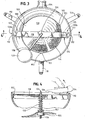
- FIG. 1 Another embodiment provides a blade assembly attachable to a food mill, where the food mill includes a first flange and an opposing second flange.
- the blade assembly includes a support arm having a first end and an opposing second end. The first end defines a first slot and the second end defines a second slot. The first slot is removably connected to the first flange, and the second slot is removably connected to the second flange.
- the blade assembly includes a latch that is movably connected to at least the first end of the support arm. The latch is movable between a first condition, where the latch is dis-engaged from the first flange, and a second condition, where the latch is engaged with the first flange to secure the blade assembly to the food mill.
- the latch includes a base, a lever movably connected to the base and a bias member connected to the base.
- the bias member is adapted to bias the base toward and away from the first flange, where when the latch is moved to the first condition, the base pivots away from the first flange, and when the latch is moved to the second condition, the base pivots toward the first flange.
- the lever is moved away from the first flange when the latch is moved to the first condition, and the lever is moved toward the second flange when the latch is moved to the second condition.
- the latch includes a lever movably connected to a base, where the lever is slidable in a slot defined by the second end of the support arm.
- the lever When the lever is slid away from the second end, the base pivots away from the first flange, and when the lever is slid toward the second end, the base pivots toward the first flange.
- the blade assembly includes a handle rotatably connected to the support arm.
- the handle includes a first end and a second end.
- the first end includes a knob and the second end includes a pressure plate and a bias member, where the bias member biases the pressure plate away from the support arm.
- the bias member is a spring positioned between the pressure plate and the support arm.
- Another advantage of the present invention is to provide a blade assembly for a food mill which can be removed using one hand.
- the present invention is directed generally to a food mill and, more specifically, to a food mill including a removable blade assembly having a quick release latch which enables the blade assembly to be easily removable and re-insertable into the food mill.
- the food mill includes a container 102, a cutting member 114 positioned in the container, and a blade assembly 116 which is removably connected to the container.
- the container 102 is a generally circular container or bowl that resembles a pot or similar container.
- the container may be circular, square, rectangular or any suitable size and shape.
- a handle 104 is connected to the container 102 and enables a user to securely hold the container. As shown in Fig. 1 , the handle extends substantially horizontally from the container. In an embodiment, the handle 104 defines at least one opening 106.
- the opening 106 is adapted to enable a user to hang and store the food mill 100 on a hook or other similar member for storage.
- the handle 104 has a generally oblong, elongated shape but may be any suitable size and shape. In an embodiment, the handle may be a separate component which is connected to the container 102. In another embodiment, the handle 104 may be integrally formed with the container 102.
- At least one, and preferably a plurality of legs 110 are pivotably connected to the container 102.
- Each leg 110 pivots between a first position adjacent to the container and a second position extending a designated distance away from the container.
- each of the legs 110 When fully extended, each of the legs 110 is substantially horizontal and engages a wall or lip of a separate underlying container such as a bowl (not shown).
- the legs 110 therefore provide support and stability to the food mill as it rests on the separate container or bowl during use.
- the legs 110 may be of any suitable size and shape. It should also be appreciated that one, two or more legs 110 may be connected to the container 102.
- the bottom of the container 102 defines a generally circular opening (not shown) which is formed to receive a cutting member or blade 114.
- the bottom of the container 102 defines a plurality of recesses 103 which have a size and shape that corresponds to protrusions 105 defined by the blade 114. This enables the blade to be properly positioned and seated in the bottom of the container.
- a plurality of blades 114 may be designed to be seated in the bottom of the container 102 and may be interchangeable, depending on the food preparation needed. The blades, therefore, may include relatively small or relatively large holes or a combination of large and small holes.
- the container 102 includes a pair of opposing flanges 112.
- the opposing flanges 112 are separate parts which are connected to the inside surface of the container 102.
- the opposing flanges 112 are integrally formed with the inside surface of the container.
- Each of the flanges includes a substantially planar portion which is transverse to the inside surface of the container and a downwardly extending lip portion. It should be appreciated that the first and second flanges 112 may be of any suitable size or shape.
- the blade assembly or crank assembly 116 is positioned in the container 102 and secured in place by engaging the blade assembly with the first and second flanges 112.
- the blade assembly 116 includes a cross bar or support arm 118 which is a substantially horizontal member having a first end 120a and an opposing second end 120b.
- the support arm 118 defines end slots 122 at each of the first and second ends 120a and 120b.
- Each of the end slots 122 is a generally oval, elongated opening. It should be appreciated that the end slots may be of any suitable size or shape.
- Each of the end slots 122 include a size and shape which corresponds to the size and shape of the flanges or tabs 112. As shown in Figs. 3-4 , the flanges 112 curve and form a lip portion 150 which extend respectively downwardly through the end slots 122. Additionally, the middle or center portion of the support arm 118 defines a center opening 124.
- a generally L-shaped arm 126 is rotatably connected to the opening 124 where one end of the arm 126 extends below the support arm 118 and the other end of the arm 126 is transverse to and extends generally outwardly away from the support arm 118.
- the end of arm 126 which extends below the support arm 118 towards the bottom of the container 102 is inserted through an opening defined by a rotatable member or rotatable plate 130 and into an opening defined in the center of the blade 114.
- the opening in the blade helps secure the arm 126 in place and minimize lateral movement of the blade assembly.
- the plate 130 is secured to the arm 126 using stop washers 153 and 155. It should be appreciated that any suitable connector or fasteners may be used to secure the plate 130 in place.
- the opposing end of the arm 126 includes a knob 128 which enables a user to manipulate and rotate the arm 126 with respect to the support arm 118.
- the knob 128 may be rotatably connected to the arm 126 to facilitate the rotation of the arm 126 with respect to the support arm 118.
- the knob 128 defines a plurality of knurls or protrusions which enables a user to securely grab and hold the knob 128.
- the plate 130 has a size and shape (i.e., surface area) which is less than the size and shape of the blade 114.
- a bias member or spring 132 is positioned about the arm 126 between the plate 130 and the bottom of the support arm 118.
- the spring 132 is a coil spring which biases the plate 130 downwardly toward the bottom of the container.
- the downward pressure of the plate 130 on one or more food items causes the food items to be pressed into the blade 114 as the plate 130 rotates. This causes the food item or items to be cut or sliced by the blade and processed by the food mill.
- a lever assembly or latch 134 is movably connected to at least one end of the support arm 118 in a slot 135.
- the latch 134 facilitates the easy removal and re-insertion of the support arm and thereby the blade assembly 116 with the container 102.
- a latch 134 is movably connected to a lever slot 135 defined by the support arm 118.
- the latch 134 includes a switch 136 having a generally T-shaped bottom portion which slidably engages a slot or channel 140 defined by the top of base 138.
- the base 138 defines a pair of openings 139a and 139b. After the latch is positioned in the support arm 118, openings 139a and 139b are aligned with corresponding openings 141 on the outside surfaces of the support arm 118.
- a pivot spring 144 having a generally V-shaped configuration is positioned so that pivot pin 142 is inserted through one side of the support arm 118 through the pivot spring 144 and the opening 139a defined by the base 138.
- the pivot pin 142 extends a predetermined distance from the opposing side of the support arm.
- a suitable connector may be connected to the opposing end of the pivot pin 142 to hold or secure it in place.
- the pivot pin 142 is a rivet or similar connector which can be manipulated by the use of a tool to deform the pin and prevent the pin from being removed from the support arm.
- a stop pin 146 is inserted through the other opening defined by the side of the support arm and moves through a pivot slot 148 defined by the base 138.
- the opposing end of the stop pin 146 extends through a corresponding hole or opening defined on the opposite side of the support arm 118.
- a suitable connector is used to secure the stop pin 146 to the support arm so the stop pin does not fall out.
- the stop pin 146 could be a rivet or similar connector.
- the stop pin is connected so that it is able to move or slide within the slotted opening 139b.
- the stop pin 148 is positioned to support and provide resistance for a portion of the pivot spring 144. This causes the spring 144 to have a predetermined tension to cause the base 138 to pivot, as described in detail below.
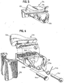
- a user wishes to remove the blade assembly 116 from the container 102, the user places one hand, and more particularly, a finger, such as their thumb, on the switch 136. The user then presses or pushes the switch 136 inwardly toward the center of the support arm 118. The inward movement of the switch 136 causes the base 138 to pivot from a first position, where engagement surface 148 is in contact with the lip portion 150 of the flange 112, to a second position, where the engagement surface 148 is not in contact with the lip portion 150 of flange 112.
- the base 138 pivots about pivot pin 142 which causes the stop pin 146 to move from the lower position of slotted opening 139b to the top of the opening 139b.
- This movement of stop pin 146 presses one side of the pivot spring 144 inwardly to increase the tension on the spring.
- the spring 144 biases the stop pin 146 toward the lower position in the pivot slot 148 shown in Figs. 7A and 8A .
- the user may now tilt or pivot the support arm 118 downward to release and/or remove the end of the support arm from the container 102.
- the user pivots the support arm 118 to engage the end slot 122 (on the side of the support arm opposite to the side including the latch assembly 134) with the lip portion 150 of one of the flanges 112.
- the user pivots the opposing end of the support arm 118 downward toward the opposing flange 122 until the engagement surface 148 contacts the lip portion 150 of this flange as shown in Fig. 7A .
- the user continues to move or pivot the support arm 118 downwardly causing the engagement surface 148 to move along the outside surface of the lip portion 150, as shown in Fig. 7B , until the top of the engagement surface 148 is below the bottom of the lip portion.
- the base 138 then pivots back to its original position as shown in Fig. 8A where the engagement surface 148 is in contact with the lip portion 150 of the flange 112 to secure the support arm 118 in place.
- the user can manipulate the lever 136 to connect the support arm 118 to the flange.
- the user grasps lever or switch 136 and moves or pushes it inwardly toward the center of the support arm 118 as shown in Fig. 8B .
- This causes the base 138 to pivot about pivot pin 142 and stop pin 146 to move to the upper or top position of opening 139b thereby compressing pivot spring 144.
- the user releases the switch 136 to enable the base 138 to move back to its original position.
- the pivot spring 144 pushes against the stop pin 146 to cause the stop pin to move to the lower or bottom position of the slotted opening 139b as shown in Fig. 8A .
- This causes the base 138 to pivot with respect to the support arm 118 so that the engagement surface 148 of the base engages and/or contacts the lip portion 150 of flange 112 to securely hold the end of the support arm 118 in place in the food mill as described above.
- the quick and easy one-handed or single-handed operation of the latch 134 to remove or release and re-insert the blade assembly 116 from the container reduces, if not eliminates, the difficulty users incur when removing and/or re-inserting conventional blade assemblies in a food mill.
- the latch of the present invention makes removal and/or re-insertion of the blade assembly in a food mill much more efficient and easier for users.
- each end of the support arm may include a latch or latch assembly to further enhance the removal and re-insertion of the blade assembly with the container of the food mill.
Landscapes
- Engineering & Computer Science (AREA)
- Life Sciences & Earth Sciences (AREA)
- Forests & Forestry (AREA)
- Mechanical Engineering (AREA)
- Food Science & Technology (AREA)
- Food-Manufacturing Devices (AREA)
- Crushing And Pulverization Processes (AREA)
Claims (15)
- Eine Lebensmittelmühle (100), umfassend:einen Behälter (102) mit einem ersten Flansch (112) und einem gegenüberliegenden zweiten Flansch (112), undeine Blattanordnung (116), die entfernbar mit dem Behälter (102) verbunden ist, wobei die Blattanordnung (116) einen Unterstützungsarm (118) mit einem ersten Ende (120a), das einen Schlitz (122) definiert, der mit dem ersten Flansch (112) in Eingriff bringbar ist, und einem zweiten Ende (120b) umfasst, das eine Verriegelung (134) umfasst, wobei die Verriegelung (134) zwischen einem ersten Zustand, in dem die Verriegelung (134) nicht mit dem zweiten Flansch (112) in Eingriff steht, sowie einem zweiten Zustand bewegbar ist, in dem die Verriegelung (134) mit dem zweiten Flansch (112) in Eingriff steht, dadurch gekennzeichnet, dassder Unterstützungsarm (118) konfiguriert ist, um um das erste Ende (120a) zu schwenken, wenn der Schlitz (122) mit dem ersten Flansch (112) in Eingriff steht, unddie Verriegelung (134) ist im ersten Zustand konfiguriert, um dem zweiten Ende (120b) zu gestatten, sich unter den zweiten Flansch (112) zu bewegen.
- Die Lebensmittelmühle (100) gemäß Anspruch 1, wobei die Verriegelung (134) aufweist: eine Basis (138), die mit dem Unterstützungsarm (118) bewegbar verbunden ist, einen Hebel (136), der mit der Basis (138) bewegbar verbunden ist, sowie ein Vorspannelement (144), das mit der Basis (138) verbunden ist, wobei das Vorspannelement (144) angepasst ist, um die Basis (138) in Richtung des Hebels (136) vorzuspannen, wobei, wenn die Verriegelung (134) in den ersten Zustand bewegt wird, die Basis (138) schwenkt, um sich aus dem Eingriff mit dem zweiten Flansch (122) zu lösen, und wobei, wenn die Verriegelung (134) in den zweiten Zustand bewegt wird, die Basis (138) schwenkt, um mit dem zweiten Flansch (112) in Eingriff zu gelangen.
- Die Lebensmittelmühie (100) gemäß Patentanspruch 2, wobei der Hebel (136) sich von dem zweiten Flansch (112) wegbewegt, wenn die Verriegelung (134) in den ersten Zustand bewegt wird, und wobei der Hebel (136) sich in Richtung des zweiten Flanschs (112) bewegt, wenn die Verriegelung (134) in den zweiten Zustand bewegt wird.
- Die Lebensmittelmühle (100) gemäß Anspruch 1, wobei die Verriegelung (134) aufweist: eine Basis (138), die bewegbar mit dem Unterstützungsarm (118) verbunden ist, sowie einen Hebel (136), der verschiebbar mit der Basis (138) und dem Unterstützungsarm (118) verbunden ist, wobei der Hebel (136) in einem Schlitz (140) vorschiebbar ist, der durch das zweite Ende (120b) des Unterstützungsarms (118) hindurch definiert ist, wobei, wenn der Hebel (136) weg vom zweiten Ende (120b) verschoben wird, die Basis (138) weg vom zweiten Flansch (112) schwenkt, und wobei, wenn der Hebel (136) in Richtung des zweiten Endes (120b) vorgeschoben wird, die Basis (138) in Richtung des zweiten Flanschs (112) schwenkt.
- Die Lebensmittelmühle (100) gemäß Anspruch 1, die einen Griff umfasst, der drehbar mit dem Unterstützungsarm (118) verbunden ist, wobei der Griff ein erstes Ende und ein zweites Ende aufweist, wobei das erste Ende einen Knauf (128) aufweist und das zweite Ende umfasst eine Druckplatte (130) sowie ein Vorspannelement (132), wobei das Vorspannelement die Druckplatte (130) weg von dem Unterstützungsarm (118) vorspannt.
- Die Lebensmittelmühle (100) gemäß Anspruch 5, wobei das Vorspannelement (132) eine Feder (132) ist, die zwischen der Druckplatte (130) und dem Unterstützungsarm (118) angeordnet ist.
- Die Lebensmittelmühle (100) gemäß Anspruch 1, die ein austauschbares Schneidelement (114) umfasst, das in dem Behälter (102) angeordnet ist.
- Die Lebensmittelmühle (100) gemäß Anspruch 1, die einen Griff (104) umfasst, der mit dem Behälter (102) verbunden ist.
- Die Lebensmittelmühle (100) gemäß Anspruch 1, die ein Paar Beine (110) aufweist, die schwenkbar mit dem Behälter (102) verbunden sind, wobei jedes der Beine (110) zwischen einer ersten Position benachbart dem Behälter (102) und einer zweiten Position weg von dem Behälter (102) schwenkt.
- Eine Blattanordnung (116), die an einer Lebensmittelmühle (100) befestigbar ist, wobei die Lebensmittelmühle (100) einen ersten Flansch (112) und einen gegenüberliegenden zweiten Flansch (112) umfasst, wobei die Blattanordnung aufweist:einen Unterstützungsarm (118) mit einem ersten Ende (120b) und einem gegenüberliegenden zweiten Ende (120a), wobei das erste Ende (120) einen ersten Schlitz definiert und das zweite Ende (120a) definiert einen zweiten Schlitz, wobei der erste Schlitz entfernbar mit dem ersten Flansch (112) verbindbar ist, während der zweite Schlitz entfernbar mit dem zweiten Flansch (112) verbindbar ist, undeine Verriegelung (134), die bewegbar mit mindestens dem ersten Ende (120b) des Unterstützungsarms (118) verbunden ist, wobei die Verriegelung (134) bewegbar ist zwischen einem ersten Zustand und einem zweiten Zustand, sodass, wenn die Blattanordnung (116) an der Lebensmittelmühle (100) befestigt ist, die Verriegelung (134) mit dem ersten Flansch (112) im ersten Zustand nicht in Eingriff steht, und die Verriegelung (134) steht mit dem ersten Flansch (112) in Eingriff, um die Blattanordnung (116) an der Lebenssnittelmühle (100) im zweiten Zustand zu sichern, undder Unterstützungsarm (118) umfasst weiterhin eine Eingriffsoberfläche (148) mittels der der erste Flansch (112) in Eingriff bringbar ist, wenn die Verriegelung (134) im zweiten Zustand ist, dadurch gekennzeichnet, dassder Unterstützungsarm (118) konfiguriert ist, um um das zweite Ende (120a) zu schwenken, wenn der zweite Schlitz mit dem zweiten Flansch (112) verbunden ist.
- Die Blattanordnung (116) gemäß Anspruch 10, wobei die Verriegelung (134) aufweist: eine Basis (138), einen Hebel (136), der bewegbar mit der Basis (138) verbunden ist, sowie ein Vorspannelement (144), das mit der Basis (138) verbunden ist, wobei das Vorspannelement (144) angepasst ist, um die Basis (138) in Richtung des und weg vom ersten Flansch (112) vorzuspannen, wobei, wenn die Verriegelung (134) in den ersten Zustand bewegt wird, die Basis (138) weg von dem ersten Flansch (112) schwenkt, und wobei, wenn die Verriegelung (134) in den zweiten Zustand bewegt wird, die Basis (138) in Richtung des ersten Flanschs (112) schwenkt.
- Die Blattanordnung (116) gemäß Anspruch 11, wobei der Hebel (136) weg bewegt wird von dem ersten Flansch (112), wenn die Verriegelung (134) in den ersten Zustand bewegt wird, und wobei der Hebel (136) in Richtung des zweiten Flanschs (112) bewegt wird, wenn die Verriegelung (134) in den zweiten Zustand bewegt wird.
- Die Blattanordnung (116) gemäß Anspruch 10, wobei die Verriegelung (134) einen Hebel (136) aufweist, der bewegbar mit einer Basis (138) verbunden ist, wobei der Hebel (136) in einem Schlitz (140) verschiebbar ist, der durch das erste Ende (120b) des Unterstützungsarms (118) definiert ist, wobei, wenn der Hebel (136) weg von dem ersten Ende (120) verschoben wird, die Basis (138) weg von dem ersten Flansch (112) schwenk, und wobei, wenn der Hebel (136) in Richtung des ersten Endes (120b) verschoben wird, die Basis (138) in Richtung des ersten Flanschs (112) schwenkt.
- Die Blattanordnung (116) gemäß Anspruch 10, die einen Griff aufweist, der drehbar mit dem Unterstützungsarm (118) verbunden ist, wobei der Griff ein erstes Ende und ein zweites Ende aufweist, wobei das erste Ende einen Knauf (128) umfasst und das zweite Ende umfasst eine Druckplatte (130) sowie ein Vorspannelement (132), wobei das Vorspannelernent (132) die Druckplatte (130) weg von dem Unterstützungsarm (118) vorspannt.
- Die Blattanordnung (116) gemäß Anspruch 14, wobei das Vorspannelement (132) eine Feder (132) ist, die zwischen der Druckplatte (130) und dem Unterstützungsarm (118) angeordnet ist.
Applications Claiming Priority (2)
| Application Number | Priority Date | Filing Date | Title |
|---|---|---|---|
| US11/429,588 US7744026B2 (en) | 2006-05-05 | 2006-05-05 | Food mill including a removable blade assembly |
| PCT/US2007/004944 WO2007130197A2 (en) | 2006-05-05 | 2007-02-27 | Food mill including a removable blade assembly |
Publications (3)
| Publication Number | Publication Date |
|---|---|
| EP2015663A2 EP2015663A2 (de) | 2009-01-21 |
| EP2015663A4 EP2015663A4 (de) | 2015-08-26 |
| EP2015663B1 true EP2015663B1 (de) | 2017-04-05 |
Family
ID=38660354
Family Applications (1)
| Application Number | Title | Priority Date | Filing Date |
|---|---|---|---|
| EP07751684.7A Not-in-force EP2015663B1 (de) | 2006-05-05 | 2007-02-27 | Lebensmittelmühle mit entfernbarer messeranordnung |
Country Status (7)
| Country | Link |
|---|---|
| US (1) | US7744026B2 (de) |
| EP (1) | EP2015663B1 (de) |
| JP (1) | JP2009536072A (de) |
| CN (1) | CN101472512B (de) |
| AU (1) | AU2007248874A1 (de) |
| CA (1) | CA2650890C (de) |
| WO (1) | WO2007130197A2 (de) |
Families Citing this family (20)
| Publication number | Priority date | Publication date | Assignee | Title |
|---|---|---|---|---|
| DE102006042990B3 (de) * | 2006-09-13 | 2008-04-03 | BSH Bosch und Siemens Hausgeräte GmbH | Passiergerät |
| US8434403B1 (en) | 2010-12-15 | 2013-05-07 | Magellan Group Ltd. | Popcorn popper |
| USD636215S1 (en) * | 2010-12-15 | 2011-04-19 | Magellan Group Ltd. | Popcorn popper |
| ES2393378B1 (es) * | 2011-06-07 | 2013-10-31 | Electrodomésticos Taurus, S.L. | Encimera de cocina con medios de accionamiento giratorio y recipiente de cocina utilizable con dicha encimera |
| USD700006S1 (en) * | 2013-02-01 | 2014-02-25 | Bernd Braune | Coffee grinder |
| USD745315S1 (en) * | 2014-03-24 | 2015-12-15 | David Perkins | Hand dough mixer |
| USD743738S1 (en) * | 2014-08-04 | 2015-11-24 | Y Line Product Design LLC | Mixer |
| CN104622293A (zh) * | 2014-09-01 | 2015-05-20 | 李有为 | 电动洗茶搅拌扇风三用器械 |
| USD753429S1 (en) * | 2014-09-05 | 2016-04-12 | Zippy Pop Inc. | Snack machine |
| USD769048S1 (en) * | 2015-06-03 | 2016-10-18 | Magellan Home-Goods Ltd. | Sauce pot |
| US9756982B2 (en) | 2015-06-03 | 2017-09-12 | Magellan Home-Goods Ltd. | Sauce pot |
| USD790292S1 (en) * | 2015-09-09 | 2017-06-27 | Tuesday Morning Partners, Ltd. | Food mill |
| USD796274S1 (en) | 2015-11-03 | 2017-09-05 | Thang Do | Combined vegetable, fruit, and produce cutter |
| US12209400B2 (en) * | 2019-05-07 | 2025-01-28 | Stephen S. Turner | Drain cleaning device |
| US11457772B2 (en) * | 2019-09-04 | 2022-10-04 | Helen Of Troy Limited | Manual coffee grinder |
| CN116916792A (zh) * | 2021-02-03 | 2023-10-20 | 德龙博朗家电有限公司 | 厨房设备 |
| CN114603911B (zh) * | 2022-03-22 | 2024-04-26 | 合肥市金乡味工贸有限责任公司 | 一种带有破碎装置的螺旋榨油机 |
| TWD225003S (zh) * | 2022-10-15 | 2023-04-21 | 創康機械科技股份有限公司 | 磨豆機搖臂 |
| USD1082404S1 (en) * | 2023-01-17 | 2025-07-08 | Hy Cite Enterprises, Llc | Popcorn popper |
| KR102880870B1 (ko) | 2025-07-23 | 2025-11-03 | 주식회사 로그네트웍스 | 조리용 가전기기 |
Family Cites Families (72)
| Publication number | Priority date | Publication date | Assignee | Title |
|---|---|---|---|---|
| US244604A (en) * | 1881-07-19 | Adolphe hoguet | ||
| US677732A (en) | 1900-12-06 | 1901-07-02 | William M Blaney | Device for removing butter, &c., from vessels. |
| US856295A (en) * | 1905-06-26 | 1907-06-11 | Rotary Machine Company | Cutting and mixing mill. |
| US1517624A (en) * | 1924-04-14 | 1924-12-02 | Adolph G Girard | Combination fruit crusher and flour sifter |
| GB371714A (en) * | 1931-07-28 | 1932-04-28 | Simon Victor | Improvements in apparatus for straining or mashing vegetables and other foods |
| US2200035A (en) | 1939-09-13 | 1940-05-07 | Meyer Elsie | Food chopper |
| CH216379A (de) * | 1940-10-25 | 1941-08-31 | Merker & Co Ag | Passiermaschine. |
| US2520075A (en) | 1948-03-25 | 1950-08-22 | Harry S Williams | Hand-operated food mixer |
| US2570126A (en) | 1948-04-05 | 1951-10-02 | Us Mfg Corp | Popcorn popping device |
| GB679859A (en) | 1949-06-08 | 1952-09-24 | Sidel Sa | Improvements in or relating to food mills |
| GB667243A (en) | 1949-06-08 | 1952-02-27 | Simon & Denis Ets | Improvements in food mills |
| US2562790A (en) | 1950-09-11 | 1951-07-31 | Jr Daniel W Houston | Electric food mixer |
| US2753160A (en) | 1952-10-01 | 1956-07-03 | Sr John C Gunn | Mixer attachment for electric mixers |
| US3073579A (en) | 1957-09-03 | 1963-01-15 | Nellie L Detrick | Bowl scraper for kitchen mixers |
| US2923565A (en) | 1957-11-27 | 1960-02-02 | Philips B Morrissy | Automatic sliding lock |
| DE1201207B (de) | 1959-08-12 | 1965-09-16 | Stephan & Soehne | Zerkleinerungsmaschine fuer Fleisch od. dgl. |
| US3187366A (en) | 1961-01-04 | 1965-06-08 | Fant Mae Belle Esco | Attaching spatulas to mixers |
| US3154123A (en) * | 1963-04-02 | 1964-10-27 | Barnard E Tomlinson | Frozen material shaving and mixing apparatus |
| US3286416A (en) | 1963-06-04 | 1966-11-22 | United States Steel Corp | Fence post and squaring plate attachment |
| US3288416A (en) * | 1966-01-13 | 1966-11-29 | Virgil L Franklin | Tissue box holder for vehicles |
| US3373975A (en) | 1966-03-15 | 1968-03-19 | Scovill Manufacturing Co | Blender and built-in spatula |
| US3417972A (en) | 1968-01-31 | 1968-12-24 | Hoover Co | Blender jar with stirrer and strainer |
| US3434518A (en) | 1968-04-18 | 1969-03-25 | Unimaco Inc | Food handling apparatus |
| US3761026A (en) | 1972-03-30 | 1973-09-25 | F Rohmer | Mixing and grinding apparatus |
| US4089478A (en) | 1977-01-26 | 1978-05-16 | Kenwood Manufacturing Company Limited | Seed mill |
| US4111372A (en) | 1977-04-25 | 1978-09-05 | General Electric Company | Food processor interlock |
| US4106118A (en) | 1977-06-06 | 1978-08-08 | Hobart Corporation | Food processing apparatus |
| US4125065A (en) | 1977-10-03 | 1978-11-14 | Lee Connie M | Combined cooking, draining and mashing device |
| DE2757486A1 (de) | 1977-12-22 | 1979-07-05 | Draiswerke Gmbh | Vorrichtung zum diskontinuierlichen mischen von mindestens zwei stoffen |
| FR2513870A1 (fr) | 1981-10-02 | 1983-04-08 | Dito Sama | Machine de travail pour aliments et autres produits, en particulier pour hacher et melanger |
| US4505408A (en) | 1983-11-29 | 1985-03-19 | Keter Plastic (Usa) Inc. | Beverage container with collapsible legs |
| JPS6149275U (de) | 1984-09-05 | 1986-04-02 | ||
| EP0191119B1 (de) | 1985-02-11 | 1988-10-05 | A. Stephan U. Söhne Gmbh & Co. | Universalmaschine |
| IT1218677B (it) | 1987-08-26 | 1990-04-19 | Girmi Spa | Dispositivo per la spremitura di pomidoro |
| US4763567A (en) * | 1988-01-11 | 1988-08-16 | Northland Aluminum Products, Inc. | Stovetop corn popper |
| US4967970A (en) | 1988-06-02 | 1990-11-06 | Moha Moderne Haushaltwaren Ag | Chopping device for foodstuffs |
| US4921175A (en) | 1989-09-01 | 1990-05-01 | Sanyei Corporation | Food processor |
| NZ236283A (en) | 1989-11-30 | 1994-03-25 | Lysaght Australia Ltd | Joint assembly: tapered tab inserted into slot then deformed against withdrawal |
| US5007591A (en) | 1990-01-12 | 1991-04-16 | Daniels Jr Thomas E | Ice shaver apparatus |
| USD332722S (en) | 1990-12-11 | 1993-01-26 | Black & Decker Inc. | Attachment for a hand mixer |
| US5163357A (en) | 1991-06-17 | 1992-11-17 | Felknor International, Inc. | Popcorn popper with floating stirring system |
| US5156084A (en) | 1992-03-26 | 1992-10-20 | Waying-Hhs Taiwan, Ltd. | Food processor |
| SE502741C2 (sv) | 1992-05-22 | 1995-12-18 | Haellde Maskiner Ab | Skrapanordning vid matberedare |
| US5221055A (en) | 1992-09-09 | 1993-06-22 | Kuan Chen Y | Grinding mixer |
| US5433144A (en) | 1994-12-05 | 1995-07-18 | Lee; Chin-Lung | Food processor with strainer and trash basket means |
| EP0752274A1 (de) | 1995-07-07 | 1997-01-08 | MAZZONI LB FOOD S.r.l. | Rührwerksmühle zum Mahlen von Feststoffmaterial und insbesondere dispergiertem Feststoffmaterial in einer kontinuierlichen lipid Phase |
| US6042034A (en) | 1997-01-06 | 2000-03-28 | Abledu; Kodzo Obed | Food processing arrangement |
| US5791777A (en) | 1997-01-24 | 1998-08-11 | Windmere-Durable Holdings, Inc. | Spatula attachment for a mixer |
| US5735193A (en) | 1997-06-27 | 1998-04-07 | Chang; Po Feng | Food processor |
| US5778769A (en) | 1997-09-30 | 1998-07-14 | Dodson; Albert A. | Rice rinsing system |
| CA2306403A1 (fr) | 1997-10-03 | 1999-04-15 | Seb S.A. | Appareil electromenager de preparation culinaire, du genre robot menager, comportant un dispositif de verrouillage et de deverrouillage simplifie |
| USD421545S (en) | 1998-07-02 | 2000-03-14 | Ab Hallde Maskiner | Scraper arrangement pertaining to food processors |
| US6049947A (en) | 1998-08-31 | 2000-04-18 | Lu; Nai-Pin | Barbecue tool assembly |
| US6777320B1 (en) * | 1998-11-13 | 2004-08-17 | Intel Corporation | In-plane on-chip decoupling capacitors and method for making same |
| US5996483A (en) | 1999-01-08 | 1999-12-07 | Yip; Chung Lun | Peeler |
| EP1253997B1 (de) | 2000-02-10 | 2003-07-30 | Moha Moderne Haushaltwaren Ag | Vorrichtung zum zerkleinern von nahrungsmitteln |
| US6805312B2 (en) | 2000-07-14 | 2004-10-19 | Rand Capp | Food preparation appliance |
| DK1232840T3 (da) | 2001-02-16 | 2004-07-26 | Zyliss Ag | Hakkeindretning til findeling af levnedsmidler |
| US6302014B1 (en) | 2001-04-10 | 2001-10-16 | Huo Feng Hsia Kuan | Rotary food processor |
| CN2496372Y (zh) | 2001-08-16 | 2002-06-26 | 汪恩光 | 胡椒粒压碎器 |
| CA2407820A1 (en) | 2002-04-24 | 2003-10-24 | George Berube | Mixing rod |
| US6550372B1 (en) | 2002-07-08 | 2003-04-22 | Chiaphua Industries Limited | Food processor |
| USD503588S1 (en) | 2002-11-01 | 2005-04-05 | Bsh Bosch Und Siemens Hausgerate Gmbh | Food processor attachment |
| US6866413B2 (en) | 2002-12-23 | 2005-03-15 | Premark Feg L.L.C. | Bowl scraper and related attachment system for mixing machine |
| US20040194633A1 (en) | 2003-04-04 | 2004-10-07 | Bourne Richard P. | Popcorn cooking device |
| USD501628S1 (en) | 2003-05-01 | 2005-02-08 | Bsh Bosch Und Siemens Hausgerate Gmbh | Food processor attachment |
| USD493665S1 (en) | 2003-05-15 | 2004-08-03 | Keith W. Warning | Securing device for pot and pan lids |
| USD491773S1 (en) | 2003-05-22 | 2004-06-22 | Kwok Kuen So | Rotary grater |
| US6932503B2 (en) | 2003-05-30 | 2005-08-23 | Gary Fallowes | Food scraper attachment for food mixer |
| US6968764B2 (en) | 2003-08-21 | 2005-11-29 | J. E. Grote Company | Blade cleaner for a continuous loop blade on a food slicing machine |
| US20050056154A1 (en) | 2003-09-17 | 2005-03-17 | Chin Tung Industrial Co., Ltd. | Popcorn apparatus |
| US7118142B2 (en) * | 2004-07-29 | 2006-10-10 | Xiangui Xu | Latching apparatus for sliding closure members |
-
2006
- 2006-05-05 US US11/429,588 patent/US7744026B2/en active Active
-
2007
- 2007-02-27 JP JP2009509556A patent/JP2009536072A/ja not_active Withdrawn
- 2007-02-27 CN CN2007800227530A patent/CN101472512B/zh active Active
- 2007-02-27 AU AU2007248874A patent/AU2007248874A1/en not_active Abandoned
- 2007-02-27 CA CA2650890A patent/CA2650890C/en active Active
- 2007-02-27 WO PCT/US2007/004944 patent/WO2007130197A2/en not_active Ceased
- 2007-02-27 EP EP07751684.7A patent/EP2015663B1/de not_active Not-in-force
Non-Patent Citations (1)
| Title |
|---|
| None * |
Also Published As
| Publication number | Publication date |
|---|---|
| EP2015663A2 (de) | 2009-01-21 |
| US7744026B2 (en) | 2010-06-29 |
| CN101472512B (zh) | 2012-02-15 |
| CA2650890C (en) | 2014-04-22 |
| JP2009536072A (ja) | 2009-10-08 |
| AU2007248874A1 (en) | 2007-11-15 |
| EP2015663A4 (de) | 2015-08-26 |
| WO2007130197A3 (en) | 2008-04-24 |
| CN101472512A (zh) | 2009-07-01 |
| CA2650890A1 (en) | 2007-11-15 |
| WO2007130197A2 (en) | 2007-11-15 |
| US20070257143A1 (en) | 2007-11-08 |
Similar Documents
| Publication | Publication Date | Title |
|---|---|---|
| EP2015663B1 (de) | Lebensmittelmühle mit entfernbarer messeranordnung | |
| US6435080B1 (en) | System for securely and removably attaching a food processing adapter to a food processing and juicing unit | |
| US7469848B2 (en) | Grater | |
| CA2355225C (en) | Hand-held food processor | |
| US5522306A (en) | Toaster and cutter | |
| EP2494898A1 (de) | Grillpfanne mit abnehmbarem Griff | |
| EP1864599A1 (de) | Multi-Funktions-Grill | |
| US20130305893A1 (en) | Multifunctional cooking utensil | |
| US5946998A (en) | Bagel, roll, and bun holder device | |
| US20110197452A1 (en) | Kitchenware appliance and/or food preparation apparatus | |
| US10455855B2 (en) | Fruit slicer and juicer apparatus and method | |
| US10881247B2 (en) | Food processing system and interchangeable actuated accessories | |
| US6564705B2 (en) | Manually operated multi-function food processing, preparation and juicing unit | |
| US4145941A (en) | Culinary utensil | |
| EP3324800A1 (de) | Kochvorrichtung mit kocheinsatz | |
| US20070245566A1 (en) | Cake cutter and server | |
| US20160029851A1 (en) | Countertop device having retention feature | |
| US20060075870A1 (en) | Food holder for manual food slicers | |
| WO2014132161A2 (zh) | 食物切削装置 | |
| KR101644365B1 (ko) | 프라이팬용 착탈식 손잡이 | |
| JP3239223U (ja) | 野菜調理器及び野菜調理器用補助具 | |
| WO2009044274A2 (en) | Cutting device | |
| HK1107307B (en) | Food chopper | |
| HK1107307A1 (zh) | 食物切碎器 |
Legal Events
| Date | Code | Title | Description |
|---|---|---|---|
| PUAI | Public reference made under article 153(3) epc to a published international application that has entered the european phase |
Free format text: ORIGINAL CODE: 0009012 |
|
| 17P | Request for examination filed |
Effective date: 20081030 |
|
| AK | Designated contracting states |
Kind code of ref document: A2 Designated state(s): AT BE BG CH CY CZ DE DK EE ES FI FR GB GR HU IE IS IT LI LT LU LV MC NL PL PT RO SE SI SK TR |
|
| AX | Request for extension of the european patent |
Extension state: AL BA HR MK RS |
|
| RIN1 | Information on inventor provided before grant (corrected) |
Inventor name: GREGORY, PAUL Inventor name: HENNEN, ALEXANDRE Inventor name: MCNAMARA, CONOR |
|
| DAX | Request for extension of the european patent (deleted) | ||
| A4 | Supplementary search report drawn up and despatched |
Effective date: 20150729 |
|
| RIC1 | Information provided on ipc code assigned before grant |
Ipc: A47J 19/00 20060101ALI20150723BHEP Ipc: A47J 43/25 20060101AFI20150723BHEP |
|
| 17Q | First examination report despatched |
Effective date: 20160322 |
|
| GRAP | Despatch of communication of intention to grant a patent |
Free format text: ORIGINAL CODE: EPIDOSNIGR1 |
|
| INTG | Intention to grant announced |
Effective date: 20160922 |
|
| RIN1 | Information on inventor provided before grant (corrected) |
Inventor name: HENNEN, ALEXANDRE Inventor name: MCNAMARA, CONOR Inventor name: GREGORY, PAUL |
|
| STAA | Information on the status of an ep patent application or granted ep patent |
Free format text: STATUS: GRANT OF PATENT IS INTENDED |
|
| GRAS | Grant fee paid |
Free format text: ORIGINAL CODE: EPIDOSNIGR3 |
|
| GRAA | (expected) grant |
Free format text: ORIGINAL CODE: 0009210 |
|
| STAA | Information on the status of an ep patent application or granted ep patent |
Free format text: STATUS: THE PATENT HAS BEEN GRANTED |
|
| AK | Designated contracting states |
Kind code of ref document: B1 Designated state(s): AT BE BG CH CY CZ DE DK EE ES FI FR GB GR HU IE IS IT LI LT LU LV MC NL PL PT RO SE SI SK TR |
|
| REG | Reference to a national code |
Ref country code: GB Ref legal event code: FG4D |
|
| REG | Reference to a national code |
Ref country code: CH Ref legal event code: EP |
|
| REG | Reference to a national code |
Ref country code: AT Ref legal event code: REF Ref document number: 880975 Country of ref document: AT Kind code of ref document: T Effective date: 20170415 |
|
| REG | Reference to a national code |
Ref country code: IE Ref legal event code: FG4D |
|
| REG | Reference to a national code |
Ref country code: DE Ref legal event code: R096 Ref document number: 602007050479 Country of ref document: DE |
|
| REG | Reference to a national code |
Ref country code: NL Ref legal event code: MP Effective date: 20170405 |
|
| REG | Reference to a national code |
Ref country code: LT Ref legal event code: MG4D |
|
| REG | Reference to a national code |
Ref country code: AT Ref legal event code: MK05 Ref document number: 880975 Country of ref document: AT Kind code of ref document: T Effective date: 20170405 |
|
| PG25 | Lapsed in a contracting state [announced via postgrant information from national office to epo] |
Ref country code: NL Free format text: LAPSE BECAUSE OF FAILURE TO SUBMIT A TRANSLATION OF THE DESCRIPTION OR TO PAY THE FEE WITHIN THE PRESCRIBED TIME-LIMIT Effective date: 20170405 |
|
| PG25 | Lapsed in a contracting state [announced via postgrant information from national office to epo] |
Ref country code: GR Free format text: LAPSE BECAUSE OF FAILURE TO SUBMIT A TRANSLATION OF THE DESCRIPTION OR TO PAY THE FEE WITHIN THE PRESCRIBED TIME-LIMIT Effective date: 20170706 Ref country code: AT Free format text: LAPSE BECAUSE OF FAILURE TO SUBMIT A TRANSLATION OF THE DESCRIPTION OR TO PAY THE FEE WITHIN THE PRESCRIBED TIME-LIMIT Effective date: 20170405 Ref country code: FI Free format text: LAPSE BECAUSE OF FAILURE TO SUBMIT A TRANSLATION OF THE DESCRIPTION OR TO PAY THE FEE WITHIN THE PRESCRIBED TIME-LIMIT Effective date: 20170405 Ref country code: ES Free format text: LAPSE BECAUSE OF FAILURE TO SUBMIT A TRANSLATION OF THE DESCRIPTION OR TO PAY THE FEE WITHIN THE PRESCRIBED TIME-LIMIT Effective date: 20170405 Ref country code: LT Free format text: LAPSE BECAUSE OF FAILURE TO SUBMIT A TRANSLATION OF THE DESCRIPTION OR TO PAY THE FEE WITHIN THE PRESCRIBED TIME-LIMIT Effective date: 20170405 |
|
| PG25 | Lapsed in a contracting state [announced via postgrant information from national office to epo] |
Ref country code: PL Free format text: LAPSE BECAUSE OF FAILURE TO SUBMIT A TRANSLATION OF THE DESCRIPTION OR TO PAY THE FEE WITHIN THE PRESCRIBED TIME-LIMIT Effective date: 20170405 Ref country code: BG Free format text: LAPSE BECAUSE OF FAILURE TO SUBMIT A TRANSLATION OF THE DESCRIPTION OR TO PAY THE FEE WITHIN THE PRESCRIBED TIME-LIMIT Effective date: 20170705 Ref country code: LV Free format text: LAPSE BECAUSE OF FAILURE TO SUBMIT A TRANSLATION OF THE DESCRIPTION OR TO PAY THE FEE WITHIN THE PRESCRIBED TIME-LIMIT Effective date: 20170405 Ref country code: IS Free format text: LAPSE BECAUSE OF FAILURE TO SUBMIT A TRANSLATION OF THE DESCRIPTION OR TO PAY THE FEE WITHIN THE PRESCRIBED TIME-LIMIT Effective date: 20170805 Ref country code: SE Free format text: LAPSE BECAUSE OF FAILURE TO SUBMIT A TRANSLATION OF THE DESCRIPTION OR TO PAY THE FEE WITHIN THE PRESCRIBED TIME-LIMIT Effective date: 20170405 |
|
| REG | Reference to a national code |
Ref country code: DE Ref legal event code: R097 Ref document number: 602007050479 Country of ref document: DE |
|
| PG25 | Lapsed in a contracting state [announced via postgrant information from national office to epo] |
Ref country code: EE Free format text: LAPSE BECAUSE OF FAILURE TO SUBMIT A TRANSLATION OF THE DESCRIPTION OR TO PAY THE FEE WITHIN THE PRESCRIBED TIME-LIMIT Effective date: 20170405 Ref country code: SK Free format text: LAPSE BECAUSE OF FAILURE TO SUBMIT A TRANSLATION OF THE DESCRIPTION OR TO PAY THE FEE WITHIN THE PRESCRIBED TIME-LIMIT Effective date: 20170405 Ref country code: DK Free format text: LAPSE BECAUSE OF FAILURE TO SUBMIT A TRANSLATION OF THE DESCRIPTION OR TO PAY THE FEE WITHIN THE PRESCRIBED TIME-LIMIT Effective date: 20170405 Ref country code: RO Free format text: LAPSE BECAUSE OF FAILURE TO SUBMIT A TRANSLATION OF THE DESCRIPTION OR TO PAY THE FEE WITHIN THE PRESCRIBED TIME-LIMIT Effective date: 20170405 Ref country code: CZ Free format text: LAPSE BECAUSE OF FAILURE TO SUBMIT A TRANSLATION OF THE DESCRIPTION OR TO PAY THE FEE WITHIN THE PRESCRIBED TIME-LIMIT Effective date: 20170405 |
|
| PLBE | No opposition filed within time limit |
Free format text: ORIGINAL CODE: 0009261 |
|
| STAA | Information on the status of an ep patent application or granted ep patent |
Free format text: STATUS: NO OPPOSITION FILED WITHIN TIME LIMIT |
|
| PG25 | Lapsed in a contracting state [announced via postgrant information from national office to epo] |
Ref country code: IT Free format text: LAPSE BECAUSE OF FAILURE TO SUBMIT A TRANSLATION OF THE DESCRIPTION OR TO PAY THE FEE WITHIN THE PRESCRIBED TIME-LIMIT Effective date: 20170405 |
|
| 26N | No opposition filed |
Effective date: 20180108 |
|
| PG25 | Lapsed in a contracting state [announced via postgrant information from national office to epo] |
Ref country code: SI Free format text: LAPSE BECAUSE OF FAILURE TO SUBMIT A TRANSLATION OF THE DESCRIPTION OR TO PAY THE FEE WITHIN THE PRESCRIBED TIME-LIMIT Effective date: 20170405 |
|
| REG | Reference to a national code |
Ref country code: DE Ref legal event code: R119 Ref document number: 602007050479 Country of ref document: DE |
|
| REG | Reference to a national code |
Ref country code: CH Ref legal event code: PL |
|
| PG25 | Lapsed in a contracting state [announced via postgrant information from national office to epo] |
Ref country code: MC Free format text: LAPSE BECAUSE OF FAILURE TO SUBMIT A TRANSLATION OF THE DESCRIPTION OR TO PAY THE FEE WITHIN THE PRESCRIBED TIME-LIMIT Effective date: 20170405 |
|
| GBPC | Gb: european patent ceased through non-payment of renewal fee |
Effective date: 20180227 |
|
| REG | Reference to a national code |
Ref country code: IE Ref legal event code: MM4A |
|
| REG | Reference to a national code |
Ref country code: BE Ref legal event code: MM Effective date: 20180228 |
|
| PG25 | Lapsed in a contracting state [announced via postgrant information from national office to epo] |
Ref country code: LU Free format text: LAPSE BECAUSE OF NON-PAYMENT OF DUE FEES Effective date: 20180227 Ref country code: LI Free format text: LAPSE BECAUSE OF NON-PAYMENT OF DUE FEES Effective date: 20180228 Ref country code: CH Free format text: LAPSE BECAUSE OF NON-PAYMENT OF DUE FEES Effective date: 20180228 |
|
| REG | Reference to a national code |
Ref country code: FR Ref legal event code: ST Effective date: 20181031 |
|
| PG25 | Lapsed in a contracting state [announced via postgrant information from national office to epo] |
Ref country code: IE Free format text: LAPSE BECAUSE OF NON-PAYMENT OF DUE FEES Effective date: 20180227 Ref country code: DE Free format text: LAPSE BECAUSE OF NON-PAYMENT OF DUE FEES Effective date: 20180901 |
|
| PG25 | Lapsed in a contracting state [announced via postgrant information from national office to epo] |
Ref country code: FR Free format text: LAPSE BECAUSE OF NON-PAYMENT OF DUE FEES Effective date: 20180228 Ref country code: BE Free format text: LAPSE BECAUSE OF NON-PAYMENT OF DUE FEES Effective date: 20180228 Ref country code: GB Free format text: LAPSE BECAUSE OF NON-PAYMENT OF DUE FEES Effective date: 20180227 |
|
| PG25 | Lapsed in a contracting state [announced via postgrant information from national office to epo] |
Ref country code: TR Free format text: LAPSE BECAUSE OF FAILURE TO SUBMIT A TRANSLATION OF THE DESCRIPTION OR TO PAY THE FEE WITHIN THE PRESCRIBED TIME-LIMIT Effective date: 20170405 |
|
| PG25 | Lapsed in a contracting state [announced via postgrant information from national office to epo] |
Ref country code: HU Free format text: LAPSE BECAUSE OF FAILURE TO SUBMIT A TRANSLATION OF THE DESCRIPTION OR TO PAY THE FEE WITHIN THE PRESCRIBED TIME-LIMIT; INVALID AB INITIO Effective date: 20070227 Ref country code: PT Free format text: LAPSE BECAUSE OF FAILURE TO SUBMIT A TRANSLATION OF THE DESCRIPTION OR TO PAY THE FEE WITHIN THE PRESCRIBED TIME-LIMIT Effective date: 20170405 |
|
| PG25 | Lapsed in a contracting state [announced via postgrant information from national office to epo] |
Ref country code: CY Free format text: LAPSE BECAUSE OF FAILURE TO SUBMIT A TRANSLATION OF THE DESCRIPTION OR TO PAY THE FEE WITHIN THE PRESCRIBED TIME-LIMIT Effective date: 20170405 |