EP2015864B1 - Réacteur à lit fluidisé pourvu d'un module de transfert de chaleur de type chambre de combustion pulsatoire - Google Patents
Réacteur à lit fluidisé pourvu d'un module de transfert de chaleur de type chambre de combustion pulsatoire Download PDFInfo
- Publication number
- EP2015864B1 EP2015864B1 EP07761021A EP07761021A EP2015864B1 EP 2015864 B1 EP2015864 B1 EP 2015864B1 EP 07761021 A EP07761021 A EP 07761021A EP 07761021 A EP07761021 A EP 07761021A EP 2015864 B1 EP2015864 B1 EP 2015864B1
- Authority
- EP
- European Patent Office
- Prior art keywords
- heat transfer
- transfer tubes
- compartment
- tube
- wall portion
- Prior art date
- Legal status (The legal status is an assumption and is not a legal conclusion. Google has not performed a legal analysis and makes no representation as to the accuracy of the status listed.)
- Active
Links
Images




Classifications
-
- F—MECHANICAL ENGINEERING; LIGHTING; HEATING; WEAPONS; BLASTING
- F27—FURNACES; KILNS; OVENS; RETORTS
- F27B—FURNACES, KILNS, OVENS OR RETORTS IN GENERAL; OPEN SINTERING OR LIKE APPARATUS
- F27B15/00—Fluidised-bed furnaces; Other furnaces using or treating finely-divided materials in dispersion
- F27B15/02—Details, accessories or equipment specially adapted for furnaces of these types
-
- C—CHEMISTRY; METALLURGY
- C10—PETROLEUM, GAS OR COKE INDUSTRIES; TECHNICAL GASES CONTAINING CARBON MONOXIDE; FUELS; LUBRICANTS; PEAT
- C10B—DESTRUCTIVE DISTILLATION OF CARBONACEOUS MATERIALS FOR PRODUCTION OF GAS, COKE, TAR, OR SIMILAR MATERIALS
- C10B47/00—Destructive distillation of solid carbonaceous materials with indirect heating, e.g. by external combustion
- C10B47/18—Destructive distillation of solid carbonaceous materials with indirect heating, e.g. by external combustion with moving charge
- C10B47/22—Destructive distillation of solid carbonaceous materials with indirect heating, e.g. by external combustion with moving charge in dispersed form
- C10B47/24—Destructive distillation of solid carbonaceous materials with indirect heating, e.g. by external combustion with moving charge in dispersed form according to the "fluidised bed" technique
-
- C—CHEMISTRY; METALLURGY
- C10—PETROLEUM, GAS OR COKE INDUSTRIES; TECHNICAL GASES CONTAINING CARBON MONOXIDE; FUELS; LUBRICANTS; PEAT
- C10J—PRODUCTION OF PRODUCER GAS, WATER-GAS, SYNTHESIS GAS FROM SOLID CARBONACEOUS MATERIAL, OR MIXTURES CONTAINING THESE GASES; CARBURETTING AIR OR OTHER GASES
- C10J3/00—Production of combustible gases containing carbon monoxide from solid carbonaceous fuels
- C10J3/46—Gasification of granular or pulverulent flues in suspension
- C10J3/48—Apparatus; Plants
- C10J3/482—Gasifiers with stationary fluidised bed
-
- C—CHEMISTRY; METALLURGY
- C10—PETROLEUM, GAS OR COKE INDUSTRIES; TECHNICAL GASES CONTAINING CARBON MONOXIDE; FUELS; LUBRICANTS; PEAT
- C10J—PRODUCTION OF PRODUCER GAS, WATER-GAS, SYNTHESIS GAS FROM SOLID CARBONACEOUS MATERIAL, OR MIXTURES CONTAINING THESE GASES; CARBURETTING AIR OR OTHER GASES
- C10J3/00—Production of combustible gases containing carbon monoxide from solid carbonaceous fuels
- C10J3/46—Gasification of granular or pulverulent flues in suspension
- C10J3/54—Gasification of granular or pulverulent fuels by the Winkler technique, i.e. by fluidisation
- C10J3/56—Apparatus; Plants
-
- C—CHEMISTRY; METALLURGY
- C10—PETROLEUM, GAS OR COKE INDUSTRIES; TECHNICAL GASES CONTAINING CARBON MONOXIDE; FUELS; LUBRICANTS; PEAT
- C10J—PRODUCTION OF PRODUCER GAS, WATER-GAS, SYNTHESIS GAS FROM SOLID CARBONACEOUS MATERIAL, OR MIXTURES CONTAINING THESE GASES; CARBURETTING AIR OR OTHER GASES
- C10J3/00—Production of combustible gases containing carbon monoxide from solid carbonaceous fuels
- C10J3/72—Other features
- C10J3/723—Controlling or regulating the gasification process
-
- F—MECHANICAL ENGINEERING; LIGHTING; HEATING; WEAPONS; BLASTING
- F27—FURNACES; KILNS; OVENS; RETORTS
- F27B—FURNACES, KILNS, OVENS OR RETORTS IN GENERAL; OPEN SINTERING OR LIKE APPARATUS
- F27B15/00—Fluidised-bed furnaces; Other furnaces using or treating finely-divided materials in dispersion
- F27B15/02—Details, accessories or equipment specially adapted for furnaces of these types
- F27B15/10—Arrangements of air or gas supply devices
-
- F—MECHANICAL ENGINEERING; LIGHTING; HEATING; WEAPONS; BLASTING
- F27—FURNACES; KILNS; OVENS; RETORTS
- F27B—FURNACES, KILNS, OVENS OR RETORTS IN GENERAL; OPEN SINTERING OR LIKE APPARATUS
- F27B15/00—Fluidised-bed furnaces; Other furnaces using or treating finely-divided materials in dispersion
- F27B15/02—Details, accessories or equipment specially adapted for furnaces of these types
- F27B15/14—Arrangements of heating devices
-
- C—CHEMISTRY; METALLURGY
- C10—PETROLEUM, GAS OR COKE INDUSTRIES; TECHNICAL GASES CONTAINING CARBON MONOXIDE; FUELS; LUBRICANTS; PEAT
- C10J—PRODUCTION OF PRODUCER GAS, WATER-GAS, SYNTHESIS GAS FROM SOLID CARBONACEOUS MATERIAL, OR MIXTURES CONTAINING THESE GASES; CARBURETTING AIR OR OTHER GASES
- C10J2300/00—Details of gasification processes
- C10J2300/09—Details of the feed, e.g. feeding of spent catalyst, inert gas or halogens
- C10J2300/0953—Gasifying agents
- C10J2300/0973—Water
-
- C—CHEMISTRY; METALLURGY
- C10—PETROLEUM, GAS OR COKE INDUSTRIES; TECHNICAL GASES CONTAINING CARBON MONOXIDE; FUELS; LUBRICANTS; PEAT
- C10J—PRODUCTION OF PRODUCER GAS, WATER-GAS, SYNTHESIS GAS FROM SOLID CARBONACEOUS MATERIAL, OR MIXTURES CONTAINING THESE GASES; CARBURETTING AIR OR OTHER GASES
- C10J2300/00—Details of gasification processes
- C10J2300/12—Heating the gasifier
- C10J2300/1261—Heating the gasifier by pulse burners
-
- Y—GENERAL TAGGING OF NEW TECHNOLOGICAL DEVELOPMENTS; GENERAL TAGGING OF CROSS-SECTIONAL TECHNOLOGIES SPANNING OVER SEVERAL SECTIONS OF THE IPC; TECHNICAL SUBJECTS COVERED BY FORMER USPC CROSS-REFERENCE ART COLLECTIONS [XRACs] AND DIGESTS
- Y02—TECHNOLOGIES OR APPLICATIONS FOR MITIGATION OR ADAPTATION AGAINST CLIMATE CHANGE
- Y02P—CLIMATE CHANGE MITIGATION TECHNOLOGIES IN THE PRODUCTION OR PROCESSING OF GOODS
- Y02P20/00—Technologies relating to chemical industry
- Y02P20/50—Improvements relating to the production of bulk chemicals
- Y02P20/52—Improvements relating to the production of bulk chemicals using catalysts, e.g. selective catalysts
Definitions
- the present invention relates to a fluid bed reactor for processing a reactive material, which may include inorganic materials, and also carbonaceous materials, such as black liquor and biomass, to process and/or recycle materials and extract energy. More particularly, it concerns such a device having one or more pulse combustors arranged in vertically spaced apart clusters. The resonance tubes of the pulse combustors may be arranged so as not to protrude into the compartment of the reaction vessel.
- FIGs 1A and 1B show top and side views, respectively, of a prior art reactor, configured as a cylindrical reformer 100.
- the cylindrical reformer 100 includes a cylindrical compartment 101 forming a reaction vessel.
- the reformer 100 comprises one or more pulse heaters 102A, 102B, each of which comprises a pulse combustor 104A, 104B connected to a respective resonance tube 106A, 106B.
- the pulse heaters 102A, 102B extend in one direction across the diameter of the cylinder. Air and fuel products enter the pulse combustors 104A, 104B and the combustion products or flue gas exit the resonance tubes 106A, 106B.
- the pulse heaters 102A, 102B are of the sort disclosed in U.S. Patent No. 5,059,404 , whose contents are incorporated by reference to the extent necessary to understand the present invention. Such pulse heaters are configured to indirectly heat fluids and solids introduced into a reformer reaction vessel 101.
- the resonance tubes 106A, 106B associated with the pulse heaters 102A, 102B serve as heating conduits for indirectly heating contents of the compartment 101.
- a second pair of pulse heaters 108A, 108B are directed at right angles to the first pair of pulse heaters 102A, 102B across the diameter of the compartment. As seen in Fig. 1B , this leaves vertically extending quadrants 136 within the compartment 101 in regions defined by the crossing pulse heaters.
- the pulse heaters are immersed in a dense fluid bed 110, which extends from the compartment bottom 112 to approximately the top bed line 114.
- the bottommost pulse heater 102B is located at a height H1 meters above the distributor 122 to avoid painting the resonance tubes 104B with liquor 118. In some prior art systems, the height H1 is about 2-3 meters.
- Spent liquor 118 is injected into the side of the compartment 101 near the bottom of the dense fluid bed 110.
- the spent liquor is introduced into the compartment via a plurality of inlets 103 that are circumferentially arranged around the cylindrical compartment 101. Though in Fig. 1B , only four such inlets 103 are shown, it is understood that other numbers of circumferentially arranged inlets may be provided.
- the spent liquor may be introduced through the bottom of the compartment 101 through a plurality of inlets more or less evenly distributed across the bottom, perhaps arranged in an array or other pattern.
- Superheated steam 120 enters from the bottom of the compartment 101 and passes through a distributor 122.
- the distributor 122 helps uniformly spread the entering steam 120, which then percolates through the dense fluid bed 110.
- Product gas 124 leaves from a freeboard area 126 at the top of the compartment 101 after passing through one or more internal cyclones (not shown) used to help drop out entrained bed solids.
- Figs. 2A and 2B show an alternative prior art configuration in the form of a rectangular reformer 200.
- the rectangular reformer 200 has a compartment 201 with a rectangular cross-section as seen from above (See Fig. 2B ).
- a plurality of pulse heaters 102 arranged in one or more rows pass through this compartment 201. The rows are staggered relative to each other to enhance heat transfer.
- Each of these pulse heaters 102 comprises a heating conduit in the form of a resonance tube for indirectly heating the contents of the compartment 201.
- a distributor 222 is provided at the bottom of the compartment 201, much like in the cylindrical reformer 100.
- the bottommost pulse heaters 202 are located at a height H2 above the distributor 222. In some prior art systems, this height H2 is again about 2 -3 meters.
- spent liquor 218 is introduced into the side of the compartment 201 near its bottom.
- the spent liquor is introduced into the compartment via a plurality of inlets 203 that are arranged along the walls around the rectangular compartment 201.
- the spent liquor may be introduced through the bottom of the compartment 201 through a plurality of inlets more or less evenly distributed across the bottom, perhaps arranged in an array or other pattern.
- product gas 224 leaves from a freeboard area 226 at the top of the compartment 201. It is understood that the operation of the rectangular reformer 200 is similar to that of the cylindrical reformer 100 described above, in most material respects.
- drying, devolatilization, char formation and char conversion processes all compete for heat transfer and mass transfer in the region that is above the distributor 122, 222 but below the bottom pulse heater. All these processes are heat sinks and the entering fluidization medium 120 may be another heat sink if it is steam and is at a temperature below that of the fluid bed.
- the only heat sources are the pulse heaters and these are significantly removed from the heat sinks by the aforementioned distances H1 and H2 in the prior art embodiments described above.
- the only link is the solids circulation rate and if this is not up to par, the feedstock injection region starves for heat and the reactor performance suffers.
- both heat transfer and mass transfer are important for satisfactory char conversion.
- the region just above the distributor is characterized by high steam or reactant concentration, which is favorable for char conversion, provided the char temperature could be maintained at the fluid bed temperature. Due to feedstock injection and reduced solids circulation rate, the heat supply is limited which is likely to depress the char temperature and in turn the char conversion rate. In the region of the pulse heaters, the heat transfer is good but the mass transfer may be unsatisfactory if the reactant (steam) bypasses due to channeling, again impairing char conversion.
- the present invention is directed to a fluid bed reformer configured to convert a carbonaceous material into a product gas.
- the fluid bed reformer includes a reaction vessel defining a compartment configured to receive fluidizable carbonaceous material, the reaction vessel having at least a first wall portion and a second wall portion.
- a first heat transfer module is connected to the reaction vessel, the first heat transfer module comprising a first pulse combustor connected to a first acoustic chamber, wherein the first pulse combustor comprises at least one first tailpipe that terminates in the first acoustic chamber.
- a first plurality of heat transfer tubes protrude into said compartment, each of said first plurality of heat transfer tubes being in fluid communication with the acoustic chamber through said first wall portion.
- Each of the first plurality of heat transfer tubes is configured such that combustion products emitted from the at least one first tailpipe travel along a first channel of each heat transfer tube in a direction away from said first wall portion, and then along a second channel of said each heat transfer tube in a direction towards the first wall portion.
- Multiple such heat transfer modules may be connected to the reaction vessel.
- the present invention is directed to a fluid bed reactor configured to thermochemically or biochemically process a reactive material.
- the reactor includes a reaction vessel defining a compartment suitable for receiving a reactive material.
- a plurality of heat transfer modules are connected to the reaction vessel, each heat transfer module comprising a pulse combustor connected to an associated acoustic chamber, wherein each pulse combustor comprises at least one tailpipe that terminates in the associated acoustic chamber.
- a plurality of upper and lower heat transfer tubes protrude into the compartment, each of the plurality of upper and lower heat transfer tubes being in fluid communication with the associated acoustic chamber through a reformer wall portion of reaction vessel.
- Each of the plurality of upper and lower heat transfer tubes is configured such that combustion products emitted from the at least one tailpipe travel along a first channel of each heat transfer tube in a direction away from the reformer wall portion of the reaction vessel, and then along a second channel of said each heat transfer tube in a direction towards the reformer wall portion.
- the present invention is directed to a fluid bed reformer for converting a carbonaceous material into a product gas.
- the fluid bed reformer comprises a reaction vessel defining a compartment suitable for receiving carbonaceous material.
- a first cluster of heating conduits at least partially occupies the compartment and extends over a first vertical extent within the compartment Each heating conduit in the first cluster is configured to transfer heat from a heat source to the compartment, the heating conduits in the first cluster having a first thickness.
- a second cluster of heating conduits at least partially occupies the compartment and extends over a second vertical extent within the compartment. Each heating conduit in the second cluster is configured to transfer heat from a heat source to the compartment, the heating conduits in the second cluster having a second thickness.
- the second cluster of heating conduits is positioned vertically above the first cluster of heating conduits and spaced apart therefrom by a first separation distance, the first separation distance being at least as large as the smaller of the first and second thicknesses.
- a plurality of feedstock inlets are configured to introduce carbonaceous material into the reaction vessel in a region that is vertically between the first and second clusters of heating conduits.
- the present invention is directed to a method of converting a carbonaceous material into a product gas.
- the method begins with providing a reaction vessel having the first and second clusters of heating conduits as described immediately above, introducing a fluidization medium into the compartment, introducing carbonaceous material into the compartment in a region that is vertically between the first and second clusters of heating conduits; and then controlling a reaction in the reaction vessel such that at least a portion of the carbonaceous material is converted into a product gas in a fluidized bed.
- the present invention is directed to a fluid bed reactor configured to thermochemically or biochemically process a reactive material.
- the reactor comprises a reaction vessel defining a compartment suitable for receiving a reactive material.
- a first cluster of heating conduits at least partially occupies the compartment and extends over a first vertical extent within the compartment.
- Each heating conduit in the first cluster is configured to transfer heat from a heat source to the compartment, the heating conduits in the first cluster having a first thickness.
- a second cluster of heating conduits at least partially occupies the compartment and extends over a second vertical extent within the compartment.
- Each heating conduit in the second cluster is configured to transfer heat from a heat source to the compartment, the heating conduits in the second cluster having a second thickness, the second cluster of heating conduits being positioned vertically above the first cluster of heating conduits and spaced apart therefrom by a first separation distance, the first separation distance being at least as large as the smaller of the first and second thicknesses.
- a plurality of feedstock inlets are configured to introduce a reactive material into the reaction vessel in a region that is vertically between the first and second clusters of heating conduits.
- the present invention is directed to a method of thermochemically or biochemically processing a reactive material to form a product.
- the method begins with providing a fluid bed reactor including a reaction vessel defining a compartment suitable for receiving a reactive material, a first cluster of heating conduits and a second cluster of heating conduits, as described above.
- the method continues with introducing a fluidization medium into the compartment, introducing reactive material into the compartment in a region that is vertically between the first and second clusters of heating conduits; and then controlling a reaction in the reaction vessel such that at least a portion of the reactive material is converted into one or more products in a fluidized bed.
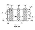
- Figs. 6A and 6B show views of a fluid bed reformer 600 having vertically spaced apart clusters of heating conduits with feedstock being injected between the spaced apart clusters.
- Fluid bed reformer 600 comprises a compartment 601 serving as a reaction vessel 602.
- the reaction vessel 602 has a rectangular footprint (i.e., a rectangular shape in a horizontal cross-section) comprising two long sides 604A, 604B and two short sides 606A, 606B.
- a plurality of pulse heaters 608A, 608B pass through the long sides 604A, 604B of the reformer vessel 600.
- the pulse heaters 608A, 608B are of a sort well known to those skilled in the art, such as those disclosed in U.S. Patent No. 5,059,404 , mentioned above.
- the resonance tubes 609 associated with these pulse heaters 608A, 608B serve as heating conduits for indirectly heating contents of the compartment 601.
- the pulse heaters 608A, 608B are organized into two vertically spaced-apart clusters, a first, or lower, cluster 610 and a second, or upper, cluster 620.
- each cluster 610, 620 comprises one or more rows of pulse heaters. It is understood, however, that the pulse heaters within a cluster are not required to be arranged in rows, to be in accordance with the present invention.
- the pulse heaters 608A belonging to the lower cluster 610 are arranged in a single, horizontal row 612. Since it is the only row, row 612 serves as both the uppermost row 612 and as the lowermost row 612 of lower cluster 610.
- the vertical extent V1 of the lower cluster 610 is therefore commensurate with the row height R1.
- the row height R1 corresponds to the thickness T1 of a pulse heater 608A belonging to this row 612 (or, more precisely, the thickness T1 of a heating conduit 609 associated with the pulse heater 608A). Therefore, in the case of a cylindrical heating conduit that is arranged horizontally, R1 is simply the heating conduit diameter. While three pulse heaters are shown in this row 612, it is understood that a row may have a different number of pulse heaters instead.
- the pulse heaters 608B belonging to the upper cluster 620 are arranged in a pair of horizontal rows 614A, 614B.
- the rows 614A, 614B of the upper cluster 620 are staggered relative to one another and are vertically spaced apart from each other by an intra-row spacing of V4.
- the upper cluster 620 has a vertical extent V2 which is greater than the vertical extent of V1 of the lower cluster 610, due to the presence of two rows 614A, 614B in upper cluster 620, rather than the single row 612 in the lower cluster 610.
- the lowermost row 614A of the second cluster 602 has a row height R2 which, in the embodiment shown, corresponds to the thickness T2 of the heating conduit associated with the corresponding pulse heaters 608B.
- the row height R2 of lowermost row 614A of the upper cluster 620 is the same as the row height R1 of the uppermost row 612 of the lower cluster 610.
- the first and second clusters 610, 620 are spaced apart by an inter-cluster vertical spacing S1.
- the clusters 610, 620 are spaced sufficiently far apart so that the vertical spacing S1 is at least as large as the smaller of the heating conduit thicknesses T1 and T2.
- the average heating conduit thickness for that cluster is used as the 'heating conduit thickness' for purpose of determining the minimum vertical spacing S1.
- the vertical spacing S1 is at least as large as the smaller of the two vertical extents V1, V2 (i.e., S1 ⁇ min (V1, V2)).
- the vertical spacing S1 is at least twice as large as the smaller of the two vertical extents V1, V2 (i.e., S1 ⁇ 2* min (V1, V2)).
- the pulse heaters 608A, 608B in each cluster were arranged in horizontal rows, and so the row heights R1, R2 were the same as the heating conduit thicknesses T1, T2. It is understood, however, that in other embodiments, the pulse heaters may not be arranged in horizontal rows, but instead may be tilted, or angled, from one wall 604A to the opposite wall 604B. In such case, the row heights would not be the same as the heating conduit thicknesses. It is understood that in still other embodiments, the pulse heaters may not even be arranged in rows at all. In all of these instances, however, the vertical spacing S1 would still be at least as large as the smaller of the heating conduit thicknesses T1 and T2.
- first and second clusters 610, 620 are shown to have an unequal number of rows, it is understood that in some embodiments the two clusters may have an equal numbers of rows, and that this equal number may be 1, 2, 3, or even more. It is further understood that while in the embodiment of Figs. 6A-6B , the rows 614A, 614B of the second cluster 620 have unequal numbers of pulse heaters 608B, adjacent rows within a cluster may instead have equal numbers of pulse heaters 608B. Thus, for example, rows 614A, 614B of second cluster 620 may each have three pulse heaters 608B, the rows still being staggered relative to one another.
- the total number of rows and the total number of pulse heaters 608A, 608B in each row can be modified in any given design to suit the size, feedstock type and feedstock throughput of the steam reformer 600.
- a distributor 622 into which a fluidization medium 635, such as steam, is introduced.
- a fluidization medium 635 such as steam
- the zone 640 provides for good heat and mass transfer and high reactant (steam) concentration and facilitates enhanced char conversion.
- the vertical extent of this zone 640 will depend upon the char reactivity and the reformer operating conditions with the slower the reaction(s) the greater the vertical extent
- feedstock inlets terminate in a region that is vertically between the two clusters 610, 620.
- feedstock is injected into zone 642, which is separated from the primary char reaction zone 640, at a position vertically above the first cluster of pulse heaters and vertically below the second cluster 620 of pulse heaters. It is understood that the feedstock inlets 637 are approximately at the same height and spaced apart along the short sides 606A, 606B of the reformer vessel 602.
- a dense bed region 644 which extends to the top bed line 646.
- a freeboard region 648 occupies the topmost portion of the reformer vessel 602.
- Product gas 649 exits from the freeboard region 648 via cyclones and other equipment (not shown) known to those skilled in the art.
- pulse heaters 608A, 608B of the fluid reformer 600 are under computer control (not shown) so as to vary the firing rate and heat transfer rate to better match the load in the fluid reformer 600 and also enhance reformer turndown.
- the fluid reformer 600 of Figs. 6A and 6B is similar to the prior art fluid reformer 200 seen in Fig. 2 .
- One principal difference, however, is that the pulse heaters 608A, 608B in fluid reformer 600 are arranged into spaced apart clusters 610, 620, whereas the pulse heaters in the prior art fluid reformer 200 all belong to a single cluster.
- a second difference is that, in some embodiments, the feedstock is introduced into the compartment 602 in a region that is above the lowest pulse heaters and, in one embodiment, is introduced in a region that is between the two clusters 610,620.
- Operation of the fluid bed reformer to create a product gas from a carbonaceous material begins with an apparatus of the sort described above. This is followed by introducing a fluidization medium in the compartment, introducing a carbonaceous material into the compartment in a region that is vertically between the first and second clusters, and then controlling a reaction in the reaction vessel such that at least a portion of the carbonaceous material is converted into a product gas in a fluidized bed.
- the reformer may be configured to operate in a turbulent fluidization regime, and the fluidization medium may consist of one from the group of steam, air, enriched air, oxygen, nitrogen, carbon dioxide, recycle product gas, and mixtures thereof.
- reformer 600 contemplates a fluidized bed reformer having a rectangular footprint
- a reformer with a square footprint or a cylindrical footprint may benefit from the present invention, so long as sufficient vertical spacing between the pulse heaters and inlets are provided to introduce the feedstock into this region between clusters of pulse heaters.
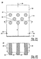
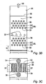
- Fig. 3A shows a side view of a reactor 300 in accordance with another aspect of the present invention.
- the reactor is assumed to be a reformer 300.
- the reformer 300 comprises a reformer vessel 302 and a pair of heat transfer modules 310, 350, one on either side of the reformer vessel 302.
- the reformer vessel 302 defines a compartment 303 configured to receive a fluidizable carbonaceous material.
- two heat transfer modules are vertically offset relative to another.
- the second heat transfer module 350 is at a slightly higher position than the first heat transfer module 310.
- the first heat transfer module 310 includes a first acoustic chamber 311 and a first pulse combustor 312.
- the first pulse combustor 312 includes a pulse combustion chamber 313 connected to a tail pipe 314.
- the pulse combustion chamber 313 is positioned atop the first acoustic chamber 311.
- the tail pipe 314 is substantially entirely within the first acoustic chamber 311 and extends in a vertically downward direction therein.
- the tailpipe exit 316 is positioned about half-way along the vertical extent of the acoustic chamber 311, which has a height of 2 x H3. This allows for the first acoustic chamber 311 to resonate upon activation of the first pulse combustor 312 and result in a standing wave in the acoustic chamber.
- Sitting atop the pulse combustion chamber 313 is an air plenum 318, which surrounds a valve 320.
- the valve may comprise a single valve, or may comprise a multiple valve 320.
- the valve 320 provides a gateway to the inlet of the pulse combustion chamber 313, and thus permits combustibles 322 such as fuel and/or product gas, and air 324, to enter the latter.
- the air 324 may enter the air plenum 318 and mix with the combustibles 322 proximate the exit of the valve 320 before being injected into the pulse combustion chamber 313.
- the combustion products exiting the end 316 of the tail pipe 314 into the first acoustic chamber 311 pass through openings formed in a first wall 332 of the reformer vessel 302 and enter into a plurality of heat transfer tubes 326 connected to the first wall 332.
- the heat transfer tubes 326 belong to either a first upper heat transfer tube bundle 328U or a first lower heat transfer tube bundle 328L.
- the first upper and lower heat transfer tube bundles 328U, 328L protrude into the reformer vessel 302 where heat is imparted into the fluid therein.
- Each bundle 328U, 328L, 368U, 368L comprises a plurality of heat transfer tubes.
- each bundle 328U, 328L may comprise a plurality of rows 330 of tubes 326.
- the rows 330 belonging to a single bundle preferably are staggered, as shown in Fig. 3B , though they may simply be vertically aligned with each other.
- Each row 330 may comprise a plurality of tubes 326, the exact number being limited by the tube diameter, tube spacing and the length L of the vessel wall 332 to which the tubes 326 are connected.
- the total number of rows and the total number of heat transfer tubes 326 can be modified in any given design to suit the size, feedstock type and feedstock throughput of the steam reformer. Once these parameters are known, the first pulse combustor 312 and the first acoustic chamber 311 can be designed to match the heat transfer duty. Since the number of rows and number of columns may be varied, a reformer such as reformer 300 may be scaled from small to large sizes. Regardless of the overall size, the heat transfer tubes 326 can be configured arranged within the reformer vessel 302 to help promote gas-solid contact and mitigate gas/steam channeling and bypassing.
- the first pulse combustor 312 is thus physically separated from the heat transfer tubes 326, but functionally coupled via the first acoustic chamber 311.
- the first acoustic chamber 311 completely encloses the tailpipe 314, with the tailpipe exit 316 located near the geometric center of the acoustic chamber.
- the tailpipe exit 316 corresponds to a velocity anti-node, or pressure node.
- the first acoustic chamber 311 is configured to serve as a standing wave generator with pressure anti-nodes, or velocity nodes, at its ends 311A, 311B.
- the two bundles of heat transfer tubes 328U, 328L are positioned such that the upper bundle 328U is near the pressure anti-node at the top 311A of the first acoustic chamber 311, while the lower bundle 328L is near the pressure anti-node at the bottom 311B of the first acoustic chamber 311.
- This facilitates efficient transfer of the acoustics from the first pulse combustor 312 to the heat transfer tubes 326 of the first upper and lower bundles 328U, 328L. It also provides for periodic boundary layer scrubbing and enhancement in heat transfer coefficient.
- the upper bundles 328U, 368U constitute an upper bundle cluster 329U, while the lower bundles 328L, 368L constitute a lower bundle cluster 329L.
- the lowermost member of the upper bundle cluster 329U is spaced apart from the uppermost member of the lower bundle cluster 329L by an inter-cluster vertical spacing D1.
- the inter-cluster vertical spacing D1 substantially exceeds the inter-row vertical spacing D2, which is the spacing between rows within the bundles.
- the ratio of the inter-cluster vertical spacing D1 to the inter-row vertical spacing D2, D1/D2 is greater than or equal to 2.
- the inter-cluster vertical spacing D1 also exceeds the maximum cluster height D3 of either the upper bundle cluster 329U or the lower bundle cluster 329L, it being understood that the clusters are not required to have the same height, or the same number of rows.
- the ratio of the inter-cluster vertical spacing D1 to the maximum cluster height D3, D1/D3, is greater than or equal to 2. The lower and upper clusters 329L and 329U are all immersed within the dense bed 342.
- the second heat transfer module 350 includes a second acoustic chamber 351 and a second pulse combustor 352.
- the construction of the second pulse combustor 352 is similar to that of the first pulse combustor 312.
- the second pulse combustor 352 thus comprises a pulse combustion chamber 353 connected to a tail pipe 354.
- An air plenum 358 and valve 360 associated with the second pulse combustor 352 for the introduction of combustibles 362 and air 364 are also provided.
- the combustion products exiting the tail pipe 354 into the second acoustic chamber 351 pass through openings formed in a second wall 334 of the reformer vessel 302 and enter into a plurality of heat transfer tubes 366 connected to the second wall 334.
- the heat transfer tubes 366 which preferably are of the same construction as heat transfer tubes 326, belong to either a second upper heat transfer tube bundle 368U or a second lower heat transfer tube bundle 368L.
- the compartment 303 of the reformer vessel 302 includes a number of vertically spaced apart regions having different functional roles and in which various activities take place.
- a distributor 336 into which a fluidization medium 335, such as steam, is introduced.
- the bottommost heat transfer tube 326 is located closer to the distributor 336 to facilitate good communication between the heat source and the heat sink.
- the spacing H4 (see Fig. 3B ) between the distributor 336 and the bottom most heat transfer tube 326 is between 0.5 - 1.5 meters. However, other spacings are possible as well.
- the region above the distributor 336 and below the top of the lower bundles 328L, 368L is termed the enhanced char conversion zone 340.
- the zone 340 provides for good heat and mass transfer and high reactant (steam) concentration and facilitates enhanced char conversion.
- the vertical extent of this zone will depend upon the char reactivity and the reformer operating conditions with the slower the reaction(s) the greater the vertical extent
- a drying and devolatilization zone 342 with height D1 is conducive to good solids circulation, heat transport and gas-solid contact, serves to maximize drying and devolatilization and minimizes tar and char formation.
- a feedstock inlet shown generally as arrow 337 terminates in a region vertically between the lower heat transfer bundles 328L, 368L and the upper heat transfer bundles 328U, 268U.
- feedstock is injected into zone 342, which is separated from the primary char reaction zone 340, at a position vertically above the lower heat transfer bundles 328L, 368L and below the upper heat transfer bundles 328U, 268U.
- this feedstock inlet 337 is intended to represent a plurality of such inlets. This plurality of inlets are all approximately at the same height and are spaced apart along the exposed sides of the vessel 302 that are not in abutment with the acoustic chambers 311, 351, as best seen in Figs. 3B and 3C .
- a dense bed region 344 which extends to the top dense bed line 346.
- a freeboard region 348 occupies the topmost portion of the reformer vessel 302.
- Product gas 349 exits from the topboard region 348 via cyclones and other equipment (not shown) known to those skilled in the art.
- reformer 300 has two heat transfer modules 310, 350, each with an acoustic chamber 311, 351 and an associated pulse combustor 312, 352.
- the two heat transfer modules 310, 350 are under computer control to vary the firing rate and heat transfer rate to better match the load in the reformer 300 and enhance reformer turndown.
- the combustion stoichiometry may be independently adjusted based on the fuel-firing rate to ensure complete combustion in the tailpipes 314, 354 or acoustic chambers 311, 351. Furthermore, tempering air and/or recycle flue gas may be supplied to the acoustic chambers 311, 351 to regulate the temperature of the gases entering the heat transfer tubes 326, 366 and/or minimize pollutant emissions.
- the geometry of the pulse combustors 312, 352 with their associated chambers 313, 353, tailpipes 314, 354 and valves 320, 360 can be designed to maximize combustion and acoustic performance while the heat transfer bundle (shield tube diameter and length, outer tube diameter and length and tube-tube spacing or gap in the bundle) can be designed for optimum heat transfer performance and fluid bed operability.
- the pulse combustors may be operated to provide a controlled amount of heat to the heat transfer tubes to process the reactive material introduced into the reformer vessel 302.
- Persons having ordinary skill in the art of fluid bed operation are familiar with controlling the reformer 300, pulse combustors 312, 352, feedstock, and fluidization medium. Accordingly, through such control, and depending on the material being processed, the reformer 300 may selectively be operated in either the bubbling bed regime or in the turbulent fluidization regime.
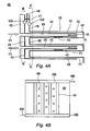
- Fig. 4A shows a cutaway view of a first embodiment of a first wall section 400 belonging to a wall 332 between the first acoustic chamber 311 and the reformer vessel 302.
- the first wall section 400 comprises a tube sheet 406, which may itself comprise a refractory-type material 402 facing the first acoustic chamber 311.
- the wall section 400 comprises a pair of tube sheets 406, 408 which together form an annular membrane wall 404 interrupted by inwardly protruding heat transfer tubes.
- Each heat transfer tube 326, 328 has an annular design, and comprises an inner shield tube 410 and a slightly longer outer tube 412 ("fluid bed heat transfer tube") defining an annulus therebetween.
- the inner tube sheet 406 (which actually is the outermost tube sheet, relative to the reformer vessel 302) supports the inner shield tubes 410 belonging to a bundle.
- the outer tube sheet 408 (which actually is the innermost tube sheet, relative to the reformer vessel 302) supports the outer tubes 412 belonging to a bundle.
- the outer tube sheet 408 is either welded to the vessel wall 332 at predetermined locations, or bolted thereto through a flange connection.
- the inner tube sheet 406 is also flanged and bolted to a decoupler portion adjacent to the vessel wall 332.
- the combustion products such as flue gas emitted from a tailpipe, flow from the acoustic chamber into the inner shield tube 410, as depicted by arrows 413.
- the flue gas first travels in a direction away from the wall 332, along a first channel 409 comprising the hollow center of the inner shield tube 410 and towards the end wall 411 of the heat transfer tube.
- the flue gas then turns around, and flows in a direction towards the wall 332 through a second channel 415 defined by an annulus formed between the inner and other shield tubes 410, 412, as indicated by arrow 414.
- the second channel 415 is in fluid communication with a manifold 416 formed between two tube sheets 406, 408. Therefore, from the second channel 415, the flue gas enters the manifold 416, from whence it is directed towards a flue gas duct 417, as indicated by arrow 418.
- the flue gases therein warm the gases going in the opposite direction within the annular region between inner and outer shield tubes 410, 412, respectively.
- the flue gases in the annulus tend to cool down as they flow from the inlet of the annulus due to heat transfer to the fluid bed, but are somewhat reheated by heat transfer from the flue gases in the inner shield tube 410.
- the shield tube-annulus design promotes near uniform gas temperature on the outer surface of the outer tube 412, thus reducing the potential for local hot spots on the outer tube 412. It also helps enhance heat transfer to the fluid bed within the reformer vessel.
- the cross-section and length of the tubes 410 and 412 are selected such that the heat transfer bundle and the corresponding portion of the acoustic chamber operate as a Helmholtz and/or a quarter wave resonator.
- the tube sheets 406, 408 may be water-cooled, employing a membrane wall construction.
- the outer tube sheet 406 supports an inlet header 420A that is vertically spaced apart from an outlet header 422A. Water 424A is pumped into the inlet header 420A, travels upward through a plurality of cooling tubes 404 and enters the outlet header 422A. A water/steam mixture 426A then exits from this outlet header 422A.
- the inner tube sheet 408 supports an inlet header 420B that is vertically spaced apart from an outlet header 422B. Water 424B is pumped into the inlet header 420B, travels upward through a plurality of cooling tubes 428 and enters the outlet header 422B. A water/steam mixture 426B then exits from this outlet header 422B.
- each acoustic chamber 311, 351 would have two such wall sections associated therewith, two associated with wall 332 and two others associated with wall 334, for a total of four such wall sections in all.
- wall 334 has a similar wall section and so both heat transfer modules 310, 350 pass their flue gases on to the common reaction vessel.
- Fig. 5A shows a cutaway view of a second embodiment of a wall section 500 belonging to a wall 332 between the first acoustic chamber 311 and the reformer vessel 302.
- the wall section 500 comprises a first water jacket 532, which may comprise a refractory-type material 502, facing the acoustic chamber.
- Each of the heat transfer tubes comprises an inner shield tube 510 and a slightly longer outer tube 512 defining an annulus therebetween.
- a pair of water jackets 532, 534 surround the heat transfer tubes.
- First water jacket 532 is formed from a first pair of tube sheets 542A, 542B
- second water jacket 534 is formed from a second pair of tube sheets 544A, 544B.
- the inner shield tube water jacket 532 cools the inner shield tubes 510 of the bundle
- the outer tube water jacket 534 cools the outer tubes 512 of the bundle.
- the water jackets 532, 534 may have a circular face when viewed from the reformer vessel.
- the water jackets may instead have a rectangular face if the steam pressure is relatively low, or if their periphery can be reinforced adequately to comply with the pressure requirements of the reformer vessel.
- the combustion products such as flue gas emitted from a tailpipe
- the flue gas travels along the inner shield tube 510 to its end, turns around, and flows through the outer annulus, as indicated by arrow 514.
- the flue gas then enters a manifold 516 formed between the two water jackets 532, 534. From the manifold, the flue gas is directed towards a flue gas duct 517 as indicated by arrow 518, and from there exits the reformer vessel, as indicated by arrow 519.
- pulse combustors 312, 352 are shown with single valves 320, 360, respectively, and single tailpipes 314, 354, respectively. It is understood, however, that the pulse combustors 312, 352 may each comprise a plurality of such valves and/or a plurality of tailpipes, as necessary.
- the reformer may be configured to operate in a turbulent fluidization regime, and the fluidization medium may consist of one from the group of steam, air, enriched air, oxygen, nitrogen, carbon dioxide, recycle product gas, and mixtures thereof.
- the disclosed reactor 300 may also be gainfully employed for processing any reactive material using thermochemical and/or biochemical approaches.
- Reactive materials that are contemplated here include not only carbonaceous materials, but also inorganics, among others. It is understood that persons having ordinary skill in the art of fluid bed operation are familiar with controlling the reactor, pulse combustors, feedstock inlets and fluidization medium to thermochemically or biochemically process a whole host of different reactive materials.
Landscapes
- Chemical & Material Sciences (AREA)
- Engineering & Computer Science (AREA)
- Combustion & Propulsion (AREA)
- Oil, Petroleum & Natural Gas (AREA)
- Organic Chemistry (AREA)
- Dispersion Chemistry (AREA)
- Mechanical Engineering (AREA)
- General Engineering & Computer Science (AREA)
- Materials Engineering (AREA)
- Devices And Processes Conducted In The Presence Of Fluids And Solid Particles (AREA)
- Fluidized-Bed Combustion And Resonant Combustion (AREA)
- Gasification And Melting Of Waste (AREA)
- Hydrogen, Water And Hydrids (AREA)
- Apparatus Associated With Microorganisms And Enzymes (AREA)
Claims (15)
- Réacteur à lit fluidisé, comprenant :une enceinte de réaction définissant un compartiment configuré pour recevoir un matériau susceptible d'être fluidisé, l'enceinte de réaction ayant au moins une première portion de paroi et une seconde portion de paroi ;un premier module de transfert de chaleur connecté à l'enceinte de réaction, le premier module de transfert de chaleur comprenant un premier dispositif de combustion pulsé connecté à une première chambre acoustique ayant une première extrémité et une seconde extrémité, tel que le premier dispositif de combustion pulsé comprend au moins une première buse d'éjection qui se termine dans la première chambre acoustique entre la première et la seconde extrémité ; etune première pluralité de tubes de transfert de chaleur qui se projettent dans ledit compartiment, chacun de ladite première pluralité de tubes de transfert de chaleur étant en communication fluidique avec la chambre acoustique à travers ladite première portion de paroi,dans lequel :chacun de ladite première pluralité de tubes de transfert de chaleur est configuré de telle façon que les produits de combustion émis depuis ladite au moins une première buse d'éjection circulent le long d'un premier canal de chaque tube de transfert de chaleur dans une direction en éloignement de ladite première portion de paroi, et ensuite le long d'un second canal de chaque tube de transfert de chaleur dans une direction vers la première portion de paroi ; etladite au moins une buse d'éjection comprend un tube résonateur du premier dispositif de combustion pulsé et ne se projette pas dans le compartiment de l'enceinte de réaction.
- Réacteur à lit fluidisé selon la revendication 1, dans lequel :chacun de ladite première pluralité de tubes de transfert de chaleur comprend un tube écran intérieur et un tube extérieur ;le tube écran intérieur forme le premier canal ; etun anneau formé entre le tube écran intérieur et le tube extérieur forme le second canal.
- Réacteur à lit fluidisé selon la revendication 2, comprenant en outre un collecteur en communication fluidique avec le second canal, dans lequel :le collecteur est formé entre une première tôle de tube associée au tube écran intérieur et une seconde tôle de tube associée au tube extérieur.
- Réacteur à lit fluidisé selon la revendication 1, dans lequel :ladite au moins une première buse d'éjection se termine environ à mi-chemin le long de l'extension verticale de la chambre acoustique, entre la première et la seconde extrémité.
- Réacteur à fluidisé selon la revendication 4, dans lequel :lors de l'activation du premier dispositif de combustion pulsé, la première chambre acoustique résonne et une onde stationnaire est créée dans celle-ci avec des ventres de pression formés à ladite première et ladite seconde extrémité.
- Réacteur à fluidisé selon la revendication 1, comprenant en outre un système de refroidissement associé à la première pluralité de tubes de transfert de chaleur, ledit système de refroidissement comprenant un collecteur d'entrée espacé verticalement d'un collecteur de sortie, et une pluralité de tubes de refroidissement entre le collecteur d'entrée et le collecteur de sortie.
- Réacteur à lit fluidisé selon la revendication 1, comprenant en outre un système de refroidissement associé à la première pluralité de tubes de transfert de chaleur, ledit système de refroidissement comprenant une paire de chemises espacées l'une de l'autre, une première chemise refroidissant les tubes intérieurs de la première pluralité de tubes de transfert de chaleur, et une seconde chemise refroidissant des tubes extérieurs de la première pluralité de tubes de transfert de chaleur.
- Réacteur à fluidisé selon la revendication 1, comprenant en outre :une seconde pluralité de tubes de transfert de chaleur se projetant dans ledit compartiment, chacun de ladite seconde pluralité de tubes de transfert de chaleur étant également en communication fluidique avec la première chambre acoustique,la seconde pluralité de tubes de transfert de chaleur étant verticalement espacés de ladite première pluralité de tubes de transfert de chaleur, dans lequel :chacun de ladite seconde pluralité de tubes de transfert de chaleur est configuré de telle façon que les produits de combustion émis depuis la buse d'éjection circulent le long d'un premier canal de chaque tube de transfert de chaleur dans une direction en éloignement de ladite première portion de paroi, et ensuite le long d'un second canal de chacun des tubes de transfert de chaleur dans une direction vers la première portion de paroi.
- Réacteur à fluidisé selon la revendication 8, comprenant en outre au moins une entrée de matières premières en communication fluidique avec ledit compartiment, ladite au moins une entrée de matières premières se terminant dans une région verticalement entre la première et la seconde pluralité de tubes de transfert de chaleur.
- Réacteur à lit fluidisé selon la revendication 8, comprenant en outre :un second module de transfert de chaleur connecté à l'enceinte de réaction, le second module de transfert de chaleur comprenant un second dispositif de combustion pulsé connecté à une seconde chambre acoustique, tel que le second dispositif de combustion pulsée comprend une seconde buse d'éjection qui se termine dans la seconde chambre acoustique, etune troisième pluralité de tubes de transfert de chaleur qui se projettent dans ledit compartiment, chacun de ladite troisième pluralité de tubes de transfert de chaleur étant en communication fluidique avec la seconde chambre acoustique à travers la seconde portion de paroi,dans lequel :chacun de ladite troisième pluralité de tubes de transfert de chaleur est configuré de telle façon que les produits de combustion émis depuis ladite seconde buse d'éjection circulent le long d'un premier canal de chacun de ladite troisième pluralité de tubes de transfert de chaleur dans une direction en éloignement d'une seconde portion de paroi, et ensuite le long d'un second canal de chacun de ladite troisième pluralité de tubes de transfert de chaleur dans une direction vers la seconde portion de paroi.
- Réacteur à lit fluidisé selon la revendication 10, comprenant en outre :une quatrième pluralité de tubes de transfert de chaleur qui se projettent dans ledit compartiment, chacun de ladite quatrième pluralité de tubes de transfert de chaleur étant également en communication fluidique avec la seconde chambre acoustique,la quatrième pluralité de tubes de transfert de chaleur étant verticalement espacés de ladite troisième pluralité de tubes de transfert de chaleur,dans lequel :chacun de ladite quatrième pluralité de tubes de transfert de chaleur est configuré de telle façon que les produits de combustion émis depuis la seconde buse d'éjection circulent le long d'un premier canal de chacun de ladite quatrième pluralité de tubes de transfert de chaleur dans une direction en éloignement de ladite seconde portion de paroi, et ensuite le long d'un second canal de chacun de ladite quatrième pluralité de tubes de transfert de chaleur dans une direction vers la seconde portion de paroi.
- Réacteur à fluidisé selon la revendication 11, comprenant en outre au moins une entrée de matières premières en communication fluidique avec ledit compartiment, ladite au moins une entrée de matières premières se terminant dans une région verticalement entre la première et la seconde pluralité de tubes de transfert de chaleur, et également entre la troisième et la quatrième pluralité de tubes de transfert de chaleur.
- Réacteur à lit fluidisé selon la revendication 1, comprenant :une pluralité de modules de transfert de chaleur connectés à l'enceinte de réaction,chaque module de transfert de chaleur comprenant un dispositif de combustion pulsé connecté à une chambre acoustique associée, tel que chaque dispositif de combustion pulsé comprend au moins une buse d'éjection qui se termine dans la chambre acoustique associée, etune pluralité de tubes de transfert de chaleur supérieurs et inférieurs qui se projettent dans ledit compartiment, chacun de ladite pluralité de tubes de transfert de chaleur supérieurs et inférieurs étant en communication fluidique avec la chambre acoustique associée à travers une portion de paroi de l'enceinte de réaction,dans lequel :chacun de ladite pluralité de tubes de transfert de chaleur supérieurs et inférieurs est configuré de telle façon que les produits de combustion émis depuis ladite au moins une buse d'éjection circulent le long d'un premier canal de chaque tube de transfert de chaleur dans une direction en éloignement de la portion de paroi de l'enceinte de réaction, et ensuite le long d'un second canal de chaque tube de transfert de chaleur dans une direction vers la portion de paroi.
- Réacteur à lit fluidisé, comprenant :une enceinte de réaction définissant un compartiment approprié pour recevoir un matériau réactif ;une pluralité de modules de transfert de chaleur connectés à l'enceinte de réaction,chaque module de transfert de chaleur comprenant un dispositif de combustion pulsé connecté à une chambre acoustique associée ayant une première extrémité et une seconde extrémité, tel que chaque dispositif de combustion pulsé comprend au moins une buse d'éjection qui se termine dans la chambre acoustique associée entre la première et la seconde extrémité, etune pluralité de tubes de transfert de chaleur supérieurs et inférieurs qui se projettent dans ledit compartiment, chacun de ladite pluralité de tubes de transfert de chaleur supérieurs et inférieurs étant en communication fluidique avec la chambre acoustique associée à travers une portion de paroi de l'enceinte de réaction,dans lequel :chacun de ladite pluralité de tubes de transfert de chaleur supérieurs et inférieurs est configuré de telle façon que les produits de combustion émis depuis ladite au moins une buse d'éjection circulent le long d'un premier canal de chaque tube de transfert de chaleur dans une direction en éloignement de la portion de paroi de l'enceinte de réaction, et ensuite le long d'un second canal de chaque tube de transfert de chaleur dans une direction vers la portion de paroi ;ladite au moins une buse d'éjection comprend un tube résonateur du premier dispositif de combustion pulsé et ne se projette pas dans le compartiment de l'enceinte de réaction.
- Réacteur à lit fluidisé selon la revendication 14, comprenant en outre au moins une entrée de matières premières en communication fluidique avec ledit compartiment, ladite au moins une entrée de matières premières se terminant dans une région verticalement entre la pluralité de tubes de transfert de chaleur supérieurs et inférieurs.
Priority Applications (1)
| Application Number | Priority Date | Filing Date | Title |
|---|---|---|---|
| EP11157542.9A EP2343116B1 (fr) | 2006-04-24 | 2007-04-20 | Réacteur à lit fluidisé doté d'un module de transfert de type chambre de combustion pulsatoire |
Applications Claiming Priority (3)
| Application Number | Priority Date | Filing Date | Title |
|---|---|---|---|
| US11/409,837 US7569086B2 (en) | 2006-04-24 | 2006-04-24 | Fluid bed reactor having vertically spaced apart clusters of heating conduits |
| US11/429,917 US7531014B2 (en) | 2006-04-24 | 2006-05-08 | Fluid bed reactor having a pulse combustor-type heat transfer module separated from the compartment of a reaction vessel |
| PCT/US2007/067095 WO2007127679A2 (fr) | 2006-04-24 | 2007-04-20 | Réacteur à lit fluidisé pourvu d'un module de transfert de chaleur de type chambre de combustion pulsatoire |
Related Child Applications (1)
| Application Number | Title | Priority Date | Filing Date |
|---|---|---|---|
| EP11157542.9A Division EP2343116B1 (fr) | 2006-04-24 | 2007-04-20 | Réacteur à lit fluidisé doté d'un module de transfert de type chambre de combustion pulsatoire |
Publications (3)
| Publication Number | Publication Date |
|---|---|
| EP2015864A2 EP2015864A2 (fr) | 2009-01-21 |
| EP2015864A4 EP2015864A4 (fr) | 2010-09-22 |
| EP2015864B1 true EP2015864B1 (fr) | 2011-04-06 |
Family
ID=38618091
Family Applications (2)
| Application Number | Title | Priority Date | Filing Date |
|---|---|---|---|
| EP11157542.9A Active EP2343116B1 (fr) | 2006-04-24 | 2007-04-20 | Réacteur à lit fluidisé doté d'un module de transfert de type chambre de combustion pulsatoire |
| EP07761021A Active EP2015864B1 (fr) | 2006-04-24 | 2007-04-20 | Réacteur à lit fluidisé pourvu d'un module de transfert de chaleur de type chambre de combustion pulsatoire |
Family Applications Before (1)
| Application Number | Title | Priority Date | Filing Date |
|---|---|---|---|
| EP11157542.9A Active EP2343116B1 (fr) | 2006-04-24 | 2007-04-20 | Réacteur à lit fluidisé doté d'un module de transfert de type chambre de combustion pulsatoire |
Country Status (14)
| Country | Link |
|---|---|
| US (1) | US7569086B2 (fr) |
| EP (2) | EP2343116B1 (fr) |
| JP (2) | JP5250546B2 (fr) |
| CN (1) | CN101479026B (fr) |
| AT (1) | ATE504348T1 (fr) |
| AU (1) | AU2007244946B2 (fr) |
| BR (1) | BRPI0710807A2 (fr) |
| CA (1) | CA2650790C (fr) |
| DE (1) | DE602007013743D1 (fr) |
| ES (2) | ES2518494T3 (fr) |
| NZ (1) | NZ572297A (fr) |
| RU (1) | RU2448765C2 (fr) |
| WO (1) | WO2007127679A2 (fr) |
| ZA (1) | ZA200809103B (fr) |
Families Citing this family (46)
| Publication number | Priority date | Publication date | Assignee | Title |
|---|---|---|---|---|
| US7569086B2 (en) * | 2006-04-24 | 2009-08-04 | Thermochem Recovery International, Inc. | Fluid bed reactor having vertically spaced apart clusters of heating conduits |
| CN101293189B (zh) * | 2007-04-25 | 2010-12-08 | 中国科学院过程工程研究所 | 一种用于循环流化床反应器中的扰流型复合构件 |
| EP2438280A4 (fr) | 2009-06-02 | 2014-03-19 | Thermochem Recovery Int Inc | Gazéifieur comprenant un système de génération d'énergie par pile à combustible intégré |
| DE102009039837A1 (de) * | 2009-09-03 | 2011-03-10 | Karl-Heinz Tetzlaff | Elektrische Heizung für einen Wirbelschichtreaktor zur Herstellung von Synthesegas |
| US8487759B2 (en) * | 2009-09-30 | 2013-07-16 | Apple Inc. | Self adapting haptic device |
| US10013058B2 (en) | 2010-09-21 | 2018-07-03 | Apple Inc. | Touch-based user interface with haptic feedback |
| BR112013010886A2 (pt) | 2010-11-05 | 2016-08-02 | Thermochem Recovery Int Inc | sistema de circulação de sólidos e processo para captura e conversão de sólidos reativos |
| US10120446B2 (en) | 2010-11-19 | 2018-11-06 | Apple Inc. | Haptic input device |
| AU2012315914B2 (en) | 2011-09-27 | 2015-07-09 | Thermochem Recovery International, Inc. | System and method for syngas clean-up |
| US11479727B2 (en) | 2011-11-04 | 2022-10-25 | Thermochem Recovery International, Inc. | System and method for flexible conversion of feedstock to oil and gas |
| US9178509B2 (en) | 2012-09-28 | 2015-11-03 | Apple Inc. | Ultra low travel keyboard |
| WO2015020663A1 (fr) | 2013-08-08 | 2015-02-12 | Honessa Development Laboratories Llc | Formes d'onde sculptées avec pas ou peu de réponse non provoquée |
| US9779592B1 (en) | 2013-09-26 | 2017-10-03 | Apple Inc. | Geared haptic feedback element |
| US9928950B2 (en) | 2013-09-27 | 2018-03-27 | Apple Inc. | Polarized magnetic actuators for haptic response |
| HK1222728A1 (zh) | 2013-09-27 | 2017-07-07 | 苹果公司 | 具有觸覺致動器的帶體 |
| US10126817B2 (en) | 2013-09-29 | 2018-11-13 | Apple Inc. | Devices and methods for creating haptic effects |
| WO2015047372A1 (fr) | 2013-09-30 | 2015-04-02 | Pearl Capital Developments Llc | Actionneurs magnétiques pour réponse haptique |
| US9317118B2 (en) | 2013-10-22 | 2016-04-19 | Apple Inc. | Touch surface for simulating materials |
| US10276001B2 (en) | 2013-12-10 | 2019-04-30 | Apple Inc. | Band attachment mechanism with haptic response |
| US9501912B1 (en) | 2014-01-27 | 2016-11-22 | Apple Inc. | Haptic feedback device with a rotating mass of variable eccentricity |
| AU2014391723B2 (en) | 2014-04-21 | 2018-04-05 | Apple Inc. | Apportionment of forces for multi-touch input devices of electronic devices |
| DE102015209639A1 (de) | 2014-06-03 | 2015-12-03 | Apple Inc. | Linearer Aktuator |
| US9830782B2 (en) | 2014-09-02 | 2017-11-28 | Apple Inc. | Haptic notifications |
| US10353467B2 (en) | 2015-03-06 | 2019-07-16 | Apple Inc. | Calibration of haptic devices |
| AU2016100399B4 (en) | 2015-04-17 | 2017-02-02 | Apple Inc. | Contracting and elongating materials for providing input and output for an electronic device |
| CN107925333B (zh) | 2015-09-08 | 2020-10-23 | 苹果公司 | 用于在电子设备中使用的线性致动器 |
| ES2940894T3 (es) | 2016-02-16 | 2023-05-12 | Thermochem Recovery Int Inc | Sistema y método de generación de gas producto de energía integrada de dos etapas |
| US10039080B2 (en) | 2016-03-04 | 2018-07-31 | Apple Inc. | Situationally-aware alerts |
| EP3433340B1 (fr) | 2016-03-25 | 2022-06-29 | ThermoChem Recovery International, Inc. | Système de génération de produit gazeux intégré en énergie à trois étapes |
| US10268272B2 (en) | 2016-03-31 | 2019-04-23 | Apple Inc. | Dampening mechanical modes of a haptic actuator using a delay |
| US10364398B2 (en) | 2016-08-30 | 2019-07-30 | Thermochem Recovery International, Inc. | Method of producing product gas from multiple carbonaceous feedstock streams mixed with a reduced-pressure mixing gas |
| US9920926B1 (en) | 2017-07-10 | 2018-03-20 | Thermochem Recovery International, Inc. | Pulse combustion heat exchanger system and method |
| US10622538B2 (en) | 2017-07-18 | 2020-04-14 | Apple Inc. | Techniques for providing a haptic output and sensing a haptic input using a piezoelectric body |
| US10099200B1 (en) | 2017-10-24 | 2018-10-16 | Thermochem Recovery International, Inc. | Liquid fuel production system having parallel product gas generation |
| US10691211B2 (en) | 2018-09-28 | 2020-06-23 | Apple Inc. | Button providing force sensing and/or haptic output |
| US10599223B1 (en) | 2018-09-28 | 2020-03-24 | Apple Inc. | Button providing force sensing and/or haptic output |
| US11380470B2 (en) | 2019-09-24 | 2022-07-05 | Apple Inc. | Methods to control force in reluctance actuators based on flux related parameters |
| WO2021067379A1 (fr) * | 2019-10-01 | 2021-04-08 | Dow Silicones Corporation | Réacteur de condensation thermique |
| CN110938474B (zh) * | 2019-12-17 | 2021-10-26 | 新奥科技发展有限公司 | 煤样负载造纸黑液的方法、流化床炉以及系统 |
| US11555157B2 (en) | 2020-03-10 | 2023-01-17 | Thermochem Recovery International, Inc. | System and method for liquid fuel production from carbonaceous materials using recycled conditioned syngas |
| EP4118061A4 (fr) * | 2020-03-13 | 2024-04-03 | University of Maryland, College Park | Chauffage par choc à haute température pour des réactions thermochimiques |
| EP3901519A1 (fr) * | 2020-04-20 | 2021-10-27 | Piroenerg - Energias Alternativas, Lda | Dispositif à lit fluidisé et méthode de fonctionnement |
| CN112117476A (zh) * | 2020-07-13 | 2020-12-22 | 东南大学 | 一种分布式生物质气化发电一体化的方法及装置 |
| US11466223B2 (en) | 2020-09-04 | 2022-10-11 | Thermochem Recovery International, Inc. | Two-stage syngas production with separate char and product gas inputs into the second stage |
| US11977683B2 (en) | 2021-03-12 | 2024-05-07 | Apple Inc. | Modular systems configured to provide localized haptic feedback using inertial actuators |
| US11809631B2 (en) | 2021-09-21 | 2023-11-07 | Apple Inc. | Reluctance haptic engine for an electronic device |
Family Cites Families (30)
| Publication number | Priority date | Publication date | Assignee | Title |
|---|---|---|---|---|
| US2800307A (en) | 1954-06-04 | 1957-07-23 | Stratford Eng Corp | Apparatus for controlling temperature change of blends of fluids or fluids and finely divided solids |
| JPS6093211A (ja) * | 1983-10-28 | 1985-05-25 | Toshiba Corp | パルス燃焼装置 |
| US4688521A (en) * | 1986-05-29 | 1987-08-25 | Donlee Technologies Inc. | Two stage circulating fluidized bed reactor and method of operating the reactor |
| DE3635215A1 (de) * | 1986-10-16 | 1988-04-28 | Bergwerksverband Gmbh | Verfahren zur allothermen kohlevergasung und wirbelbett-gasgenerator zur durchfuehrung des verfahrens |
| US5059404A (en) | 1989-02-14 | 1991-10-22 | Manufacturing And Technology Conversion International, Inc. | Indirectly heated thermochemical reactor apparatus and processes |
| US5255634A (en) | 1991-04-22 | 1993-10-26 | Manufacturing And Technology Conversion International, Inc. | Pulsed atmospheric fluidized bed combustor apparatus |
| US5133297A (en) | 1991-04-22 | 1992-07-28 | Manufacturing And Technology Conversion International, Inc. | Pulsed atmospheric fluidized bed combustor apparatus and process |
| US5536488A (en) | 1991-07-01 | 1996-07-16 | Manufacturing And Technology Conversion | Indirectly heated thermochemical reactor processes |
| US5197399A (en) | 1991-07-15 | 1993-03-30 | Manufacturing & Technology Conversion International, Inc. | Pulse combusted acoustic agglomeration apparatus and process |
| US5211704A (en) | 1991-07-15 | 1993-05-18 | Manufacturing Technology And Conversion International, Inc. | Process and apparatus for heating fluids employing a pulse combustor |
| US5353721A (en) | 1991-07-15 | 1994-10-11 | Manufacturing And Technology Conversion International | Pulse combusted acoustic agglomeration apparatus and process |
| US5205728A (en) | 1991-11-18 | 1993-04-27 | Manufacturing And Technology Conversion International | Process and apparatus utilizing a pulse combustor for atomizing liquids and slurries |
| TW245651B (en) * | 1994-02-24 | 1995-04-21 | Babcock & Wilcox Co | Black liquor gasifier |
| US5408115A (en) * | 1994-04-04 | 1995-04-18 | Motorola Inc. | Self-aligned, split-gate EEPROM device |
| US5638609A (en) | 1995-11-13 | 1997-06-17 | Manufacturing And Technology Conversion International, Inc. | Process and apparatus for drying and heating |
| KR20000029664A (ko) * | 1996-08-01 | 2000-05-25 | 칼 하인쯔 호르닝어 | 메모리셀장치의작동방법 |
| JP2000297905A (ja) * | 1999-04-14 | 2000-10-24 | Aichi Mach Ind Co Ltd | パルス燃焼装置 |
| US6469935B2 (en) * | 1999-08-05 | 2002-10-22 | Halo Lsi Design & Device Technology, Inc. | Array architecture nonvolatile memory and its operation methods |
| US6255166B1 (en) * | 1999-08-05 | 2001-07-03 | Aalo Lsi Design & Device Technology, Inc. | Nonvolatile memory cell, method of programming the same and nonvolatile memory array |
| AU7062200A (en) | 1999-08-19 | 2001-03-13 | Manufacturing And Technology Conversion International, Inc. | Gas turbine with indirectly heated steam reforming system |
| EP1216287B1 (fr) | 1999-08-19 | 2005-11-23 | Manufacturing And Technology Conversion International, Inc. | Integration systeme d'un reformeur a vapeur et d'une pile a combustible |
| US6356482B1 (en) * | 2000-02-24 | 2002-03-12 | Advanced Micro Devices, Inc. | Using negative gate erase voltage to simultaneously erase two bits from a non-volatile memory cell with an oxide-nitride-oxide (ONO) gate structure |
| US6531350B2 (en) * | 2001-02-22 | 2003-03-11 | Halo, Inc. | Twin MONOS cell fabrication method and array organization |
| US6756271B1 (en) * | 2002-03-12 | 2004-06-29 | Halo Lsi, Inc. | Simplified twin monos fabrication method with three extra masks to standard CMOS |
| US6498377B1 (en) * | 2002-03-21 | 2002-12-24 | Macronix International, Co., Ltd. | SONOS component having high dielectric property |
| CN1685035A (zh) | 2002-05-22 | 2005-10-19 | 制造及技术转化国际公司 | 脉冲气化和热气净化装置和方法 |
| US6958136B2 (en) | 2003-04-21 | 2005-10-25 | Manufacturing And Technology Conversion International, Inc. | Process for the treatment of waste streams |
| WO2005019749A2 (fr) * | 2003-08-11 | 2005-03-03 | Manufacturing And Technology Conversion International, Inc. | Sechage efficace et rentable de la biomasse |
| JP2005330370A (ja) * | 2004-05-19 | 2005-12-02 | Takuma Co Ltd | 間接加熱式流動床ガス化装置 |
| US7569086B2 (en) * | 2006-04-24 | 2009-08-04 | Thermochem Recovery International, Inc. | Fluid bed reactor having vertically spaced apart clusters of heating conduits |
-
2006
- 2006-04-24 US US11/409,837 patent/US7569086B2/en active Active
-
2007
- 2007-04-20 JP JP2009507906A patent/JP5250546B2/ja active Active
- 2007-04-20 ES ES11157542.9T patent/ES2518494T3/es active Active
- 2007-04-20 ES ES07761021T patent/ES2363613T3/es active Active
- 2007-04-20 AT AT07761021T patent/ATE504348T1/de not_active IP Right Cessation
- 2007-04-20 AU AU2007244946A patent/AU2007244946B2/en not_active Ceased
- 2007-04-20 ZA ZA200809103A patent/ZA200809103B/xx unknown
- 2007-04-20 RU RU2008146061/05A patent/RU2448765C2/ru not_active IP Right Cessation
- 2007-04-20 BR BRPI0710807-9A patent/BRPI0710807A2/pt active Search and Examination
- 2007-04-20 CA CA2650790A patent/CA2650790C/fr active Active
- 2007-04-20 EP EP11157542.9A patent/EP2343116B1/fr active Active
- 2007-04-20 CN CN2007800236205A patent/CN101479026B/zh active Active
- 2007-04-20 EP EP07761021A patent/EP2015864B1/fr active Active
- 2007-04-20 WO PCT/US2007/067095 patent/WO2007127679A2/fr not_active Ceased
- 2007-04-20 NZ NZ572297A patent/NZ572297A/en not_active IP Right Cessation
- 2007-04-20 DE DE602007013743T patent/DE602007013743D1/de active Active
-
2013
- 2013-04-15 JP JP2013085060A patent/JP5843806B2/ja active Active
Also Published As
| Publication number | Publication date |
|---|---|
| JP2009534628A (ja) | 2009-09-24 |
| JP5250546B2 (ja) | 2013-07-31 |
| EP2015864A4 (fr) | 2010-09-22 |
| NZ572297A (en) | 2011-11-25 |
| ES2518494T3 (es) | 2014-11-05 |
| BRPI0710807A2 (pt) | 2011-08-16 |
| ZA200809103B (en) | 2010-01-27 |
| AU2007244946B2 (en) | 2011-08-25 |
| CN101479026B (zh) | 2012-03-14 |
| CA2650790C (fr) | 2015-11-24 |
| AU2007244946A1 (en) | 2007-11-08 |
| ATE504348T1 (de) | 2011-04-15 |
| RU2008146061A (ru) | 2010-05-27 |
| WO2007127679A3 (fr) | 2008-10-16 |
| CA2650790A1 (fr) | 2007-11-08 |
| WO2007127679A9 (fr) | 2009-02-05 |
| EP2343116B1 (fr) | 2014-07-23 |
| WO2007127679A2 (fr) | 2007-11-08 |
| RU2448765C2 (ru) | 2012-04-27 |
| US20070245627A1 (en) | 2007-10-25 |
| JP2013224427A (ja) | 2013-10-31 |
| ES2363613T3 (es) | 2011-08-10 |
| JP5843806B2 (ja) | 2016-01-13 |
| EP2343116A1 (fr) | 2011-07-13 |
| EP2015864A2 (fr) | 2009-01-21 |
| US7569086B2 (en) | 2009-08-04 |
| DE602007013743D1 (de) | 2011-05-19 |
| CN101479026A (zh) | 2009-07-08 |
Similar Documents
| Publication | Publication Date | Title |
|---|---|---|
| EP2015864B1 (fr) | Réacteur à lit fluidisé pourvu d'un module de transfert de chaleur de type chambre de combustion pulsatoire | |
| US7531014B2 (en) | Fluid bed reactor having a pulse combustor-type heat transfer module separated from the compartment of a reaction vessel | |
| EP1148939B1 (fr) | Installation de reformage de gaz combustible d'hydrocarbure pour centrale a piles a combustible | |
| US20030101651A1 (en) | Endothermic reaction process and an apparatus therefor | |
| CZ20014156A3 (cs) | Zařízení pro zplyňování uhlíkatého vsázkového materiálu | |
| CA2127742C (fr) | Chambre de combustion en lit fluidise poreux, chauffee au gaz | |
| EP1193219B1 (fr) | Dispositif et procédé pour le reformage d' hydrocarbure | |
| US6241875B1 (en) | Method of providing heat | |
| JP2007526433A (ja) | 複数の管の配列を有する熱交換器 | |
| JP2001527501A (ja) | 接触式改質装置用バーナーの排気ガス捕集アセンブリ | |
| JP5256802B2 (ja) | ガス化設備のガス化炉構造 | |
| AU2011253687B2 (en) | Fluid bed reactor having a pulse combustor-type heat transfer module | |
| JPH0324401B2 (fr) | ||
| SU1386285A1 (ru) | Печь каталитической конверсии углеводородов | |
| SU902802A1 (ru) | Аппарат с псевдоожиженным слоем |
Legal Events
| Date | Code | Title | Description |
|---|---|---|---|
| PUAI | Public reference made under article 153(3) epc to a published international application that has entered the european phase |
Free format text: ORIGINAL CODE: 0009012 |
|
| 17P | Request for examination filed |
Effective date: 20081112 |
|
| AK | Designated contracting states |
Kind code of ref document: A2 Designated state(s): AT BE BG CH CY CZ DE DK EE ES FI FR GB GR HU IE IS IT LI LT LU LV MC MT NL PL PT RO SE SI SK TR |
|
| AX | Request for extension of the european patent |
Extension state: AL BA HR MK RS |
|
| A4 | Supplementary search report drawn up and despatched |
Effective date: 20100820 |
|
| GRAP | Despatch of communication of intention to grant a patent |
Free format text: ORIGINAL CODE: EPIDOSNIGR1 |
|
| GRAC | Information related to communication of intention to grant a patent modified |
Free format text: ORIGINAL CODE: EPIDOSCIGR1 |
|
| GRAC | Information related to communication of intention to grant a patent modified |
Free format text: ORIGINAL CODE: EPIDOSCIGR1 |
|
| RIC1 | Information provided on ipc code assigned before grant |
Ipc: F27B 15/16 20060101ALI20101006BHEP Ipc: F27B 15/14 20060101ALI20101006BHEP Ipc: C10J 3/54 20060101ALI20101006BHEP Ipc: C10J 3/46 20060101ALI20101006BHEP Ipc: C01B 3/36 20060101ALI20101006BHEP Ipc: B01J 8/18 20060101ALI20101006BHEP Ipc: B01J 7/00 20060101AFI20101006BHEP Ipc: H01M 8/16 20060101ALI20101006BHEP Ipc: F27B 15/00 20060101ALI20101006BHEP |
|
| GRAS | Grant fee paid |
Free format text: ORIGINAL CODE: EPIDOSNIGR3 |
|
| GRAA | (expected) grant |
Free format text: ORIGINAL CODE: 0009210 |
|
| AK | Designated contracting states |
Kind code of ref document: B1 Designated state(s): AT BE BG CH CY CZ DE DK EE ES FI FR GB GR HU IE IS IT LI LT LU LV MC MT NL PL PT RO SE SI SK TR |
|
| REG | Reference to a national code |
Ref country code: GB Ref legal event code: FG4D |
|
| REG | Reference to a national code |
Ref country code: CH Ref legal event code: EP |
|
| REG | Reference to a national code |
Ref country code: IE Ref legal event code: FG4D |
|
| REF | Corresponds to: |
Ref document number: 602007013743 Country of ref document: DE Date of ref document: 20110519 Kind code of ref document: P |
|
| REG | Reference to a national code |
Ref country code: DE Ref legal event code: R096 Ref document number: 602007013743 Country of ref document: DE Effective date: 20110519 |
|
| REG | Reference to a national code |
Ref country code: SE Ref legal event code: TRGR |
|
| REG | Reference to a national code |
Ref country code: NL Ref legal event code: VDEP Effective date: 20110406 |
|
| REG | Reference to a national code |
Ref country code: ES Ref legal event code: FG2A Ref document number: 2363613 Country of ref document: ES Kind code of ref document: T3 Effective date: 20110810 |
|
| PG25 | Lapsed in a contracting state [announced via postgrant information from national office to epo] |
Ref country code: SI Free format text: LAPSE BECAUSE OF FAILURE TO SUBMIT A TRANSLATION OF THE DESCRIPTION OR TO PAY THE FEE WITHIN THE PRESCRIBED TIME-LIMIT Effective date: 20110406 |
|
| LTIE | Lt: invalidation of european patent or patent extension |
Effective date: 20110406 |
|
| PG25 | Lapsed in a contracting state [announced via postgrant information from national office to epo] |
Ref country code: LT Free format text: LAPSE BECAUSE OF FAILURE TO SUBMIT A TRANSLATION OF THE DESCRIPTION OR TO PAY THE FEE WITHIN THE PRESCRIBED TIME-LIMIT Effective date: 20110406 Ref country code: PT Free format text: LAPSE BECAUSE OF FAILURE TO SUBMIT A TRANSLATION OF THE DESCRIPTION OR TO PAY THE FEE WITHIN THE PRESCRIBED TIME-LIMIT Effective date: 20110808 |
|
| PG25 | Lapsed in a contracting state [announced via postgrant information from national office to epo] |
Ref country code: CY Free format text: LAPSE BECAUSE OF FAILURE TO SUBMIT A TRANSLATION OF THE DESCRIPTION OR TO PAY THE FEE WITHIN THE PRESCRIBED TIME-LIMIT Effective date: 20110406 Ref country code: IS Free format text: LAPSE BECAUSE OF FAILURE TO SUBMIT A TRANSLATION OF THE DESCRIPTION OR TO PAY THE FEE WITHIN THE PRESCRIBED TIME-LIMIT Effective date: 20110806 Ref country code: AT Free format text: LAPSE BECAUSE OF FAILURE TO SUBMIT A TRANSLATION OF THE DESCRIPTION OR TO PAY THE FEE WITHIN THE PRESCRIBED TIME-LIMIT Effective date: 20110406 Ref country code: GR Free format text: LAPSE BECAUSE OF FAILURE TO SUBMIT A TRANSLATION OF THE DESCRIPTION OR TO PAY THE FEE WITHIN THE PRESCRIBED TIME-LIMIT Effective date: 20110707 Ref country code: MC Free format text: LAPSE BECAUSE OF NON-PAYMENT OF DUE FEES Effective date: 20110430 Ref country code: LV Free format text: LAPSE BECAUSE OF FAILURE TO SUBMIT A TRANSLATION OF THE DESCRIPTION OR TO PAY THE FEE WITHIN THE PRESCRIBED TIME-LIMIT Effective date: 20110406 Ref country code: BE Free format text: LAPSE BECAUSE OF FAILURE TO SUBMIT A TRANSLATION OF THE DESCRIPTION OR TO PAY THE FEE WITHIN THE PRESCRIBED TIME-LIMIT Effective date: 20110406 |
|
| REG | Reference to a national code |
Ref country code: CH Ref legal event code: PL |
|
| PG25 | Lapsed in a contracting state [announced via postgrant information from national office to epo] |
Ref country code: MT Free format text: LAPSE BECAUSE OF FAILURE TO SUBMIT A TRANSLATION OF THE DESCRIPTION OR TO PAY THE FEE WITHIN THE PRESCRIBED TIME-LIMIT Effective date: 20110406 Ref country code: NL Free format text: LAPSE BECAUSE OF FAILURE TO SUBMIT A TRANSLATION OF THE DESCRIPTION OR TO PAY THE FEE WITHIN THE PRESCRIBED TIME-LIMIT Effective date: 20110406 |
|
| PG25 | Lapsed in a contracting state [announced via postgrant information from national office to epo] |
Ref country code: EE Free format text: LAPSE BECAUSE OF FAILURE TO SUBMIT A TRANSLATION OF THE DESCRIPTION OR TO PAY THE FEE WITHIN THE PRESCRIBED TIME-LIMIT Effective date: 20110406 Ref country code: CH Free format text: LAPSE BECAUSE OF NON-PAYMENT OF DUE FEES Effective date: 20110430 Ref country code: LI Free format text: LAPSE BECAUSE OF NON-PAYMENT OF DUE FEES Effective date: 20110430 Ref country code: CZ Free format text: LAPSE BECAUSE OF FAILURE TO SUBMIT A TRANSLATION OF THE DESCRIPTION OR TO PAY THE FEE WITHIN THE PRESCRIBED TIME-LIMIT Effective date: 20110406 |
|
| REG | Reference to a national code |
Ref country code: IE Ref legal event code: MM4A |
|
| PLBE | No opposition filed within time limit |
Free format text: ORIGINAL CODE: 0009261 |
|
| STAA | Information on the status of an ep patent application or granted ep patent |
Free format text: STATUS: NO OPPOSITION FILED WITHIN TIME LIMIT |
|
| PG25 | Lapsed in a contracting state [announced via postgrant information from national office to epo] |
Ref country code: RO Free format text: LAPSE BECAUSE OF FAILURE TO SUBMIT A TRANSLATION OF THE DESCRIPTION OR TO PAY THE FEE WITHIN THE PRESCRIBED TIME-LIMIT Effective date: 20110406 Ref country code: PL Free format text: LAPSE BECAUSE OF FAILURE TO SUBMIT A TRANSLATION OF THE DESCRIPTION OR TO PAY THE FEE WITHIN THE PRESCRIBED TIME-LIMIT Effective date: 20110406 Ref country code: SK Free format text: LAPSE BECAUSE OF FAILURE TO SUBMIT A TRANSLATION OF THE DESCRIPTION OR TO PAY THE FEE WITHIN THE PRESCRIBED TIME-LIMIT Effective date: 20110406 Ref country code: DK Free format text: LAPSE BECAUSE OF FAILURE TO SUBMIT A TRANSLATION OF THE DESCRIPTION OR TO PAY THE FEE WITHIN THE PRESCRIBED TIME-LIMIT Effective date: 20110406 |
|
| 26N | No opposition filed |
Effective date: 20120110 |
|
| PG25 | Lapsed in a contracting state [announced via postgrant information from national office to epo] |
Ref country code: IE Free format text: LAPSE BECAUSE OF NON-PAYMENT OF DUE FEES Effective date: 20110420 |
|
| REG | Reference to a national code |
Ref country code: DE Ref legal event code: R097 Ref document number: 602007013743 Country of ref document: DE Effective date: 20120110 |
|
| PG25 | Lapsed in a contracting state [announced via postgrant information from national office to epo] |
Ref country code: LU Free format text: LAPSE BECAUSE OF NON-PAYMENT OF DUE FEES Effective date: 20110420 |
|
| PG25 | Lapsed in a contracting state [announced via postgrant information from national office to epo] |
Ref country code: BG Free format text: LAPSE BECAUSE OF FAILURE TO SUBMIT A TRANSLATION OF THE DESCRIPTION OR TO PAY THE FEE WITHIN THE PRESCRIBED TIME-LIMIT Effective date: 20110706 |
|
| PG25 | Lapsed in a contracting state [announced via postgrant information from national office to epo] |
Ref country code: TR Free format text: LAPSE BECAUSE OF FAILURE TO SUBMIT A TRANSLATION OF THE DESCRIPTION OR TO PAY THE FEE WITHIN THE PRESCRIBED TIME-LIMIT Effective date: 20110406 |
|
| PG25 | Lapsed in a contracting state [announced via postgrant information from national office to epo] |
Ref country code: HU Free format text: LAPSE BECAUSE OF FAILURE TO SUBMIT A TRANSLATION OF THE DESCRIPTION OR TO PAY THE FEE WITHIN THE PRESCRIBED TIME-LIMIT Effective date: 20110406 |
|
| PG25 | Lapsed in a contracting state [announced via postgrant information from national office to epo] |
Ref country code: IT Free format text: LAPSE BECAUSE OF FAILURE TO SUBMIT A TRANSLATION OF THE DESCRIPTION OR TO PAY THE FEE WITHIN THE PRESCRIBED TIME-LIMIT Effective date: 20110406 |
|
| REG | Reference to a national code |
Ref country code: DE Ref legal event code: R082 Ref document number: 602007013743 Country of ref document: DE Representative=s name: FRIESE GOEDEN PATENTANWAELTE PARTGMBB, DE Ref country code: DE Ref legal event code: R082 Ref document number: 602007013743 Country of ref document: DE Representative=s name: ANDRAE WESTENDORP PATENTANWAELTE PARTNERSCHAFT, DE |
|
| PGFP | Annual fee paid to national office [announced via postgrant information from national office to epo] |
Ref country code: FI Payment date: 20150429 Year of fee payment: 9 Ref country code: SE Payment date: 20150429 Year of fee payment: 9 |
|
| REG | Reference to a national code |
Ref country code: FR Ref legal event code: PLFP Year of fee payment: 10 |
|
| REG | Reference to a national code |
Ref country code: SE Ref legal event code: EUG |
|
| REG | Reference to a national code |
Ref country code: DE Ref legal event code: R082 Ref document number: 602007013743 Country of ref document: DE Representative=s name: FRIESE GOEDEN PATENTANWAELTE PARTGMBB, DE |
|
| PG25 | Lapsed in a contracting state [announced via postgrant information from national office to epo] |
Ref country code: FI Free format text: LAPSE BECAUSE OF NON-PAYMENT OF DUE FEES Effective date: 20160420 |
|
| PG25 | Lapsed in a contracting state [announced via postgrant information from national office to epo] |
Ref country code: SE Free format text: LAPSE BECAUSE OF NON-PAYMENT OF DUE FEES Effective date: 20160421 |
|
| REG | Reference to a national code |
Ref country code: FR Ref legal event code: PLFP Year of fee payment: 11 |
|
| REG | Reference to a national code |
Ref country code: FR Ref legal event code: PLFP Year of fee payment: 12 |
|
| P01 | Opt-out of the competence of the unified patent court (upc) registered |
Effective date: 20230427 |
|
| PGFP | Annual fee paid to national office [announced via postgrant information from national office to epo] |
Ref country code: DE Payment date: 20251010 Year of fee payment: 19 |
|
| PGFP | Annual fee paid to national office [announced via postgrant information from national office to epo] |
Ref country code: GB Payment date: 20251009 Year of fee payment: 19 |
|
| PGFP | Annual fee paid to national office [announced via postgrant information from national office to epo] |
Ref country code: FR Payment date: 20251009 Year of fee payment: 19 |
|
| PGFP | Annual fee paid to national office [announced via postgrant information from national office to epo] |
Ref country code: ES Payment date: 20251029 Year of fee payment: 19 |