EP2015885B1 - Schneideinsatz mit ausgesparten ecken - Google Patents
Schneideinsatz mit ausgesparten ecken Download PDFInfo
- Publication number
- EP2015885B1 EP2015885B1 EP07756152.0A EP07756152A EP2015885B1 EP 2015885 B1 EP2015885 B1 EP 2015885B1 EP 07756152 A EP07756152 A EP 07756152A EP 2015885 B1 EP2015885 B1 EP 2015885B1
- Authority
- EP
- European Patent Office
- Prior art keywords
- cutting
- cutting insert
- rake face
- insert according
- corner
- Prior art date
- Legal status (The legal status is an assumption and is not a legal conclusion. Google has not performed a legal analysis and makes no representation as to the accuracy of the status listed.)
- Active
Links
Images



Classifications
-
- B—PERFORMING OPERATIONS; TRANSPORTING
- B23—MACHINE TOOLS; METAL-WORKING NOT OTHERWISE PROVIDED FOR
- B23C—MILLING
- B23C5/00—Milling-cutters
- B23C5/16—Milling-cutters characterised by physical features other than shape
- B23C5/20—Milling-cutters characterised by physical features other than shape with removable cutter bits or teeth or cutting inserts
- B23C5/202—Plate-like cutting inserts with special form
- B23C5/205—Plate-like cutting inserts with special form characterised by chip-breakers of special form
-
- B—PERFORMING OPERATIONS; TRANSPORTING
- B23—MACHINE TOOLS; METAL-WORKING NOT OTHERWISE PROVIDED FOR
- B23C—MILLING
- B23C5/00—Milling-cutters
- B23C5/16—Milling-cutters characterised by physical features other than shape
- B23C5/20—Milling-cutters characterised by physical features other than shape with removable cutter bits or teeth or cutting inserts
- B23C5/202—Plate-like cutting inserts with special form
-
- B—PERFORMING OPERATIONS; TRANSPORTING
- B23—MACHINE TOOLS; METAL-WORKING NOT OTHERWISE PROVIDED FOR
- B23C—MILLING
- B23C2200/00—Details of milling cutting inserts
- B23C2200/20—Top or side views of the cutting edge
- B23C2200/201—Details of the nose radius and immediately surrounding areas
-
- B—PERFORMING OPERATIONS; TRANSPORTING
- B23—MACHINE TOOLS; METAL-WORKING NOT OTHERWISE PROVIDED FOR
- B23C—MILLING
- B23C2200/00—Details of milling cutting inserts
- B23C2200/20—Top or side views of the cutting edge
- B23C2200/203—Curved cutting edges
-
- B—PERFORMING OPERATIONS; TRANSPORTING
- B23—MACHINE TOOLS; METAL-WORKING NOT OTHERWISE PROVIDED FOR
- B23C—MILLING
- B23C2200/00—Details of milling cutting inserts
- B23C2200/20—Top or side views of the cutting edge
- B23C2200/205—Discontinuous cutting edges
-
- B—PERFORMING OPERATIONS; TRANSPORTING
- B23—MACHINE TOOLS; METAL-WORKING NOT OTHERWISE PROVIDED FOR
- B23C—MILLING
- B23C2200/00—Details of milling cutting inserts
- B23C2200/28—Angles
- B23C2200/287—Positive rake angles
-
- Y—GENERAL TAGGING OF NEW TECHNOLOGICAL DEVELOPMENTS; GENERAL TAGGING OF CROSS-SECTIONAL TECHNOLOGIES SPANNING OVER SEVERAL SECTIONS OF THE IPC; TECHNICAL SUBJECTS COVERED BY FORMER USPC CROSS-REFERENCE ART COLLECTIONS [XRACs] AND DIGESTS
- Y10—TECHNICAL SUBJECTS COVERED BY FORMER USPC
- Y10T—TECHNICAL SUBJECTS COVERED BY FORMER US CLASSIFICATION
- Y10T407/00—Cutters, for shaping
- Y10T407/19—Rotary cutting tool
- Y10T407/1906—Rotary cutting tool including holder [i.e., head] having seat for inserted tool
- Y10T407/1908—Face or end mill
- Y10T407/1924—Specified tool shape
-
- Y—GENERAL TAGGING OF NEW TECHNOLOGICAL DEVELOPMENTS; GENERAL TAGGING OF CROSS-SECTIONAL TECHNOLOGIES SPANNING OVER SEVERAL SECTIONS OF THE IPC; TECHNICAL SUBJECTS COVERED BY FORMER USPC CROSS-REFERENCE ART COLLECTIONS [XRACs] AND DIGESTS
- Y10—TECHNICAL SUBJECTS COVERED BY FORMER USPC
- Y10T—TECHNICAL SUBJECTS COVERED BY FORMER US CLASSIFICATION
- Y10T407/00—Cutters, for shaping
- Y10T407/23—Cutters, for shaping including tool having plural alternatively usable cutting edges
-
- Y—GENERAL TAGGING OF NEW TECHNOLOGICAL DEVELOPMENTS; GENERAL TAGGING OF CROSS-SECTIONAL TECHNOLOGIES SPANNING OVER SEVERAL SECTIONS OF THE IPC; TECHNICAL SUBJECTS COVERED BY FORMER USPC CROSS-REFERENCE ART COLLECTIONS [XRACs] AND DIGESTS
- Y10—TECHNICAL SUBJECTS COVERED BY FORMER USPC
- Y10T—TECHNICAL SUBJECTS COVERED BY FORMER US CLASSIFICATION
- Y10T407/00—Cutters, for shaping
- Y10T407/24—Cutters, for shaping with chip breaker, guide or deflector
- Y10T407/245—Cutters, for shaping with chip breaker, guide or deflector comprising concave surface in cutting face of tool
Definitions
- the present invention relates, in general, to a cutting insert used in metalworking operations and, more particularly, to chip flow control features on a cutting insert.
- Cutting inserts are well known and a large percentage of them are of the throw away design. Such inserts are detachably clamped on a toolholder and then are discarded when they become dull or chipped. Throw away inserts are usually indexable and/or invertable so that an insert can be provided with at least two cutting edges for selective presentation to the cutting position. An indexable and/or invertable insert having multiple cutting edges is more economical because when one edge has been used, the insert may simply be indexed or inverted to the next usable edge. Such a feature is especially important when considering the high cost of materials from which inserts are produced.
- the main object of metalworking is the shaping of a new work surface. Much attention is paid to the formation of the chip during the machining process, even though the chip is a waste product, because the consumption of energy occurs mainly in the formation and movement of the chip. Thus, an essential feature of any metalworking operation is effective chip flow.
- United States Patent No. 6,769,844 entitled “Cutting Insert and Method of Making the Same” teaches a cutting insert with a convex wiper cutting edge with a chamfered corner provided between the cutting edges.
- chip flow control is an important consideration in metal cutting operations, it has been a long standing objective in the art of metal cutting to develop improved chip flow control surfaces for use with cutting inserts.
- a cutting insert is provided as defined in claim1.
- the insert comprises a rake face, a seating surface and a plurality of flank faces extending between the rake face and the seating surface.
- the intersection of the rake face and the plurality of flank faces define a plurality of side cutting edges.
- the rake face of the body has a plurality of corner regions formed at the intersection of side cutting edges to define corner cutting edges.
- the corner cutting edge in at least One corner region has a recessed profile when viewed from the side of the insert.
- the recessed profile has a concave shape and extends inwardly from the cutting edge.
- the recess preferably has a conical shaoe to define a conical portion and further inward from the cutting edge the recess may have a cylindrical shape to define a cylindrical portion.
- a cutting insert 10 has a body 15, comprised of a rake face 20 and a seating surface 25.
- a plurality of flank surfaces 30a-30d extends between the rake face 20 and the seating surface 25.
- a plurality of side cutting edges 35a-35d are defined by the intersection of the rake face 20 and the plurality of flank faces 30a-30d.
- the rake face 20 has a plurality of corner regions 40a-40d formed at the intersection of the side cutting edges 35a-35d to define corner cutting edges 45a-45d.
- the body 15 has a substantially square shape.
- this is not to be construed as limiting as a variety of other cutting geometries for cutting insert 10 have been envisioned, including octagonal and pentagonal.
- each of the cutting edges described herein can be indexed into a working or active position and effectively utilized in a cutting tool of a type well know in the art.
- One particular use for this cutting insert 10 may be with a plunge milling cutter.
- corner region 40a will hereinafter be discussed with the understanding that such details may be applied to the remaining corner regions 40b-40d of the insert 10.
- the corner cutting edge 45a in the corner region 40a has a recessed profile 50a when viewed from the side of the body 15.
- the recessed profile 50a has a concave shape.
- the recessed profile 50a extends inwardly from the corner cutting edge 45a.
- the recessed profile 50a extends inwardly and into the rake face 20 from the corner cutting edge 45a.
- the recessed profile 50a has a conical shape to define a conical portion 55a.
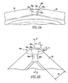
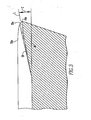
- the conical portion 55a extends inwardly from the comer cutting edge 45a a distance "A" of (0.51 to 0.76 mm 0.02-0.030 inches) and preferably is in the range of 0.13 to 0.15 mm (0.005-0.006 inches). Additionally, directing attention to FIG. 2B , the conical portion 55a may have a cone angle "B" of between about 5-45 degrees with a preferred angle of about 20 degrees. As illustrated in FIG. 3 , the central axis L of the cone may form an angle "C" with a line 26 parallel with the seating surface 25 of the body 15 of between about 2-30 degrees and preferably between about 5-10 degrees.
- the recessed profile 50a extends inwardly over the entire width W of the rake face 20.
- the recessed profile 50a may include a cylindrical portion 60a recessed within the rake face 20 and located inwardly of the conical portion 55a.
- a blending portion 65a may connect the conical portion 55a with the cylindrical portion 60a to provide for a smooth transition between these portions.
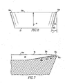
- the cutting edges 35a, 35b, for example, adjacent to the corner region 40a may be straight or convex when viewed from the side as illustrated in FIG. 6 .
- cutting edge 35a as illustrated in FIG. 6 may have a radius of curvature R of approximately 20.3 cm (8 inches).
- the rake face 20 may also have a convex profile as it extends inwardly from the cutting edge 35a.
- the recessed profile 50a extends inwardly from the corner cutting edge 45a into the rake face 20.
- the recessed portion 50a continues inwardly from the cutting edge 45a with the conical portion 55a extending into the rake face 20.
- the recessed profile 50a continues to extend inwardly to the blending portion 65a and into the cylindrical portion 60a.
- the cutting edge 45a follows the cutting edge 35 and causes the cutting chip to lift and flow away from the workpiece.
- each flank face for example flank face 30d, is substantially flat and forms a clearance angle "F" of between about 0-30 degrees, preferably about 11-20 degrees, with a line perpendicular to the generally planar surface defined by the cutting edges 35.
- FIG. 8 shows the cutting insert 10 mounted within a toolholder and machining a workpiece.
- FIG. 8 illustrates the cutting insert 10 mounted within a milling cutter 100.
- the milling cutter 100 is comprised of a body 105 which extends along a longitudinal axis 110 and has a first end 115.
- a recess 120 extends into the first end 115 and has an insert pocket 125 adapted to receive the cutting insert 10.
- the cutting insert 10 may have a bore 80 ( FIG. 4 ) extending therethrough to accommodate a mounting screw 132 which may be threadably engaged within a threaded bore (not shown) extending through a floor in the pocket 125 of the recess 120.
- the milling cutter 100 may be rotated about longitudinal axis 110 in a clockwise direction such that the cutting insert 10 engages the workpiece 130 to form the workpiece 130 in the desired shape.
Landscapes
- Engineering & Computer Science (AREA)
- Mechanical Engineering (AREA)
- Cutting Tools, Boring Holders, And Turrets (AREA)
- Milling Processes (AREA)
Claims (15)
- Schneideeinsatz, umfassend einen Körper (15) mit einer Spanfläche (20), eine Aufnahmefläche (25) und eine Vielzahl von Flankenflächen (30a-30d), die sich zwischen der Spanfläche (20) und der Aufnahmefläche (25) erstrecken,
wobei die Schnittstelle der Spanfläche (20) und der Vielzahl von Flankenflächen (30a-30d) eine Vielzahl von seitlichen Schneidekanten (35a-35d) definiert,
wobei sich die Spanfläche (20) von der Schneidekante (35a) erstreckt, wobei die Spanfläche (20) eine Vielzahl von Eckbereichen (40a-40d) aufweist, die an der Schnittstelle der seitlichen Schneidekanten (35a-35d) gebildet sind, um Eckschneidekanten (45a-45d) zu definieren, wobei die Eckschneidekante (45a) in mindestens einem Eckbereich (40a) ein ausgespartes Profil (50a) aufweist, wenn es von einem Eckbereich (40a) des Einsatzkörpers (15) aus gesehen wird, und
wobei das ausgesparte Profil (50a) eine konkave Form aufweist und sich von der Eckschneidekante (45a) nach innen in die Spanfläche (20) des Einsatzkörpers (15) erstreckt,
dadurch gekennzeichnet, dass die Spanfläche (20) einen positiven Spanwinkel bildet. - Schneideeinsatz nach Anspruch 1, wobei jeder Eckbereich (40a-40d) einen Steg (70) aufweist, der sich von der Eckschneidekante (45a-45d) nach innen erstreckt und das ausgesparte Profil (50a) sich in den Steg (70) erstreckt.
- Schneideeinsatz nach Anspruch 1, wobei das ausgesparte Profil (50a) eine konische Form aufweist, insbesondere eine konische Form, die angeordnet ist, um einen konischen Abschnitt (55a) zu bilden.
- Schneideeinsatz nach Anspruch 3, wobei sich der konische Abschnitt (55a) von der Eckschneidekante (45a) um zwischen 0,51 und 0,76 mm (0,020 und 0,030 Zoll) nach innen erstreckt.
- Schneideeinsatz nach Anspruch 3 oder 4, wobei der konische Abschnitt (55a) einen Kegelwinkel (B) von zwischen 5 und 45 Grad aufweist.
- Schneideeinsatz nach Anspruch 3, 4 oder 5, wobei der konische Abschnitt (55a) eine zentrale Achse (L) aufweist und die zentrale Achse mit der Aufnahmefläche (25) einen Winkel (C) von zwischen 2 und 30 Grad bildet.
- Schneideeinsatz nach einem der Ansprüche 1 bis 6, wobei sich das ausgesparte Profil (50a) über die gesamte Breite (W) der Spanfläche (20) nach innen erstreckt.
- Schneideeinsatz nach einem der Ansprüche 4 bis 7, wobei das ausgesparte Profil (50a) ferner einen zylindrischen Abschnitt (60a) aufweist, der in der Spanfläche (20) vom konischen Abschnitt (55a) nach innen ausgespart ist.
- Schneideeinsatz nach Anspruch 8, ferner umfassend einen Übergangsabschnitt (65a), der den konischen Abschnitt (55a) mit dem zylindrischen Abschnitt (60a) verbindet.
- Schneideeinsatz nach einem der Ansprüche 1 bis 9, wobei die Schneidekanten (35a-35d), die zwischen den Eckabschnitten (40a-40d) gebildet sind, konvex sind, wenn sie von der Seite gesehen werden.
- Schneideeinsatz nach einem der Ansprüche 1 bis 10, wobei die Schneidekanten (35a-35d) gehont sind.
- Schneideeinsatz nach einem der Ansprüche 1 bis 11, wobei der Spanfläche (20) ein konvexes Profil aufweist, wenn sie sich von der Eckschneidekante (45a) nach innen erstreckt.
- Schneideeinsatz nach einem der Ansprüche 1 bis 12, wobei die Flankenflächen (30a-30d) im Wesentlichen flach sind.
- Schneideeinsatz nach einem der Ansprüche 1 bis 13, wobei der Körper (15) eine im Wesentlichen quadratische Form aufweist.
- Schneideeinsatz nach einem der Ansprüche 1 bis 14, ferner aufweisend einen Steg (70) zwischen den Schneidekanten (35a-35d) und der Spanfläche (20).
Applications Claiming Priority (2)
| Application Number | Priority Date | Filing Date | Title |
|---|---|---|---|
| US11/429,822 US7476062B2 (en) | 2006-05-08 | 2006-05-08 | Cutting insert with recessed corners |
| PCT/US2007/010447 WO2007133437A2 (en) | 2006-05-08 | 2007-04-30 | Cutting insert with recessed corners |
Publications (3)
| Publication Number | Publication Date |
|---|---|
| EP2015885A2 EP2015885A2 (de) | 2009-01-21 |
| EP2015885A4 EP2015885A4 (de) | 2010-01-20 |
| EP2015885B1 true EP2015885B1 (de) | 2015-07-29 |
Family
ID=38661302
Family Applications (1)
| Application Number | Title | Priority Date | Filing Date |
|---|---|---|---|
| EP07756152.0A Active EP2015885B1 (de) | 2006-05-08 | 2007-04-30 | Schneideinsatz mit ausgesparten ecken |
Country Status (8)
| Country | Link |
|---|---|
| US (1) | US7476062B2 (de) |
| EP (1) | EP2015885B1 (de) |
| JP (1) | JP5108005B2 (de) |
| KR (1) | KR20090033324A (de) |
| CN (1) | CN101448594B (de) |
| BR (1) | BRPI0711439A2 (de) |
| CA (1) | CA2646479A1 (de) |
| WO (1) | WO2007133437A2 (de) |
Families Citing this family (17)
| Publication number | Priority date | Publication date | Assignee | Title |
|---|---|---|---|---|
| DE102006044605A1 (de) * | 2006-09-19 | 2008-03-27 | Komet Group Holding Gmbh | Wendeschneidplatte sowie Verwendung der Wendeschneidplatte in einem Vollbohrer |
| KR100887787B1 (ko) * | 2007-08-29 | 2009-03-09 | 대구텍 주식회사 | 절삭 삽입체 |
| CN102427904B (zh) * | 2009-06-26 | 2013-10-16 | 京瓷株式会社 | 切削镶刀及切削工具、以及使用该切削工具的切削加工物的制造方法 |
| JP2013006221A (ja) * | 2009-10-13 | 2013-01-10 | Mitsubishi Materials Corp | 切削インサート及び刃先交換式回転工具 |
| CN103492109B (zh) * | 2011-04-28 | 2016-10-19 | 京瓷株式会社 | 切削镶刀、切削工具以及使用切削工具切削加工物的方法 |
| USD739449S1 (en) * | 2014-06-20 | 2015-09-22 | Nicholson Manufacturing Ltd. | Knife tip |
| KR101469135B1 (ko) * | 2014-07-08 | 2014-12-04 | 한국야금 주식회사 | 절삭 인서트 및 이를 장착한 절삭 공구 |
| DE112017003029B4 (de) * | 2016-06-17 | 2024-09-19 | Kyocera Corporation | Schneideinsatz, Schneidwerkzeug und Verfahren des Herstellens eines maschinell-bearbeiteten Produkts |
| EP3260225B1 (de) * | 2016-06-20 | 2022-11-30 | Sandvik Intellectual Property AB | Dreheinsatz |
| CN108115156B (zh) * | 2016-11-29 | 2020-11-06 | 京瓷株式会社 | 切削刀具以及切削加工物的制造方法 |
| EP3338926B1 (de) * | 2016-12-22 | 2023-07-26 | Sandvik Intellectual Property AB | Schneideinsatz und schulterfräswerkzeug |
| CN107295907A (zh) * | 2017-06-07 | 2017-10-27 | 江苏鼎钰生态农业科技有限公司 | 一种电动修枝机中的刀片 |
| JP6338204B1 (ja) * | 2017-08-29 | 2018-06-06 | 株式会社タンガロイ | 切削インサート及び切削工具 |
| WO2020196501A1 (ja) * | 2019-03-27 | 2020-10-01 | 住友電工ハードメタル株式会社 | 切削インサート |
| EP3851231A1 (de) * | 2020-01-17 | 2021-07-21 | Seco Tools Ab | Schneideinsatz |
| CN115551663B (zh) * | 2020-05-26 | 2025-11-25 | 京瓷株式会社 | 切削刀片、切削刀具以及切削加工物的制造方法 |
| US11413689B2 (en) * | 2020-05-28 | 2022-08-16 | Kennametal Inc. | Cutting inserts with control cavities |
Family Cites Families (21)
| Publication number | Priority date | Publication date | Assignee | Title |
|---|---|---|---|---|
| US3486211A (en) * | 1967-11-09 | 1969-12-30 | Walter J Greenleaf | Milling cutter |
| CH501464A (de) | 1969-06-03 | 1971-01-15 | Bbc Brown Boveri & Cie | Vorrichtung zum Verformen und Brechen von Spänen spanabhebender Werkzeuge sowie deren Verwendung |
| CA1194684A (en) * | 1981-01-30 | 1985-10-08 | Kennametal Inc. | Cutting insert |
| JPH01138505U (de) * | 1988-03-07 | 1989-09-21 | ||
| KR930011655B1 (ko) * | 1988-08-25 | 1993-12-16 | 스미도모덴기고오교오 가부시기가이샤 | 나사절삭용 드로우 어웨이팁 |
| EP0458003B1 (de) | 1990-05-22 | 1995-02-15 | Seco Tools Ab | Schneideinsatz |
| JP2522862Y2 (ja) * | 1991-03-28 | 1997-01-16 | 三菱マテリアル株式会社 | 転削工具 |
| JPH06297208A (ja) * | 1993-03-12 | 1994-10-25 | Valenite Inc | 改良型の切削工具及びそのための切削用インサート |
| DE19523128C2 (de) * | 1994-08-09 | 1997-05-22 | Valenite Inc | Wendeschneideinsatz |
| JP3970929B2 (ja) * | 1996-01-31 | 2007-09-05 | ヴィディア ゲゼルシャフト ミット ベシュレンクテル ハフツング | 荒削り及び精密削りのための切削チップ |
| IL119007A0 (en) | 1996-08-05 | 1996-11-14 | Iscar Ltd | Toolholder assembly |
| IL119841A (en) * | 1996-12-16 | 2000-02-29 | Iscar Ltd | Cutting inserts |
| SE511224C2 (sv) * | 1997-04-30 | 1999-08-30 | Seco Tools Ab | Borrverktyg |
| JP2000107911A (ja) * | 1998-10-05 | 2000-04-18 | Mitsubishi Materials Corp | スローアウェイチップ |
| SE514028C2 (sv) | 1998-10-27 | 2000-12-11 | Sandvik Ab | Skär för roterbara skärverktyg |
| US6050752A (en) * | 1999-03-19 | 2000-04-18 | Kennametal Inc. | Cutting insert |
| DE60130027T2 (de) * | 2000-10-28 | 2008-05-08 | Purdue Research Foundation, West Lafayette | Verfahren zur herstellung nanokristalliner strukturen |
| US6769844B2 (en) * | 2001-01-10 | 2004-08-03 | Kennametal Inc. | Cutting insert and method of making the same |
| SE523617C2 (sv) * | 2001-10-01 | 2004-05-04 | Sandvik Ab | Skär för spånavskiljande bearbetning försedd med spånbrytande geometri |
| US7455918B2 (en) * | 2004-03-12 | 2008-11-25 | Kennametal Inc. | Alumina coating, coated product and method of making the same |
| SE530153C2 (sv) * | 2005-02-22 | 2008-03-11 | Seco Tools Ab | Skär för svarvning med ett perifert land av konstant bredd |
-
2006
- 2006-05-08 US US11/429,822 patent/US7476062B2/en not_active Expired - Lifetime
-
2007
- 2007-04-30 CA CA002646479A patent/CA2646479A1/en not_active Abandoned
- 2007-04-30 BR BRPI0711439-7A patent/BRPI0711439A2/pt not_active IP Right Cessation
- 2007-04-30 CN CN200780016277.1A patent/CN101448594B/zh active Active
- 2007-04-30 KR KR1020087027237A patent/KR20090033324A/ko not_active Ceased
- 2007-04-30 WO PCT/US2007/010447 patent/WO2007133437A2/en not_active Ceased
- 2007-04-30 EP EP07756152.0A patent/EP2015885B1/de active Active
- 2007-04-30 JP JP2009509640A patent/JP5108005B2/ja not_active Expired - Fee Related
Also Published As
| Publication number | Publication date |
|---|---|
| WO2007133437A2 (en) | 2007-11-22 |
| EP2015885A2 (de) | 2009-01-21 |
| JP2009536585A (ja) | 2009-10-15 |
| US7476062B2 (en) | 2009-01-13 |
| JP5108005B2 (ja) | 2012-12-26 |
| CN101448594B (zh) | 2012-01-04 |
| WO2007133437A3 (en) | 2008-08-21 |
| KR20090033324A (ko) | 2009-04-02 |
| CN101448594A (zh) | 2009-06-03 |
| CA2646479A1 (en) | 2007-11-22 |
| US20070258778A1 (en) | 2007-11-08 |
| EP2015885A4 (de) | 2010-01-20 |
| BRPI0711439A2 (pt) | 2011-11-01 |
Similar Documents
| Publication | Publication Date | Title |
|---|---|---|
| EP2015885A2 (de) | Schneideinsatz mit ausgesparten ecken | |
| EP1749602B1 (de) | Schneideinsatz und Schneidwerkzeug | |
| KR102239123B1 (ko) | 밀링 인서트 및 밀링 공구 | |
| US7905687B2 (en) | Cutting insert, tool holder, and related method | |
| US6802676B2 (en) | Milling insert | |
| US5330295A (en) | Indexable insert for roughing and finishing | |
| US5954459A (en) | Throwaway inserts and throwaway drill | |
| US5028175A (en) | Indexable insert for roughing and finishing | |
| EP0489701A2 (de) | Schneideinsatz und Schneidwerkzeug zum Schälen | |
| EP1297922B1 (de) | Schneidplatte | |
| US5158401A (en) | Indexable insert for roughing and finishing | |
| EP3162481B1 (de) | Schneidwerkzeug und werkzeugkörper | |
| JP5098353B2 (ja) | スローアウェイチップおよびこれを用いたスローアウェイ式転削工具 | |
| JP2014083667A (ja) | 切削インサートおよび刃先交換式切削工具 | |
| JP2004522609A (ja) | ワイパを備えた切削インサート | |
| US5020944A (en) | Indexable insert for roughing and finishing | |
| JP2002066811A (ja) | スローアウェイチップ | |
| KR102550345B1 (ko) | 공극 부피 대 재료 부피 비가 큰 단면 3-방향 인덱서블 밀링 인서트 및 이를 위한 인서트 밀 | |
| EP2890513B1 (de) | Fräswerkzeughalter und ovaler doppelseitiger indexierbarer schneideinsatz | |
| GB2146276A (en) | A cutting tool and an indexable insert therefor | |
| CN210648700U (zh) | 一种仿形刀片及具有该刀片的刀具 | |
| JP4940999B2 (ja) | スローアウェイ式切削工具 | |
| JP4952068B2 (ja) | スローアウェイ式回転工具 | |
| JP2009061521A (ja) | スローアウェイチップとそれを用いた回転切削工具 | |
| JP2008080468A (ja) | スローアウェイ式回転工具 |
Legal Events
| Date | Code | Title | Description |
|---|---|---|---|
| PUAI | Public reference made under article 153(3) epc to a published international application that has entered the european phase |
Free format text: ORIGINAL CODE: 0009012 |
|
| 17P | Request for examination filed |
Effective date: 20081106 |
|
| AK | Designated contracting states |
Kind code of ref document: A2 Designated state(s): AT BE BG CH CY CZ DE DK EE ES FI FR GB GR HU IE IS IT LI LT LU LV MC MT NL PL PT RO SE SI SK TR |
|
| AX | Request for extension of the european patent |
Extension state: AL BA HR MK RS |
|
| DAX | Request for extension of the european patent (deleted) | ||
| RBV | Designated contracting states (corrected) |
Designated state(s): DE FR GB IT PL |
|
| A4 | Supplementary search report drawn up and despatched |
Effective date: 20091218 |
|
| 17Q | First examination report despatched |
Effective date: 20100601 |
|
| 17Q | First examination report despatched |
Effective date: 20100825 |
|
| REG | Reference to a national code |
Ref country code: DE Ref legal event code: R079 Ref document number: 602007042353 Country of ref document: DE Free format text: PREVIOUS MAIN CLASS: B23C0005020000 Ipc: B23C0005200000 |
|
| GRAP | Despatch of communication of intention to grant a patent |
Free format text: ORIGINAL CODE: EPIDOSNIGR1 |
|
| RIC1 | Information provided on ipc code assigned before grant |
Ipc: B23C 5/20 20060101AFI20150205BHEP |
|
| INTG | Intention to grant announced |
Effective date: 20150303 |
|
| GRAS | Grant fee paid |
Free format text: ORIGINAL CODE: EPIDOSNIGR3 |
|
| GRAA | (expected) grant |
Free format text: ORIGINAL CODE: 0009210 |
|
| AK | Designated contracting states |
Kind code of ref document: B1 Designated state(s): DE FR GB IT PL |
|
| REG | Reference to a national code |
Ref country code: GB Ref legal event code: FG4D |
|
| REG | Reference to a national code |
Ref country code: DE Ref legal event code: R096 Ref document number: 602007042353 Country of ref document: DE |
|
| PG25 | Lapsed in a contracting state [announced via postgrant information from national office to epo] |
Ref country code: PL Free format text: LAPSE BECAUSE OF FAILURE TO SUBMIT A TRANSLATION OF THE DESCRIPTION OR TO PAY THE FEE WITHIN THE PRESCRIBED TIME-LIMIT Effective date: 20150729 |
|
| PG25 | Lapsed in a contracting state [announced via postgrant information from national office to epo] |
Ref country code: IT Free format text: LAPSE BECAUSE OF FAILURE TO SUBMIT A TRANSLATION OF THE DESCRIPTION OR TO PAY THE FEE WITHIN THE PRESCRIBED TIME-LIMIT Effective date: 20150729 |
|
| REG | Reference to a national code |
Ref country code: DE Ref legal event code: R097 Ref document number: 602007042353 Country of ref document: DE |
|
| PLBE | No opposition filed within time limit |
Free format text: ORIGINAL CODE: 0009261 |
|
| STAA | Information on the status of an ep patent application or granted ep patent |
Free format text: STATUS: NO OPPOSITION FILED WITHIN TIME LIMIT |
|
| 26N | No opposition filed |
Effective date: 20160502 |
|
| GBPC | Gb: european patent ceased through non-payment of renewal fee |
Effective date: 20160430 |
|
| REG | Reference to a national code |
Ref country code: FR Ref legal event code: ST Effective date: 20161230 |
|
| PG25 | Lapsed in a contracting state [announced via postgrant information from national office to epo] |
Ref country code: FR Free format text: LAPSE BECAUSE OF NON-PAYMENT OF DUE FEES Effective date: 20160502 Ref country code: GB Free format text: LAPSE BECAUSE OF NON-PAYMENT OF DUE FEES Effective date: 20160430 |
|
| P01 | Opt-out of the competence of the unified patent court (upc) registered |
Effective date: 20230622 |
|
| PGFP | Annual fee paid to national office [announced via postgrant information from national office to epo] |
Ref country code: DE Payment date: 20250429 Year of fee payment: 19 |