EP2015905B1 - Outil de coupe à mouvement alternatif comprenant un organe d'entraînement d'orientation à axe tangentiel solidaire - Google Patents
Outil de coupe à mouvement alternatif comprenant un organe d'entraînement d'orientation à axe tangentiel solidaire Download PDFInfo
- Publication number
- EP2015905B1 EP2015905B1 EP20060759453 EP06759453A EP2015905B1 EP 2015905 B1 EP2015905 B1 EP 2015905B1 EP 20060759453 EP20060759453 EP 20060759453 EP 06759453 A EP06759453 A EP 06759453A EP 2015905 B1 EP2015905 B1 EP 2015905B1
- Authority
- EP
- European Patent Office
- Prior art keywords
- knife
- spool
- cutting
- drive motor
- work material
- Prior art date
- Legal status (The legal status is an assumption and is not a legal conclusion. Google has not performed a legal analysis and makes no representation as to the accuracy of the status listed.)
- Expired - Lifetime
Links
Images



Classifications
-
- B—PERFORMING OPERATIONS; TRANSPORTING
- B26—HAND CUTTING TOOLS; CUTTING; SEVERING
- B26F—PERFORATING; PUNCHING; CUTTING-OUT; STAMPING-OUT; SEVERING BY MEANS OTHER THAN CUTTING
- B26F1/00—Perforating; Punching; Cutting-out; Stamping-out; Apparatus therefor
- B26F1/38—Cutting-out; Stamping-out
- B26F1/3806—Cutting-out; Stamping-out wherein relative movements of tool head and work during cutting have a component tangential to the work surface
- B26F1/3813—Cutting-out; Stamping-out wherein relative movements of tool head and work during cutting have a component tangential to the work surface wherein the tool head is moved in a plane parallel to the work in a coordinate system fixed with respect to the work
- B26F1/382—Cutting-out; Stamping-out wherein relative movements of tool head and work during cutting have a component tangential to the work surface wherein the tool head is moved in a plane parallel to the work in a coordinate system fixed with respect to the work wherein the cutting member reciprocates in, or substantially in, a direction parallel to the cutting edge
-
- B—PERFORMING OPERATIONS; TRANSPORTING
- B26—HAND CUTTING TOOLS; CUTTING; SEVERING
- B26D—CUTTING; DETAILS COMMON TO MACHINES FOR PERFORATING, PUNCHING, CUTTING-OUT, STAMPING-OUT OR SEVERING
- B26D5/00—Arrangements for operating and controlling machines or devices for cutting, cutting-out, stamping-out, punching, perforating, or severing by means other than cutting
- B26D5/02—Means for moving the cutting member into its operative position for cutting
- B26D5/06—Means for moving the cutting member into its operative position for cutting by electrical means
-
- B—PERFORMING OPERATIONS; TRANSPORTING
- B26—HAND CUTTING TOOLS; CUTTING; SEVERING
- B26D—CUTTING; DETAILS COMMON TO MACHINES FOR PERFORATING, PUNCHING, CUTTING-OUT, STAMPING-OUT OR SEVERING
- B26D5/00—Arrangements for operating and controlling machines or devices for cutting, cutting-out, stamping-out, punching, perforating, or severing by means other than cutting
- B26D5/08—Means for actuating the cutting member to effect the cut
-
- B—PERFORMING OPERATIONS; TRANSPORTING
- B26—HAND CUTTING TOOLS; CUTTING; SEVERING
- B26D—CUTTING; DETAILS COMMON TO MACHINES FOR PERFORATING, PUNCHING, CUTTING-OUT, STAMPING-OUT OR SEVERING
- B26D5/00—Arrangements for operating and controlling machines or devices for cutting, cutting-out, stamping-out, punching, perforating, or severing by means other than cutting
- B26D5/08—Means for actuating the cutting member to effect the cut
- B26D5/16—Cam means
-
- Y—GENERAL TAGGING OF NEW TECHNOLOGICAL DEVELOPMENTS; GENERAL TAGGING OF CROSS-SECTIONAL TECHNOLOGIES SPANNING OVER SEVERAL SECTIONS OF THE IPC; TECHNICAL SUBJECTS COVERED BY FORMER USPC CROSS-REFERENCE ART COLLECTIONS [XRACs] AND DIGESTS
- Y10—TECHNICAL SUBJECTS COVERED BY FORMER USPC
- Y10S—TECHNICAL SUBJECTS COVERED BY FORMER USPC CROSS-REFERENCE ART COLLECTIONS [XRACs] AND DIGESTS
- Y10S83/00—Cutting
- Y10S83/929—Particular nature of work or product
- Y10S83/936—Cloth or leather
- Y10S83/939—Cloth or leather with work support
- Y10S83/94—Cutter moves along bar, bar moves perpendicularly
-
- Y—GENERAL TAGGING OF NEW TECHNOLOGICAL DEVELOPMENTS; GENERAL TAGGING OF CROSS-SECTIONAL TECHNOLOGIES SPANNING OVER SEVERAL SECTIONS OF THE IPC; TECHNICAL SUBJECTS COVERED BY FORMER USPC CROSS-REFERENCE ART COLLECTIONS [XRACs] AND DIGESTS
- Y10—TECHNICAL SUBJECTS COVERED BY FORMER USPC
- Y10T—TECHNICAL SUBJECTS COVERED BY FORMER US CLASSIFICATION
- Y10T83/00—Cutting
- Y10T83/687—By tool reciprocable along elongated edge
- Y10T83/6875—With means permitting tool to be rotatably adjusted about its cutting edge during cutting
-
- Y—GENERAL TAGGING OF NEW TECHNOLOGICAL DEVELOPMENTS; GENERAL TAGGING OF CROSS-SECTIONAL TECHNOLOGIES SPANNING OVER SEVERAL SECTIONS OF THE IPC; TECHNICAL SUBJECTS COVERED BY FORMER USPC CROSS-REFERENCE ART COLLECTIONS [XRACs] AND DIGESTS
- Y10—TECHNICAL SUBJECTS COVERED BY FORMER USPC
- Y10T—TECHNICAL SUBJECTS COVERED BY FORMER US CLASSIFICATION
- Y10T83/00—Cutting
- Y10T83/869—Means to drive or to guide tool
- Y10T83/8821—With simple rectilinear reciprocating motion only
- Y10T83/8841—Tool driver movable relative to tool support
- Y10T83/8853—Including details of guide for tool or tool support
-
- Y—GENERAL TAGGING OF NEW TECHNOLOGICAL DEVELOPMENTS; GENERAL TAGGING OF CROSS-SECTIONAL TECHNOLOGIES SPANNING OVER SEVERAL SECTIONS OF THE IPC; TECHNICAL SUBJECTS COVERED BY FORMER USPC CROSS-REFERENCE ART COLLECTIONS [XRACs] AND DIGESTS
- Y10—TECHNICAL SUBJECTS COVERED BY FORMER USPC
- Y10T—TECHNICAL SUBJECTS COVERED BY FORMER US CLASSIFICATION
- Y10T83/00—Cutting
- Y10T83/929—Tool or tool with support
- Y10T83/9454—Reciprocable type
Definitions
- the present invention is generally directed to cutting shapes from sheet type work material and is more specifically related to cutting shapes using a computer controlled cutting table incorporating a reciprocated knife having a tangent axis orientation drive.
- a computer controlled tangent axis drive motor 1000 is coupled to a housing tube 1010 that is keyed to the reciprocating knife 1020. Therefore, any movement of the housing tube generates movement of the knife.
- the knife is oriented tangent to the cut path by rotating the housing tube via the tangent axis motor drive.
- a limitation of the existing art is that the inertia of the housing tube is oriented along with the knife. This extra inertia may slow the angular acceleration of orientation of the knife. To maximize the throughput of cut pieces, it is desirable to orient the knife as quickly as possible.
- Another difficulty occurs when multiple changes in the cutting direction of the knife is required at very short time intervals.
- a series of changes of cutting direction can decrease the quality of the final cut sheet by having the cutting knife's orientation hampered by the inertia of the housing tube.
- the use of the housing tube to orient the cutting knife can greatly and detrimentally affect the amount of time it takes to cut a pattern piece from the work material.
- the likelihood for errors can increase at higher throughput speeds.
- the present invention provides an apparatus according to claim 1.
- the present invention may provide that, a servomotor orients the heading of the knife in response to a controller.
- the reciprocating motion of the knife is performed by a second motor that causes rotational motion of a spool.
- the spool is coupled to a rod.
- a bushing at the end of the rod allows rotary and linear motion to the knife also at the distal end of the rod.
- the present invention may provide that, the motor that reciprocates the knife has a crack shaft with an eccentric shaft connected to ball bearings disposed in the spool.
- a pressure distributor may be attached to the ball bearing to reduce contact stresses of the flanges of the spool.
- the servomotor and secondary motor are attached to a housing.
- the distal end of the housing has threading mated with a presser foot that is used to provide adjustment of the cutting depth of the knife.
- a spring loaded catch can be used to prevent the presser foot from rotating and changing the cutting depth during the cutting operation.
- the present invention can be utilized in, but is not limited to, a mass-spring system implementation.
- a servomotor orients the knife tangent to a cutting path.
- the servomotor can be an encoder, but is not limited to this implementation.
- the mass spring motion is produced by an electromagnetic actuator.
- An advantage of the present invention is that the process of cutting can be performed quickly and automatically.
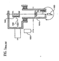
- FIG. 1 is a schematic view of a cutting apparatus known in the art.
- FIG. 2 is a perspective illustration of a cutting table incorporating the present invention.
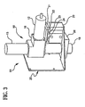
- FIG. 3 is a perspective view showing one embodiment of the invention.
- FIG. 4 is a partial view showing internals of one embodiment of the present invention.
- FIG. 5 is an exploded view showing portions of the internals of the embodiment of FIG. 4 .
- FIG. 6 is an enlarged view showing a ball bearing in a spool for converting rotary motion to linear motion.
- FIG. 7 is an enlarged view showing the ball bearing of FIG. 6 with a pressure distributor for reducing contact stress in the spool.
- FIG. 8 is an enlarged partial perspective view showing a coupling for a tangent axis drive motor.
- FIG. 9 is an enlarged partial perspective view showing a coupling for a reciprocation drive motor.
- FIG. 10 is the present invention having a blade that is reciprocated by a mass spring system that has motion provided by an electromagnetic actuator.
- FIG. 11 is a partial perspective view showing portions of the embodiment of FIG. 10 .
- FIG. 1 illustrates a cutting apparatus known in the art.
- a motor driven crank arm 1030 generates the reciprocation motion.
- At the end of the crank arm is a ball bearing whose outer race is captured between flanges of a spool.
- the spool motion is linear and is guided by linear ball bearings 1040 at each end.
- a computer controlled tangent axis drive motor 1000 is coupled to a housing tube 1010.
- the housing tube is keyed to a reciprocating knife 1020 such that it may be oriented tangent to cut a path through work material.
- One limitation of this existing apparatus is that the inertia of the housing tube is oriented along with the knife. The extra inertia may slow the angular acceleration of the knife's orientation.
- the present invention eliminates the need of a rotating housing tube and consequently increases the speed of knife orientation.
- the present invention is not limited to driving the knife through a reciprocation drive motor.
- Other means of reciprocating the knife are possible, such as , but not limited to, a mass spring system that is excited by an electromagnetic actuator.
- FIG. 2 Shown in FIG. 2 is a cutting table generally designated by the reference number 100.
- the table includes a frame 101 and a work material support surface 102 adapted to carry at least one layer of sheet-type work material 105.
- the work material includes, but is not limited to, leather or vinyl thereon.
- a beam 103 is coupled to the frame for movement back-and-forth in a first direction as indicated by the arrows labeled "X.”
- a carriage 104 is mounted to the beam 103 and is movable back-and-forth along a second direction as indicated by the arrows labeled "Y.”
- a tool head 51 is mounted to the carriage and moves in the directions "X" and "Y” in response to commands issued from a controller 106.
- FIG. 3 illustrates one embodiment of the tool head 51, which includes a main support bracket 25, a power tool generally designated 50, and a guided pneumatic cylinder designated by reference numerals 20, 21, 22, 23, and 24, which in response to commands issued by the controller 106, engages and disengages the power tool 50 with the work material 105.
- a bushing block 26 guides and supports the knife end of the power tool 50.
- FIG. 4 and 5 Illustrated in FIG. 4 and 5 are the internals of one embodiment of the power tool 50.
- a knife 1 is held in a tool holder 2.
- a rod 4 connects the tool holder 2 to a spool 5.
- a bushing 3 permits rotary and linear motion and supports the knife end of the rod 4.
- a servomotor 13 orients the heading of the knife 1 in response to commands issued from the controller.
- a crankshaft 15 has an eccentric end 8 onto which the ball bearing 6 is press fit.
- a motor 12 is attached to a second coupling 11 that drives the first bearing 6 in an orbit between the flanges of the spool 5.
- the second coupling has a head 10 to assist in connection.
- the orbit motions cause the spool 5 to reciprocate in a linear motion.
- the knife 1 reciprocates.
- the servomotor 13 and the motor 12 can be attached to a housing 16.
- the outer race of the double row ball bearing 9 fits into a round pocket in the housing 16, and is secured by an internal retaining ring.
- a tube 17 leads away from the housing 16.
- the remote end of the housing tube has external thread onto which is screwed a presser foot 19.
- the threads provide a means of adjusting the maximum cutting depth.
- a spring-loaded catch 18 prevents the presser foot from rotating during cutting operation. It is apparent that other means known by those skilled in the art can be utilized to adjust the height of the cutting knife and secure the adjustment. The above are examples and are not mentioned to limit the invention to these particular embodiments.
- FIG 6 illustrates ball bearing 6 being constrained between the flanges of the spool 5.
- a pressure distributor 7 may be attached to the outer race of the ball bearing 6. This reduces the contact stresses on the flanges of the spool 5.
- the servomotor 13 has an output shaft 28 that is attached a first coupling 14.
- the output shaft passes through a slot 27 in the first coupling 14.
- the spool 5 has a hole feature 29, a first flat 30, a second flat 31 that mate with the slot 27 of the first coupling 14.
- the spool 5 is fabricated from, but not limited to, Teflon® (tetrafluroethyene) filled acetal.
- the first coupling 14 depending on the embodiment is made from, but not limited to, stainless steel.
- the second coupling 11 has a slot, through which passes the shaft 33 of the motor 12.
- the crankshaft 15 has a hole feature 35 and a plurality of flats 36, 37, 38 and 39. These flats mate with the slot 32 of the second coupling 11 and the shaft 33.
- the crankshaft 15 is supported by a double row ball bearing 9 shown in FIG. 5 that is retained by an external retaining ring that is placed in a groove feature 34 of the crankshaft 15.
- FIG. 10 shows an embodiment of the power tool 50 where a mass-spring system is utilized and powered by an electromagnetic actuator.
- the electromagnetic actuator replaces the reciprocating drive motor.
- a servomotor 2101 orients a knife 2013 tangent to the cut path. Attached to the servomotor 2101 is an encoder 2102 or other means of angular shaft position feedback.
- Rod 2106 is slidably coupled to move relative to housing 2001.
- a first linear bearing 2008 and a second linear bearing 2009 are included to provide a means of sliding contact for rod 2106.
- a transducer 2053 provides feedback of the motion of knife 2013.
- the knife 2013 is secured to a knife holder 2012 that is coupled to rod 2106.
- a voice coil actuator that comprises of a coil 2002 and a magnetic field assembly 2003 provides excitation or actuation of the mass spring system.
- the first linear bearing 2008 is disposed in a bearing support 2010 that is attached to magnetic field assembly 2003.
- a first spring 2005 and a second spring 2006 provide elastic elements of the dynamic system.
- FIG. 11 is an enlarged partial view showing portions of the embodiment of FIG. 10 .
- the servomotor has an output shaft 2103 to which is attached a first hub 2104.
- the first hub 2104 has a slot 2115, and into the space formed by the slot 2115 the output shaft passes.
- the first hub 2104 mates with a second hub 2105, that has a first flat surface 2113, a second flat surface 2114, and a hole 2112 whose diameter is a location-clearance fit to the output shaft 2103.
- a rod 2106 is attached to the second hub 2105.
- the first hub 2104 and the second hub 2105 form a coupling that allows translation while stopping rotation of the rod 2106 relative to the output shaft 2103.
- the hubs include but are not limited to, materials that accommodate the relative sliding motion.
- the first hub 2104 may be fabricated of stainless steel, and the second hub 2105 of tetrafluroethylene filled acetal.
- the second hub 2105 may be fabricated of stainless steel, and the second hub 2105 of tetrafluroethylene filled acetal.
- a cupped spool 2004 has a cup feature 2112 that radially captures a flange feature 2107 of the rod 2106.
- a first thrust bearing 2108, a second thrust bearing 2109, a third spring 2110, and a cup washer 2111 capture the flange feature 2107 axially.
- the first thrust bearing 2108, a second thrust bearing 2109 may be fabricated from, for example, plastic suitable for bearing applications. Thrust washers of sintered bronze impregnated with oil are another example of a substitute.
- the servomotor 2101 orients the knife 2013.
Landscapes
- Life Sciences & Earth Sciences (AREA)
- Forests & Forestry (AREA)
- Engineering & Computer Science (AREA)
- Mechanical Engineering (AREA)
- Nonmetal Cutting Devices (AREA)
- Control Of Cutting Processes (AREA)
- Turning (AREA)
Claims (14)
- Appareil pour couper un matériau de travail de type feuille (105), l'appareil ayant un outil motorisé (50), l'outil motorisé comprenant : un couteau de coupe (1) disposé dans un porte-outil (2) ; caractérisé par une tige ayant une extrémité distale et une extrémité proximale, et une bobine (5) ; l'extrémité proximale étant fixée à la bobine, et l'extrémité distale étant fixée au porte-outil ; une douille (3) disposée entre le couteau et la bobine pour permettre le mouvement rotatif et linéaire du couteau ; des moyens pour donner au couteau fournir le mouvement alternatif pour couper ; et un moteur d'entraînement (13) fixé à la bobine, le moteur d'entraînement étant configuré pour orienter la direction du couteau pour qu'il soit tangentiel par rapport à une trajectoire de coupe en réponse aux commandes émises par un organe de commande (106).
- Appareil selon la revendication 1, dans lequel les moyens de mouvement alternatif sont un moteur (12).
- Appareil selon la revendication 2, dans lequel le moteur est couplé à la bobine par un vilebrequin (15).
- Appareil selon la revendication 3, dans lequel la bobine a des brides et le vilebrequin a une extrémité excentrique (8) couplée à au moins un roulement à billes (6) disposé entre les brides de la bobine pour provoquer un mouvement orbital afin de faire effectuer un mouvement alternatif au couteau.
- Appareil selon la revendication 4, dans lequel le roulement à billes comprend en outre un distributeur de pression (7) pour réduire les contraintes de contact dans les brides.
- Appareil selon la revendication 1, dans lequel les moyens de mouvement alternatif sont un système de ressort de masse actionné par un actionneur électromagnétique.
- Appareil selon la revendication 1, dans lequel le moteur d'entraînement est un servomoteur (13).
- Appareil selon la revendication 1, dans lequel le moteur d'entraînement et les moyens de mouvement alternatif sont fixés sur un boîtier ayant des moyens pour ajuster la profondeur de coupe du couteau.
- Appareil selon la revendication 8, comprenant en outre des moyens pour fixer l'ajustement de hauteur du couteau de coupe.
- Appareil selon la revendication 9, dans lequel les moyens de fixation sont un loquet à ressort (18) et les moyens d'ajustement de hauteur sont un filetage externe sur le boîtier couplé avec un pied presseur vissé.
- Appareil pour couper un matériau de travail de type feuille (105) selon la revendication 1, 2, 3 ou 6, comprenant :une surface de support (102) montée sur un châssis (101) pour porter au moins une couche de matériau de travail de type feuille sur celui-ci ;un chariot (104) couplé au châssis pour le mouvement dans différentes directions en réponse aux commandes émises par l'organe de commande ; etune tête d'outil (51) montée sur le chariot et ayant ledit outil motorisé et une tête de coupe à vérin pneumatique guidée, la tête d'outil étant mobile dans différentes directions en réponse aux commandes provenant de l'organe de commande, l'outil motorisé pouvant se mettre en prise et se dégager du matériau de travail en réponse aux commandes provenant de l'organe de commande.
- Appareil selon la revendication 11, dans lequel :la bobine est réalisée avec un matériau ayant un faible coefficient de friction ; et/oule matériau de travail est du cuir.
- Appareil selon la revendication 11, dans lequel le moteur d'entraînement est un servomoteur (13).
- Appareil selon la revendication 13, comprenant en outre un boîtier (16) ayant des moyens pour ajuster la profondeur de coupe du couteau.
Applications Claiming Priority (2)
| Application Number | Priority Date | Filing Date | Title |
|---|---|---|---|
| US11/382,242 US7798042B2 (en) | 2006-05-08 | 2006-05-08 | Reciprocated knife having an integral tangent axis orientation drive |
| PCT/US2006/018005 WO2007133196A1 (fr) | 2006-05-08 | 2006-05-09 | Outil de coupe à mouvement alternatif comprenant un organe d'entraînement d'orientation à axe tangentiel solidaire |
Publications (3)
| Publication Number | Publication Date |
|---|---|
| EP2015905A1 EP2015905A1 (fr) | 2009-01-21 |
| EP2015905A4 EP2015905A4 (fr) | 2011-03-02 |
| EP2015905B1 true EP2015905B1 (fr) | 2013-07-31 |
Family
ID=38660022
Family Applications (1)
| Application Number | Title | Priority Date | Filing Date |
|---|---|---|---|
| EP20060759453 Expired - Lifetime EP2015905B1 (fr) | 2006-05-08 | 2006-05-09 | Outil de coupe à mouvement alternatif comprenant un organe d'entraînement d'orientation à axe tangentiel solidaire |
Country Status (5)
| Country | Link |
|---|---|
| US (1) | US7798042B2 (fr) |
| EP (1) | EP2015905B1 (fr) |
| JP (1) | JP5283617B2 (fr) |
| CN (1) | CN101437656B (fr) |
| WO (1) | WO2007133196A1 (fr) |
Cited By (2)
| Publication number | Priority date | Publication date | Assignee | Title |
|---|---|---|---|---|
| DE102020105416A1 (de) | 2020-02-28 | 2021-09-02 | bullmer GmbH | Schneidkopf für eine zuschnittmaschine und verwendung eines torquemotors |
| DE102021201395A1 (de) | 2021-02-15 | 2022-08-18 | Frimo Group Gmbh | Schneidvorrichtung sowie Verfahren |
Families Citing this family (13)
| Publication number | Priority date | Publication date | Assignee | Title |
|---|---|---|---|---|
| JP5255666B2 (ja) * | 2011-03-14 | 2013-08-07 | 株式会社レザック | カッティングツールおよびカッティングツールを備えた切断装置 |
| JP2017514494A (ja) | 2014-05-06 | 2017-06-08 | ダウ アグロサイエンシィズ エルエルシー | 種子準備のためのシステムおよび使用の方法 |
| JP2017521747A (ja) | 2014-05-06 | 2017-08-03 | ダウ アグロサイエンシィズ エルエルシー | 種子を撮像および配向するためのシステムならびに使用の方法 |
| EP3139722A4 (fr) * | 2014-05-06 | 2018-01-10 | Dow Agrosciences LLC | Système pour couper et préparer des graines et procédé d'utilisation correspondant |
| DE102015007998B4 (de) * | 2015-06-24 | 2024-09-05 | Capex lnvest GmbH | Vorrichtung und Verfahren zum Durchdringen eines flächenhaften, biegeschlaffen Körpers |
| TWI566866B (zh) | 2016-07-18 | 2017-01-21 | 東友科技股份有限公司 | 切割刀具組 |
| CN107398932B (zh) * | 2017-07-27 | 2019-03-26 | 广州易能机械设备有限公司 | 一种多功能复合板切割设备 |
| DE102017124334A1 (de) * | 2017-10-18 | 2019-04-18 | Hsf Automation Gmbh | Vorrichtung zum Nutenstanzen und Stanzsystem |
| CN112405688B (zh) * | 2019-08-20 | 2025-07-15 | 宁波经纬数控股份有限公司 | 一种送纸切割机 |
| CN113070910A (zh) * | 2020-01-04 | 2021-07-06 | 郄利军 | 一种切割机机头总成 |
| JP7038871B1 (ja) | 2021-03-23 | 2022-03-18 | ローランドディー.ジー.株式会社 | シートカッター付き加工装置 |
| US11872717B2 (en) * | 2021-07-01 | 2024-01-16 | Gerber Technology Llc | Swivel knife holder assembly for a multi-ply reciprocating cutter |
| IT202200011690A1 (it) * | 2022-06-01 | 2023-12-01 | Scm Group Spa | Gruppo operatore orientabile per supporto di utensili da taglio per materiali teneri in lastre |
Family Cites Families (25)
| Publication number | Priority date | Publication date | Assignee | Title |
|---|---|---|---|---|
| US2624115A (en) * | 1951-08-20 | 1953-01-06 | Int Register Co | Portable reciprocating cutting machine |
| US3477322A (en) * | 1966-09-21 | 1969-11-11 | Gerber Scientific Instr Co | Device for cutting sheet material |
| US3747454A (en) * | 1971-06-24 | 1973-07-24 | Gerber Garment Technology Inc | Apparatus for cutting sheet material |
| US3772949A (en) * | 1972-01-17 | 1973-11-20 | Gerber Scientific Instr Co | Method and apparatus for cutting sheet material |
| US4048891A (en) * | 1976-10-26 | 1977-09-20 | Gerber Garment Technology, Inc. | Cutter mechanism for cutting sheet material |
| JPS5425350U (fr) * | 1977-07-20 | 1979-02-19 | ||
| US4653362A (en) * | 1985-05-22 | 1987-03-31 | Gerber Scientific Inc. | Cutting apparatus with heated blade for cutting thermoplastic fabrics and related method of cutting |
| ES8704786A1 (es) * | 1986-04-16 | 1987-05-01 | Investronica Sa | Mecanismo mejorado de afilado de cuchilla y guiado de la misma |
| FR2636879B1 (fr) * | 1988-09-23 | 1995-01-27 | Lectra Systemes Sa | Dispositif de coupe et de poinconnage pour matieres en feuilles |
| JPH061353Y2 (ja) * | 1988-12-27 | 1994-01-12 | 武藤工業株式会社 | 裁断ヘッドにおけるカッター昇降装置 |
| JPH0360994A (ja) * | 1989-07-28 | 1991-03-15 | Takatori Haitetsuku:Kk | シート材料を切断する方法およびその装置 |
| JPH0755468B2 (ja) * | 1989-09-20 | 1995-06-14 | 株式会社川上製作所 | 積層物の裁断装置 |
| US5090284A (en) * | 1989-12-19 | 1992-02-25 | Hitachi Seiko, Ltd | Mechanisms for driving punch pins in punching apparatus |
| US5113736A (en) * | 1990-06-26 | 1992-05-19 | Meyerle George M | Electromagnetically driven punch press with magnetically isolated removable electromagnetic thrust motor |
| US5269213A (en) * | 1992-02-25 | 1993-12-14 | International Business Machines Corporation | Punch apparatus |
| IL105743A0 (en) * | 1992-06-11 | 1993-09-22 | Dov Shilkrut | Penetrating tool system |
| US6484613B1 (en) * | 1993-07-27 | 2002-11-26 | International Business Machines Corporation | Electromagnetic bounce back braking for punch press and punch press process |
| JPH0815718B2 (ja) * | 1993-08-20 | 1996-02-21 | 株式会社島精機製作所 | 裁断刃の刃幅測定装置 |
| DK0679482T3 (da) | 1994-04-26 | 1998-05-04 | Investronica Sa | Styreindretning til kniv ophængt i en skæremaskine til skæring af materialeark |
| DE69407572T2 (de) * | 1994-04-26 | 1998-04-23 | Investronica Sa | Vorrichtung zum Führen eines Hängemessers in einer Schneidmaschine zum Schneiden von Blattmaterial |
| US5727433A (en) * | 1995-09-08 | 1998-03-17 | Gerber Garment Technology, Inc. | Method for cutting sheet material |
| DE29615396U1 (de) * | 1996-09-04 | 1998-01-08 | FEV Motorentechnik GmbH & Co. KG, 52078 Aachen | Elektromagnetischer Aktuator mit Aufschlagdämpfung |
| US6892616B2 (en) * | 2000-11-28 | 2005-05-17 | Uht Corporation | Cutting apparatus |
| EP1331068A3 (fr) * | 2002-01-25 | 2003-09-10 | Heidel GmbH & Co. KG, Werkzeug- u. Maschinenfabrikation | Outil de coupe comprenant une tête de coupe ayant des moyens d'entraínement |
| US7011007B2 (en) * | 2002-07-26 | 2006-03-14 | Gerber Technology, Inc. | Apparatus for cutting and creating notches and apertures in sheet-type work material |
-
2006
- 2006-05-08 US US11/382,242 patent/US7798042B2/en active Active
- 2006-05-09 CN CN2006800545011A patent/CN101437656B/zh not_active Expired - Lifetime
- 2006-05-09 JP JP2009509524A patent/JP5283617B2/ja not_active Expired - Lifetime
- 2006-05-09 EP EP20060759453 patent/EP2015905B1/fr not_active Expired - Lifetime
- 2006-05-09 WO PCT/US2006/018005 patent/WO2007133196A1/fr not_active Ceased
Cited By (3)
| Publication number | Priority date | Publication date | Assignee | Title |
|---|---|---|---|---|
| DE102020105416A1 (de) | 2020-02-28 | 2021-09-02 | bullmer GmbH | Schneidkopf für eine zuschnittmaschine und verwendung eines torquemotors |
| DE102020105416B4 (de) | 2020-02-28 | 2022-06-15 | bullmer GmbH | Schneidkopf für eine zuschnittmaschine |
| DE102021201395A1 (de) | 2021-02-15 | 2022-08-18 | Frimo Group Gmbh | Schneidvorrichtung sowie Verfahren |
Also Published As
| Publication number | Publication date |
|---|---|
| JP2009536584A (ja) | 2009-10-15 |
| CN101437656B (zh) | 2013-02-27 |
| JP5283617B2 (ja) | 2013-09-04 |
| US20070256530A1 (en) | 2007-11-08 |
| WO2007133196A1 (fr) | 2007-11-22 |
| EP2015905A1 (fr) | 2009-01-21 |
| EP2015905A4 (fr) | 2011-03-02 |
| CN101437656A (zh) | 2009-05-20 |
| US7798042B2 (en) | 2010-09-21 |
Similar Documents
| Publication | Publication Date | Title |
|---|---|---|
| US7798042B2 (en) | Reciprocated knife having an integral tangent axis orientation drive | |
| JPH0433595B2 (fr) | ||
| CA1119848A (fr) | Presse a percussion a manchon porte-piston | |
| US4667553A (en) | Notching tool with presser foot | |
| JPH05237710A (ja) | 工作機械およびその作動方法 | |
| CN105904514A (zh) | 一种用于柔性材料切割的冲切机头及其控制方法 | |
| US7097399B2 (en) | Cutting machine for gear shaping or the like | |
| US20090229439A1 (en) | Processing machine with reciprocation device | |
| US5829372A (en) | Mechanical tufting head | |
| US4879935A (en) | Reciprocating knife cutter with flexible drive portion | |
| JP2012179671A (ja) | 加工装置 | |
| CN1013483B (zh) | 用线材卷制弹簧的装置 | |
| CA1043212A (fr) | Avance du specimen sur un microtome | |
| JPS62501984A (ja) | リニア−ドライブ装置 | |
| JP2981138B2 (ja) | 直線運動を回転運動に変換する装置および同装置を用いたプレス機械用回転工具装置 | |
| CN216265362U (zh) | 数字化浮动磨抛主轴 | |
| CN214882203U (zh) | 一种带有自动换梭装置的缝纫机 | |
| JPH047371Y2 (fr) | ||
| US7418783B2 (en) | Clamping mechanism for tool holder | |
| JP3584052B2 (ja) | 切断機のストローク調整機構 | |
| CN204076388U (zh) | 一种超声波切带机 | |
| CN218083107U (zh) | 一种高频率长寿命气动真皮冲孔机头 | |
| JP7461653B2 (ja) | プレス機械 | |
| JP4206214B2 (ja) | 食肉スライサー | |
| JP4153749B2 (ja) | プレス機械 |
Legal Events
| Date | Code | Title | Description |
|---|---|---|---|
| PUAI | Public reference made under article 153(3) epc to a published international application that has entered the european phase |
Free format text: ORIGINAL CODE: 0009012 |
|
| 17P | Request for examination filed |
Effective date: 20081127 |
|
| AK | Designated contracting states |
Kind code of ref document: A1 Designated state(s): AT BE BG CH CY CZ DE DK EE ES FI FR GB GR HU IE IS IT LI LT LU LV MC NL PL PT RO SE SI SK TR |
|
| AX | Request for extension of the european patent |
Extension state: AL BA HR MK YU |
|
| DAX | Request for extension of the european patent (deleted) | ||
| RBV | Designated contracting states (corrected) |
Designated state(s): DE FR GB |
|
| A4 | Supplementary search report drawn up and despatched |
Effective date: 20110202 |
|
| RIC1 | Information provided on ipc code assigned before grant |
Ipc: B26D 5/06 20060101ALI20110127BHEP Ipc: B26D 5/08 20060101AFI20080121BHEP Ipc: B26D 5/16 20060101ALI20110127BHEP |
|
| 17Q | First examination report despatched |
Effective date: 20110217 |
|
| GRAP | Despatch of communication of intention to grant a patent |
Free format text: ORIGINAL CODE: EPIDOSNIGR1 |
|
| RIC1 | Information provided on ipc code assigned before grant |
Ipc: B26D 5/16 20060101ALI20130125BHEP Ipc: B26D 5/08 20060101AFI20130125BHEP Ipc: B26F 1/38 20060101ALI20130125BHEP Ipc: B26D 5/06 20060101ALI20130125BHEP |
|
| GRAS | Grant fee paid |
Free format text: ORIGINAL CODE: EPIDOSNIGR3 |
|
| GRAA | (expected) grant |
Free format text: ORIGINAL CODE: 0009210 |
|
| AK | Designated contracting states |
Kind code of ref document: B1 Designated state(s): DE FR GB |
|
| REG | Reference to a national code |
Ref country code: GB Ref legal event code: FG4D |
|
| REG | Reference to a national code |
Ref country code: DE Ref legal event code: R096 Ref document number: 602006037640 Country of ref document: DE Effective date: 20130926 |
|
| PLBI | Opposition filed |
Free format text: ORIGINAL CODE: 0009260 |
|
| PLAX | Notice of opposition and request to file observation + time limit sent |
Free format text: ORIGINAL CODE: EPIDOSNOBS2 |
|
| 26 | Opposition filed |
Opponent name: LECTRA Effective date: 20140423 |
|
| REG | Reference to a national code |
Ref country code: DE Ref legal event code: R026 Ref document number: 602006037640 Country of ref document: DE Effective date: 20140423 |
|
| PLAF | Information modified related to communication of a notice of opposition and request to file observations + time limit |
Free format text: ORIGINAL CODE: EPIDOSCOBS2 |
|
| PLBB | Reply of patent proprietor to notice(s) of opposition received |
Free format text: ORIGINAL CODE: EPIDOSNOBS3 |
|
| REG | Reference to a national code |
Ref country code: FR Ref legal event code: PLFP Year of fee payment: 11 |
|
| PLCK | Communication despatched that opposition was rejected |
Free format text: ORIGINAL CODE: EPIDOSNREJ1 |
|
| APAH | Appeal reference modified |
Free format text: ORIGINAL CODE: EPIDOSCREFNO |
|
| APBM | Appeal reference recorded |
Free format text: ORIGINAL CODE: EPIDOSNREFNO |
|
| APBP | Date of receipt of notice of appeal recorded |
Free format text: ORIGINAL CODE: EPIDOSNNOA2O |
|
| REG | Reference to a national code |
Ref country code: FR Ref legal event code: PLFP Year of fee payment: 12 |
|
| REG | Reference to a national code |
Ref country code: DE Ref legal event code: R100 Ref document number: 602006037640 Country of ref document: DE |
|
| PLAB | Opposition data, opponent's data or that of the opponent's representative modified |
Free format text: ORIGINAL CODE: 0009299OPPO |
|
| APBU | Appeal procedure closed |
Free format text: ORIGINAL CODE: EPIDOSNNOA9O |
|
| PLBN | Opposition rejected |
Free format text: ORIGINAL CODE: 0009273 |
|
| STAA | Information on the status of an ep patent application or granted ep patent |
Free format text: STATUS: OPPOSITION REJECTED |
|
| R26 | Opposition filed (corrected) |
Opponent name: LECTRA Effective date: 20140423 |
|
| 27O | Opposition rejected |
Effective date: 20170622 |
|
| REG | Reference to a national code |
Ref country code: FR Ref legal event code: PLFP Year of fee payment: 13 |
|
| P01 | Opt-out of the competence of the unified patent court (upc) registered |
Effective date: 20230525 |
|
| PGFP | Annual fee paid to national office [announced via postgrant information from national office to epo] |
Ref country code: DE Payment date: 20250423 Year of fee payment: 20 |
|
| PGFP | Annual fee paid to national office [announced via postgrant information from national office to epo] |
Ref country code: GB Payment date: 20250423 Year of fee payment: 20 |
|
| PGFP | Annual fee paid to national office [announced via postgrant information from national office to epo] |
Ref country code: FR Payment date: 20250423 Year of fee payment: 20 |