EP2015926B1 - Tablettiermaschine - Google Patents
Tablettiermaschine Download PDFInfo
- Publication number
- EP2015926B1 EP2015926B1 EP07728864.5A EP07728864A EP2015926B1 EP 2015926 B1 EP2015926 B1 EP 2015926B1 EP 07728864 A EP07728864 A EP 07728864A EP 2015926 B1 EP2015926 B1 EP 2015926B1
- Authority
- EP
- European Patent Office
- Prior art keywords
- tableting machine
- filling
- machine according
- die table
- feed shoe
- Prior art date
- Legal status (The legal status is an assumption and is not a legal conclusion. Google has not performed a legal analysis and makes no representation as to the accuracy of the status listed.)
- Not-in-force
Links
Images


Classifications
-
- B—PERFORMING OPERATIONS; TRANSPORTING
- B30—PRESSES
- B30B—PRESSES IN GENERAL
- B30B15/00—Details of, or accessories for, presses; Auxiliary measures in connection with pressing
- B30B15/30—Feeding material to presses
- B30B15/302—Feeding material in particulate or plastic state to moulding presses
- B30B15/304—Feeding material in particulate or plastic state to moulding presses by using feed frames or shoes with relative movement with regard to the mould or moulds
-
- B—PERFORMING OPERATIONS; TRANSPORTING
- B23—MACHINE TOOLS; METAL-WORKING NOT OTHERWISE PROVIDED FOR
- B23Q—DETAILS, COMPONENTS, OR ACCESSORIES FOR MACHINE TOOLS, e.g. ARRANGEMENTS FOR COPYING OR CONTROLLING; MACHINE TOOLS IN GENERAL CHARACTERISED BY THE CONSTRUCTION OF PARTICULAR DETAILS OR COMPONENTS; COMBINATIONS OR ASSOCIATIONS OF METAL-WORKING MACHINES, NOT DIRECTED TO A PARTICULAR RESULT
- B23Q7/00—Arrangements for handling work specially combined with or arranged in, or specially adapted for use in connection with, machine tools, e.g. for conveying, loading, positioning, discharging, sorting
-
- B—PERFORMING OPERATIONS; TRANSPORTING
- B30—PRESSES
- B30B—PRESSES IN GENERAL
- B30B11/00—Presses specially adapted for forming shaped articles from material in particulate or plastic state, e.g. briquetting presses, tabletting presses
- B30B11/02—Presses specially adapted for forming shaped articles from material in particulate or plastic state, e.g. briquetting presses, tabletting presses using a ram exerting pressure on the material in a moulding space
- B30B11/08—Presses specially adapted for forming shaped articles from material in particulate or plastic state, e.g. briquetting presses, tabletting presses using a ram exerting pressure on the material in a moulding space co-operating with moulds carried by a turntable
-
- B—PERFORMING OPERATIONS; TRANSPORTING
- B30—PRESSES
- B30B—PRESSES IN GENERAL
- B30B15/00—Details of, or accessories for, presses; Auxiliary measures in connection with pressing
- B30B15/06—Platens or press rams
-
- B—PERFORMING OPERATIONS; TRANSPORTING
- B30—PRESSES
- B30B—PRESSES IN GENERAL
- B30B15/00—Details of, or accessories for, presses; Auxiliary measures in connection with pressing
- B30B15/30—Feeding material to presses
Definitions
- the invention relates to a tableting machine with a die table, which comprises at least one die, and a filling device for filling a mass to be pressed into the dies.
- Tabletting machines of the generic type are known.
- a rotor bearing the die table is set in rotation by a drive machine.
- the matrices are filled with the mass to be pressed and depending on the angular position of the rotor guided over guide curves lower punch and upper punch are axially displaced to the matrices.
- the lower and upper punches are guided past at least one pressing station, usually at a pre-pressing station and a main pressing station.
- the upper and lower punches of stationary pressure rollers are guided substantially tangentially, so that a pressing force can be applied to the introduced in the matrices molding compound.
- Such rotary tabletting machines are used inter alia in the production of pharmaceutical, chemical and technical compacts. Especially in these areas, but also in other applications, it comes to a lossless and thus pollution-free production on. Furthermore, the simplest possible cleaning of rotary tablet tableting machines is essential.
- a press for pressing powdery material according to the preamble of claim 1 in which a sealing device is arranged between a filling shoe and a die table.
- the sealing device is acted upon by the force of a spring element in the direction of the die table.
- the sealing device is in this case arranged at a distance to a contour of a filling opening of the filling shoe, so that it comes to the formation of cavities between the filling shoe and the die table, in which accumulates material to be pressed.
- the invention has for its object to provide a tableting machine of the generic type, which is characterized by a simple structure and an effective seal between filling device for mass to be pressed and die table provides.
- a sealing device between filling shoe and die table comprises at least one element directly forming the filling opening, which is acted upon by a force acting in the direction of the die table, which is fastened by means of a spring joint to a base body of the filling shoe and which is a profile ring is in very effectively sealing the gap between filling shoe and die table possible.
- the element which is preferably prestressed by a spring force, is located on the die table with a low contact pressure, so that a discharge of material to be pressed and an introduction of foreign substances is not possible here.
- the serving as a spring element and mounting element profile ring form the contour of the filling opening forming element and the filling shoe to the shape of the profile ring complementary receptacles.
- These recordings are preferably designed as edge-open, circumferential grooves.
- the spring element also serves as a fastening element of the contour of the filling opening forming element, so that can be dispensed with further additional fastening means, such as screws and the like.
- the profile ring receiving contours of the filling shoe or of the element are formed so that an assembly of only one side, here preferably of the die table side facing, the filling shoe is possible. Thus, incorrect assembly can be avoided. On the other hand, such pushing out or the like of the element during the intended use in the operation of the tabletting machine can be prevented.
- both the contour of the filling opening forming Element as well as the spring element from the materials to be performed with the tabletting machine manufacturing processes adapted materials, especially temperature-resistant materials, neutral materials, against the powder to be pressed and the like.
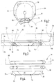
- FIG. 1 shows a schematic partial view of the image of a die table 12 of a generally designated 10 rotary tableting machine.
- the die table 12 has over its circumference a plurality of spaced dies 14.
- Each die 14 is associated with a lower punch 16 and an upper punch 18, which are guided over here indicated guide curves 20 and 22 respectively.
- Die table 12 and lower punch 16 and upper punch 18 rotate synchronously about the axis of rotation of the die table 12.
- the die table 12 is rotatable by an electric drive machine 24 only indicated here.
- a filling device 26 which includes a so-called filling shoe 28, a here merely indicated molding compound 30.
- the molding compound 30 is filled over the entire height of the dies 14.
- the filling level can be defined, for example, by the height of the lower punches 16 at a stripping station, not shown.
- the filling shoe 28 communicates with a reservoir 32, from which the molding compound 30 is fed to the filling shoe 28.
- the filling shoe 28 has a - in FIG. 1 unrecognizable - Fill opening through which the mass 30 enters the matrices 14.
- Within the filling shoe 28 usually rotating metering wheels, baffles, barrages or the like are arranged, which ensure a uniform supply of molding compound 30.
- the filling shoe 28 is arranged parallel to a surface 34 of the die table 12. Between filling shoe 28 and die table 12, a gap 36 is formed so that upon rotation of the die table 12, the filling shoe 28 does not come into direct abutting contact with the die table 12.
- element 38 is provided in the area of the filling opening.
- the element 38 forms the contour of the filling opening and is acted upon by a spring force acting in the direction of the die table 12, so that the element 38 bears against the surface 34 of the die table 12.
- the spring force with which the element 38 is acted upon and urged in the direction of the die table 12 is dimensioned so that only a slight contact is given here.
- the installation of the element 38 on the die table 12 serves to seal the gap 36 in the region of the filling opening.
- the lower punches 16 and the upper punches 18 dive into the dies 14 and press the molding compound 30 to the desired tablet or the like.
- the lower punches 16 and the upper punches 18 are guided past at least one pressing station 40, which comprises fixedly arranged pressure rollers 42.
- the pressure rollers 42 are each rotatably mounted about a rotation axis 44. The distance of the pressure rollers 42 to each other is defined and ultimately determines the height of the tablet to be pressed.
- FIG. 2 shows a schematic bottom view of the filling shoe 28. That is, in FIG. 2 is a plan view of the filling shoe 28 from the direction of the die table 12 is shown.
- the filling shoe 28 comprises a base body 50 into which a recess 52 is made.
- the recess 52 is open at the side facing away from the die table 12 and there closed by a plate not shown in detail.
- the recess 52 is formed substantially circular. Within this recess 52, the metering wheel, not shown rotates.
- the filling opening 54 is formed at the bottom of the recess 52.
- the filling opening 54 is formed in a circular arc, wherein an imaginary arc line of the filling opening 54 with an in FIG. 2 indicated orbit 56 of the dies 14 coincides.
- a contour 58 of the filling opening 54 is determined by the element 38, which is arranged via a designed as a profile ring 60 spring element within the main body 50 of the filling shoe 28.
- the element 38 has one or more central webs 62 which connects the two longitudinal sides of the element 38 with each other.
- the central web 62 is in this case opposite the bearing surface 64 pointing in the direction of the die table 12 (FIG. FIG. 3 ) so that it does not come into abutting contact with the die table 12.
- the central web 62 serves to fix the Element 38 in a receiving groove 66 of the filling shoe 28. According to a further embodiment, not shown, the central webs can come into abutting contact with the die table 12.
- FIG. 3 shows a sectional view through the filling opening 54.
- the same parts as in the preceding figures are provided with the same reference numerals and not explained again.
- the main body 50 forms a receiving groove 66 for the profile ring 60.
- the receiving groove 66 proceeds from a first section 68-which runs essentially perpendicular to the underside 70 of the main body 50-into a circular section 72 and from there into a third section 74, which runs parallel to the section 68.
- the sections 68 and 74 of the receiving groove 66 are not in one plane.
- the section 74 is displaced further in the direction of the filling opening 54, so that there is virtually the formation of a step between the underside 70 and the bottom 76 of the recess 52.
- the element 38 also forms a guide groove 78 for the profile ring 60.
- This guide groove 78 is formed on the peripheral edge of the element 38.
- the element 38 itself has an extension which, when the element 38 is inserted into the filling shoe 28, is smaller than the distance of the opposite sections 68 of the receiving groove 66 and greater than the opposite distance between the sections 74 of the receiving groove 66 the element 38 only from one side, namely from the bottom 70 ago, can be inserted into the main body 50 of the filling shoe 28.
- the element 38 is flush with the portion 74 of the receiving groove 66 from. This ensures that when mounting the filling shoe 28 on the rotary tablet-making machine 10, the element 38 can be arranged with a low contact pressure on the bearing surfaces 64 on the surface 34 of the die table 12. The element 38 is in this case urged in the direction of the filling shoe 28. About the profile ring 60, which acts as a spring element, a corresponding opposing force is exerted on the element 38 so that it is biased in the direction of the die table 12.
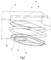
- FIG. 4 shows in an exploded view again in a sectional view of the element 38, the profile ring 60 and the main body 50 of the filling shoe 28.
- an inner surface 82 of the element 38 is arranged funnel-shaped. As a result, the filling of the material to be pressed in the matrices 14 is supported.
- the contour of the filling opening 54 is determined by the element 38.
- the contact surfaces 64 adjoin directly to the filling opening 54, so that the sealing of the gap 36 (FIG. FIG. 1 ) also takes place directly on the filling opening 54.
- FIG. 5 shown exploded perspective view again the element 38, the profile ring 60 and the main body 50 of the filling shoe 28 clearly.
- the Assembly of the element 38 is effected by mechanical engagement in the base body 50, wherein here via the profile ring 60 is a positive connection. Due to the elasticity of the profile ring 60, a holding force is exerted on the element 38. At the same time, the profile ring 60 assumes the effect of a spring element when the filling shoe 28 is mounted.
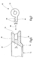
- FIGS. 6 and 7 is a possible corresponding embodiment of the profile ring 60 (FIG. FIG. 7 ) on the one hand and the guide groove 78 of the element 38 (FIG. FIG. 6 ) on the other hand.
- FIG. 6 shows a sectional view through an edge region of the element 38 and FIG. 7 a sectional view through a profile ring 60.
- the guide groove 78 comprises an extending into the main body 38 annular groove 84.
- the profile ring 60 in turn forms an annular bead 86, which - as the indicated arrow 88 illustrates - in the annular groove 84 can be introduced.
- the annular bead 86 comprises unidirectional nose-shaped projections 90 spaced apart from one another. A height h 1 of the nose-shaped projections 90 is slightly larger than a height h 2 of the annular groove 84.
- the profile ring 60 also has an annular channel 92, which leads to a better, adjustable by dimensioning of the annular channel 62 compressibility and thus influencing the spring tension. This will in addition to the sealing effect also the automatic adjustability to compensate for wear possible.
- FIG. 8 is a sectional view of a profile ring 60 on the main body 50 of a Drschuhs arranged element 38 illustrated.
- the self-adjusting, resilient mounting of the element 38 via the profile ring 60 on the main body 50 becomes clear.
- the profile ring 60 which revolves completely around the element 38, holds the element 80 in a defined, spring-elastic position in the main body 50.
- the profile ring 60 may differ in cross section from a circular shape.
- oval, trapezoidal or other suitable cross-sections are conceivable.
- a correspondingly adapted contour of the receiving groove 66 and the guide groove 78 is required.
Landscapes
- Engineering & Computer Science (AREA)
- Mechanical Engineering (AREA)
- Processing And Handling Of Plastics And Other Materials For Molding In General (AREA)
- Medical Preparation Storing Or Oral Administration Devices (AREA)
- Glanulating (AREA)
Description
- Die Erfindung betrifft eine Tablettiermaschine mit einem Matrizentisch, der wenigstens eine Matrize umfasst, und einer Einfülleinrichtung zum Einfüllen einer zu pressenden Masse in die Matrizen.
- Tablettiermaschinen der gattungsgemäßen Art sind bekannt. Hierbei wird beispielsweise bei Rundläufer-Tablettiermaschinen ein den Matrizentisch tragender Rotor durch eine Antriebsmaschine in Rotation versetzt. Über wenigstens einen so genannten Füllschuh werden die Matrizen mit der zu pressenden Masse gefüllt und je nach Winkelstellung des Rotors werden über Führungskurven geführte Unterstempel und Oberstempel axial zu den Matrizen verlagert. Die Unter- und Oberstempel werden an wenigstens einer Pressstation, in der Regel an einer Vorpressstation und einer Hauptpressstation, vorbeigeführt. Dort werden die Ober- und Unterstempel an stationär angeordneten Druckrollen im Wesentlichen tangential vorbeigeführt, so dass auf die in den Matrizen eingebrachte Pressmasse eine Presskraft aufbringbar ist.
- Derartige Rundläufer-Tablettiermaschinen werden unter anderem bei der Herstellung von pharmazeutischen, chemischen und technischen Presslingen eingesetzt. Insbesondere in diesen Bereichen, jedoch auch bei anderen Anwendungsgebieten, kommt es auf eine verlustfreie und damit verschmutzungsfreie Fertigung an. Ferner ist eine möglichst einfache Reinigung der Rundläufer-Tablettiermaschinen unablässig.
- Insbesondere beim Einbringen der zu pressenden Masse über den Füllschuh in die Matrizen ist eine möglichst dichte Anordnung erforderlich, um einerseits den Austrag von Material zu behindern und andererseits das Eindringen von Fremdstoffen in das zu pressende Material zu verhindern. Bekannt ist, zwischen Füllschuh und Matrizentisch Dichtstreifen vorzusehen, die üblicherweise an der Unterseite des Füllschuhs beabstandet zu der wenigstens einen Füllöffnung angeordnet sind.
- Diese Dichtstreifen schleifen quasi auf der Oberfläche des Matrizentisches während dessen Rotation. Zwischen Füllöffnung und Dichtstreifen können Spalten, Hohlräume, Toträume, Taschen oder dergleichen existieren, die sich während des bestimmungsgemäßen Gebrauchs mit dem zu pressenden Material füllen und zu zusätzlichen Abdichtproblemen führen.
- Aus
US 3,577,842 ist eine Presse zum Pressen von pulverförmigen Material gemäß dem Oberbegriff des Anspruchs 1 bekannt, bei der zwischen einem Füllschuh und einem Matrizentisch eine Dichteinrichtung angeordnet ist. Die Dichteinrichtung ist durch die Kraft eines Federelementes in Richtung des Matrizentisches beaufschlagt. Die Dichteinrichtung ist hierbei beabstandet zu einer Kontur einer Füllöffnung des Füllschuhs angeordnet, so dass es zur Ausbildung von Hohlräumen zwischen dem Füllschuh und dem Matrizentisch kommt, in denen sich zu verpressenden Material ansammelt. - Der Erfindung liegt die Aufgabe zugrunde, eine Tablettiermaschine der gattungsgemäßen Art zu schaffen, die sich durch einen einfachen Aufbau auszeichnet und eine effektive Dichtung zwischen Einfülleinrichtung für zu pressende Masse und Matrizentisch bietet.
- Diese Aufgabe wird erfindungsgemäß durch eine Tablettiermaschine mit den im Anspruch 1 genannten Merkmalen gelöst. Dadurch, dass eine Dichteinrichtung zwischen Füllschuh und Matrizentisch wenigstens ein die Füllöffnung direkt ausbildendes Element umfasst, welches mit einer in Richtung des Matrizentisches wirkenden Kraft beaufschlagt ist, das mittels eines Federgelenkes an einem Grundkörper des Füllschuhs befestigt ist und das ein Profilring ist, ist in sehr effektiver Weise eine Abdichtung des Spaltes zwischen Füllschuh und Matrizentisch möglich. Das vorzugsweise durch eine Federkraft vorgespannte Element liegt mit geringem Anpressdruck quasi auf dem Matrizentisch auf, so dass hier ein Austrag von zu verpressendem Material und ein Eintrag von Fremdstoffen nicht möglich ist. Ferner wird durch die direkte Ausbildung der Füllöffnung durch die Dichteinrichtung erreicht, dass irgendwelche Hohlräume, Toträume, Taschen oder dergleichen - in denen sich zu verpressendes Material ansammeln könnte - nicht vorhanden sind.
- Erfindungsgemäß ist ferner vorgesehen, dass zur Aufnahme des als Federelement und Montageelement dienenden Profil-Ringes das die Kontur der Füllöffnung ausbildende Element und der Füllschuh zur Form des Profil-Ringes komplementäre Aufnahmen bilden. Diese Aufnahmen sind vorzugsweise als randoffene, umlaufende Nuten ausgebildet. Hierdurch wird in einfacher Weise eine werkzeuglose, selbstjustierende Montage des die Kontur der Füllöffnung ausbildenden Elementes möglich. Ferner ist durch die Lage und Ausbildung der Aufnahmen sowie des Profil-Ringes das Rückstellverhalten des Elementes einstellbar. Definierte Federkräfte und somit Anlagedrücke des Elementes an dem Matrizentisch sind somit erzielbar. Hierdurch ergibt sich außerdem eine automatische Nachstellung des Elementes, um beispielsweise eine verschleißbedingte Veränderung der Oberfläche des Matrizentisches oder des Dichtelementes auszugleichen.
- Es wird erreicht, dass in einfacher Weise eine definierte Position des Elementes erzielt werden kann, so dass neben der korrekten Ausbildung der Füllöffnung eine definierte Positionierung des Elementes möglich ist. Hierdurch wird sichergestellt, dass die gewünschten Dichteigenschaften durch das Element optimal eingehalten werden. Das Federelement dient gleichzeitig als Befestigungselement des die Kontur der Füllöffnung ausbildenden Elementes, so dass auf weitere zusätzliche Befestigungsmittel, beispielsweise Schrauben und dergleichen, verzichtet werden kann.
- In weiterer bevorzugter Ausgestaltung der Erfindung ist vorgesehen, dass die den Profil-Ring aufnehmenden Konturen des Füllschuhs beziehungsweise des Elementes so ausgebildet sind, dass eine Montage nur von einer Seite, hier vorzugsweise von der dem Matrizentisch zugewandten Seite, des Füllschuhs möglich ist. Somit werden Fehlmontagen vermieden. Andererseits kann so ein Herausdrücken oder dergleichen des Elementes während des bestimmungsgemäßen Einsatzes beim Betrieb der Tablettiermaschine verhindert werden.
- Darüber hinaus ist in bevorzugter Ausgestaltung der Erfindung vorgesehen, dass sowohl das die Kontur der Füllöffnung ausbildende Element als auch das Federelement aus den mit der Tablettiermaschine durchzuführenden Fertigungsprozessen angepassten Materialien, insbesondere temperaturbeständigen Materialien, neutralen Materialien, gegen das zu verpressende Pulver und dergleichen bestehen.
- Weitere bevorzugte Ausgestaltungen der Erfindung ergeben sich aus den übrigen, in den Unteransprüchen genannten Merkmalen.
- Die Erfindung wird nachfolgend in einem Ausführungsbeispiel anhand der zugehörigen Zeichnungen näher erläutert. Es zeigen:
- Figur 1
- eine teilweise schematische Darstellung einer Rundläufer-Tablettiermaschine;
- Figur 2
- eine schematische Draufsicht auf einen Füllschuh;
- Figur 3
- eine Schnittdarstellung durch den Füllschuh;
- Figur 4
- eine Schnittdarstellung durch eine Explosionsdarstellung des Füllschuhs;
- Figur 5
- eine teilweise Explosionsdarstellung des Füllschuhs;
- Figur 6
- eine Schnittdarstellung durch den Randbereich eines Einsetzelementes des Füllschuhs;
- Figur 7
- eine Schnittdarstellung durch einen Profil-Ring und
- Figur 8
- eine Schnittdarstellung durch einen Füllschuh mit montierten Dichtelementen.
- Rundläufer-Tablettiermaschinen der hier angesprochenen Art sind allgemein bekannt, so dass im Rahmen der vorliegenden Beschreibung auf den grundlegenden Aufbau und die grundlegenden Funktionen nicht näher eingegangen wird.
-
Figur 1 zeigt in einer schematisierten Teilansicht die Abbildung eines Matrizentisches 12 einer insgesamt mit 10 bezeichneten Rundläufer-Tablettiermaschine. Der Matrizentisch 12 besitzt über seinen Umfang eine Vielzahl beabstandeter Matrizen 14. Jeder Matrize 14 ist ein Unterstempel 16 und ein Oberstempel 18 zugeordnet, die über hier angedeutete Führungskurven 20 beziehungsweise 22 geführt sind. Matrizentisch 12 und Unterstempel 16 sowie Oberstempel 18 rotieren hierbei synchron um die Drehachse des Matrizentisches 12. Der Matrizentisch 12 ist durch eine hier nur angedeutete elektrische Antriebsmaschine 24 rotierbar. - In die Matrizen 14 wird über eine Einfülleinrichtung 26, die einen so genannten Füllschuh 28 umfasst, eine hier lediglich angedeutete Pressmasse 30 eingefüllt. Im Normalbetrieb der Rundläufer-Tablettiermaschine 10 wird die Pressmasse 30 über die gesamte Höhe der Matrizen 14 eingefüllt. Die Füllhöhe kann beispielsweise durch Höhenlage der Unterstempel 16 an einer nicht dargestellten Abstreifstation definiert werden.
- Der Füllschuh 28 steht mit einem Vorratsbehälter 32 in Verbindung, von dem die Pressmasse 30 dem Füllschuh 28 zugeführt wird. Der Füllschuh 28 besitzt eine - in
Figur 1 nicht erkennbare - Füllöffnung, über die die Masse 30 in die Matrizen 14 gelangt. Innerhalb des Füllschuhs 28 sind üblicherweise noch rotierende Dosierräder, Schikanen, Staustufen oder dergleichen angeordnet, die eine gleichmäßige Zuführung von Pressmasse 30 gewährleisten. - Der Füllschuh 28 ist parallel zu einer Oberfläche 34 des Matrizentisches 12 angeordnet. Zwischen Füllschuh 28 und Matrizentisch 12 ist ein Spalt 36 ausgebildet, so dass bei Rotation des Matrizentisches 12 der Füllschuh 28 nicht in direkten Anlagekontakt mit dem Matrizentisch 12 kommt. Im Bereich der Füllöffnung ist ein in
Figur 1 nur angedeutetes, anhand der nachfolgenden Figuren noch näher erläutertes Element 38 vorgesehen. Das Element 38 bildet die Kontur der Füllöffnung aus und ist mit einer in Richtung des Matrizentisches 12 wirkenden Federkraft beaufschlagt, so dass das Element 38 an der Oberfläche 34 des Matrizentisches 12 anliegt. Die Federkraft, mit der das Element 38 beaufschlagt und in Richtung des Matrizentisches 12 gedrängt ist, ist so bemessen, dass hier nur eine leichte Anlage gegeben ist. Die Anlage des Elementes 38 am Matrizentisch 12 dient der Abdichtung des Spaltes 36 im Bereich der Füllöffnung. - Entsprechend dem Verlauf der Führungskurven 20 und 22 tauchen die Unterstempel 16 und die Oberstempel 18 in die Matrizen 14 ein und verpressen die Pressmasse 30 zu der gewünschten Tablette oder dergleichen. Hierzu werden die Unterstempel 16 und die Oberstempel 18 an wenigstens einer Pressstation 40 vorbeigeführt, die ortsfest angeordnete Druckrollen 42 umfasst. Die Druckrollen 42 sind jeweils um eine Drehachse 44 drehbar gelagert. Der Abstand der Druckrollen 42 zueinander ist definiert und bestimmt letztendlich die Höhe der zu pressenden Tablette. Ein Antrieb der Druckrollen 42 in Pfeilrichtung 46 - die obere Druckrolle 42 entgegen dem Uhrzeigersinn, die untere Druckrolle 42 in Uhrzeigersinn - erfolgt durch Vorbeiführen der Unterstempel 16 beziehungsweise Oberstempel 18 entsprechend der Bewegungsrichtung 48 des Matrizentisches 12.
-
Figur 2 zeigt eine schematische Unteransicht des Füllschuhs 28. Das heißt, inFigur 2 ist eine Draufsicht auf den Füllschuh 28 aus Richtung des Matrizentisches 12 gezeigt. Der Füllschuh 28 umfasst einen Grundkörper 50, in den eine Vertiefung 52 eingebracht ist. Die Vertiefung 52 ist an der dem Matrizentisch 12 abgewandten Seite offen und dort durch eine im Einzelnen nicht dargestellte Platte verschließbar. Die Vertiefung 52 ist im Wesentlichen kreisrund ausgebildet. Innerhalb dieser Vertiefung 52 rotiert das nicht dargestellte Dosierrad. Am Grund der Vertiefung 52 ist die Füllöffnung 54 ausgebildet. Die Füllöffnung 54 ist kreisbogenförmig ausgebildet, wobei eine gedachte Bogenlinie der Füllöffnung 54 mit einer inFigur 2 angedeuteten Umlaufbahn 56 der Matrizen 14 zusammenfällt. Eine Kontur 58 der Füllöffnung 54 wird durch das Element 38 bestimmt, das über ein als Profil-Ring 60 ausgebildetes Federelement innerhalb des Grundkörpers 50 des Füllschuhs 28 angeordnet ist. Das Element 38 besitzt einen oder mehrere Mittelstege 62, der beziehungsweise die die beiden Längsseiten des Elementes 38 miteinander verbindet. Der Mittelsteg 62 ist hierbei gegenüber der in Richtung des Matrizentisches 12 weisenden Anlagefläche 64 (Figur 3 ) zurückgesetzt, so dass dieser nicht in Anlagekontakt mit dem Matrizentisch 12 kommt. Der Mittelsteg 62 dient der Fixierung des Elementes 38 in einer Aufnahmenut 66 des Füllschuhs 28. Nach einer weiteren, nicht dargestellten Ausführungsvariante können die Mittelstege auch in Anlagekontakt mit dem Matrizentisch 12 kommen. -
Figur 3 zeigt eine Schnittdarstellung durch die Füllöffnung 54. Gleiche Teile wie in den vorhergehenden Figuren sind mit gleichen Bezugszeichen versehen und nicht nochmals erläutert. - Anhand der Darstellung in
Figur 3 wird deutlich, dass der Grundkörper 50 eine Aufnahmenut 66 für den Profil-Ring 60 ausbildet. Die Aufnahmenut 66 geht hierbei von einem ersten Abschnitt 68 - der im Wesentlichen senkrecht zur Unterseite 70 des Grundkörpers 50 verläuft - in einen kreisförmigen Abschnitt 72 und von diesem in einen dritten Abschnitt 74 über, der parallel zum Abschnitt 68 verläuft. Die Abschnitte 68 und 74 der Aufnahmenut 66 liegen nicht in einer Ebene. Der Abschnitt 74 ist hierbei weiter in Richtung der Füllöffnung 54 verlagert, so dass es quasi zur Ausbildung einer Stufe zwischen der Unterseite 70 und dem Grund 76 der Vertiefung 52 kommt. - Das Element 38 bildet ebenfalls eine Führungsnut 78 für den Profil-Ring 60 aus. Diese Führungsnut 78 ist an dem umlaufenden Rand des Elementes 38 ausgebildet. Das Element 38 selber besitzt eine Erstreckung, die - bei eingesetztem Element 38 in den Füllschuh 28 - kleiner ist als der Abstand der gegenüberliegenden Abschnitte 68 der Aufnahmenut 66 und größer ist als der gegenüberliegende Abstand der Abschnitte 74 der Aufnahmenut 66. Hierdurch wird erreicht, dass das Element 38 nur von einer Seite, nämlich von der Unterseite 70 her, in den Grundkörper 50 des Füllschuhs 28 eingesetzt werden kann.
- An seiner Oberseite 80 schließt das Element 38 bündig mit dem Abschnitt 74 der Aufnahmenut 66 ab. Hierdurch wird erreicht, dass bei Montage des Füllschuhs 28 an der Rundläufer-Tablettiermaschine 10 das Element 38 mit geringem Auflagedruck über die Auflageflächen 64 auf der Oberfläche 34 des Matrizentisches 12 angeordnet werden kann. Das Element 38 wird hierbei in Richtung des Füllschuhs 28 gedrängt. Über den Profil-Ring 60, der als Federelement wirkt, wird eine entsprechend entgegengerichtete Kraft auf das Element 38 ausgeübt, so dass dieses in Richtung des Matrizentisches 12 vorgespannt ist.
-
Figur 4 zeigt in einer Explosionsansicht nochmals in Schnittdarstellung das Element 38, den Profil-Ring 60 sowie den Grundkörper 50 des Füllschuhs 28. Bei der Darstellung des Elementes 38 wird deutlich, dass hier eine Innenfläche 82 des Elementes 38 trichterförmig angeordnet ist. Hierdurch wird das Einfüllen des zu pressenden Gutes in die Matrizen 14 unterstützt. - Insgesamt wird deutlich, dass die Kontur der Füllöffnung 54 durch das Element 38 bestimmt wird. Die Anlageflächen 64 schließen sich unmittelbar an die Füllöffnung 54 an, so dass die Abdichtung des Spaltes 36 (
Figur 1 ) auch unmittelbar an der Füllöffnung 54 erfolgt. - In der in
Figur 5 gezeigten Perspektivansicht in Explosionsdarstellung werden nochmals das Element 38, der Profil-Ring 60 sowie der Grundkörper 50 des Füllschuhs 28 deutlich. Die Montage des Elementes 38 erfolgt durch mechanisches Einrasten in den Grundkörper 50, wobei hier über den Profil-Ring 60 ein Formschluss erfolgt. Durch die Elastizität des Profil-Ringes 60 wird eine Haltekraft auf das Element 38 ausgeübt. Gleichzeitig übernimmt der Profil-Ring 60 die Wirkung eines Federelementes bei montiertem Füllschuh 28. - In den
Figuren 6 und 7 ist eine mögliche korrespondierende Ausgestaltung des Profil-Ringes 60 (Figur 7 ) einerseits und der Führungsnut 78 des Elementes 38 (Figur 6 ) andererseits dargestellt. -
Figur 6 zeigt hierzu eine Schnittdarstellung durch einen Randbereich des Elementes 38 undFigur 7 eine Schnittdarstellung durch einen Profil-Ring 60. Anhand der Abbildungen wird deutlich, dass die Führungsnut 78 eine sich in den Grundkörper 38 erstreckende Ringnut 84 umfasst. Der Profil-Ring 60 seinerseits bildet einen Ringwulst 86 aus, der - wie der angedeutete Pfeil 88 verdeutlicht - in die Ringnut 84 einbringbar ist. Der Ringwulst 86 umfasst in eine Richtung entspringende nasenförmige Vorsprünge 90, die beabstandet zueinander angeordnet sind. Eine Höhe h1 der nasenförmigen Vorsprünge 90 ist geringfügig größer als eine Höhe h2 der Ringnut 84. Hierdurch erfahren die nasenförmigen Vorsprünge 90 bei Einbringen des Profil-Ringes 60 in die Führungsnut 78 eine Kompression, die letztendlich zu der Lagerung des Elementes 38 in den Grundkörper 50 des Füllschuhs 28 unter Vorspannung führt. Der Profil-Ring 60 besitzt ferner einen Ringkanal 92, der zu einer besseren, durch Dimensionierung des Ringkanals 62 einstellbaren Kompressibilität und somit Beeinflussung der Federspannung führt. Hierdurch wird neben der Dichtwirkung auch die automatische Nachstellbarkeit zum Ausgleich von Verschleiß möglich. - In
Figur 8 ist in einer Schnittdarstellung ein über den Profil-Ring 60 am Grundkörper 50 eines Füllschuhs angeordnetes Element 38 verdeutlicht. Insbesondere die selbstjustierende, federelastische Lagerung des Elementes 38 über den Profil-Ring 60 am Grundkörper 50 wird deutlich. Der komplett um das Element 38 umlaufende Profil-Ring 60 hält das Element 80 in einer definierten, federelastischen Position im Grundkörper 50. - Nach weiteren, nicht dargestellten Ausführungsbeispielen kann der Profil-Ring 60 im Querschnitt auch von einer kreisrunden Form abweichen. So sind insbesondere ovale, trapezförmige oder andere geeignete Querschnitte denkbar. Dann ist eine entsprechend angepasste Kontur der Aufnahmenut 66 sowie der Führungsnut 78 erforderlich.
-
- 10
- Rundläufer-Tablettiermaschine
- 12
- Matrizentisch
- 14
- Matrize
- 16
- Unterstempel
- 18
- Oberstempel
- 20
- Führungskurve
- 22
- Führungskurve
- 24
- Antriebsmaschine
- 26
- Einfülleinrichtung
- 28
- Füllschuh
- 30
- Pressmasse
- 32
- Vorratsbehälter
- 34
- Oberfläche
- 36
- Spalt
- 38
- Element
- 40
- Pressstation
- 42
- Druckrollen
- 44
- Drehachse
- 46
- Pfeilrichtung
- 48
- Bewegungsrichtung
- 50
- Grundkörper
- 52
- Vertiefung
- 54
- Füllöffnung
- 56
- Umlaufbahn
- 58
- Kontur
- 60
- Profil-Ring
- 62
- Mittelsteg
- 64
- Anlagefläche
- 66
- Aufnahmenut
- 68
- Abschnitt
- 70
- Unterseite
- 72
- Abschnitt
- 74
- Abschnitt
- 76
- Grund
- 78
- Führungsnut
- 80
- Oberseite
- 82
- Innenfläche
- 84
- Ringnut
- 86
- Ringwulst
- 88
- Pfeil
- 90
- nasenförmige Vorsprünge
- 92
- Ringkanal
Claims (8)
- Tablettiermaschine (10) mit einem Matrizentisch (12), der wenigstens eine Matrize (14) umfasst, den Matrizen (14) zugeordneten Stempeln (16, 18)sowie einer Einfülleinrichtung (26) zum Einfüllen einer zu pressenden Masse (30) in die Matrizen (14), die einen Füllschuh (28)umfasst, der im Wesentlichen parallel zu einer Oberfläche (34) des Matrizentisches (12) angeordnet ist, wobei der Füllschuh (28) wenigstens eine Füllöffnung (54) besitzt, die im Bereich der Matrizen (14) angeordnet ist beziehungsweise anordbar ist, sowie einer Dichteinrichtung zwischen Füllschuh (28) und Matrizentisch (12), dass die Dichteinrichtung wenigstens ein Element (38) umfasst, welches mit einer in Richtung des Matrizentisches (12) wirkenden Kraft beaufschlagt ist,
wobei die Dichteinrichtung die Füllöffnung (54) direkt ausbildet, das wenigstens eine Element (38) mittels eines Federelementes an einem Grundkörper (50) des Füllschuhs (28) befestigt ist und das Federelement ein Profil-Ring (60) ist, dadurch gekennzeichnet dass der Grundkörper (50) und das wenigstens eine Element (38) zur Aufnahme des Profil-Ringes (60) komplementäre Aufnahmen ausbilden. - Tablettiermaschine nach Anspruch 1, dadurch gekennzeichnet, dass die Aufnahmen von randoffenen, umlaufenden Aufnahmenuten (66, 78) gebildet sind.
- Tablettiermaschine nach Anspruch 2, dadurch gekennzeichnet, dass die Aufnahmenut (78) eine Ringnut (84) umfasst, in die eine korrespondierende Ringwulst (86) des Profil-Ringes (60) eingreift.
- Tablettiermaschine nach einem der vorhergehenden Ansprüche, dadurch gekennzeichnet, dass das wenigstens eine Element (38) nur von einer Seite in den Füllschuh (28) montierbar ist.
- Tablettiermaschine nach einem der vorhergehenden Ansprüche, dadurch gekennzeichnet, dass die Aufnahmenut (66) des Füllschuhs (28) von zwei im Wesentlichen senkrecht zu einer Unterseite (70) des Grundkörpers (50) verlaufenden Abschnitten begrenzt wird, die auf parallel zueinander beabstandeten Ebenen liegen.
- Tablettiermaschine nach einem der vorhergehenden Ansprüche, dadurch gekennzeichnet, dass eine Innenfläche (82) des wenigstens einen Elementes (38) trichterförmig ausgebildet ist.
- Tablettiermaschine nach einem der vorhergehenden Ansprüche, dadurch gekennzeichnet, dass das wenigstens eine Element (38) über Anlageflächen (64) verfügt, die sich unmittelbar an die Füllöffnung (54) anschließen.
- Tablettiermaschine nach einem der vorhergehenden Ansprüche, dadurch gekennzeichnet, dass die Tablettiermaschine eine Rundläufer-Tablettiermaschine, eine Exzenter-Tablettiermaschine, eine hydraulische Tablettiermaschine oder dergleichen ist.
Applications Claiming Priority (2)
| Application Number | Priority Date | Filing Date | Title |
|---|---|---|---|
| DE102006023333A DE102006023333B3 (de) | 2006-05-11 | 2006-05-11 | Tablettiermaschine |
| PCT/EP2007/054411 WO2007131906A2 (de) | 2006-05-11 | 2007-05-07 | Tablettiermaschine |
Publications (2)
| Publication Number | Publication Date |
|---|---|
| EP2015926A2 EP2015926A2 (de) | 2009-01-21 |
| EP2015926B1 true EP2015926B1 (de) | 2019-09-04 |
Family
ID=38468954
Family Applications (1)
| Application Number | Title | Priority Date | Filing Date |
|---|---|---|---|
| EP07728864.5A Not-in-force EP2015926B1 (de) | 2006-05-11 | 2007-05-07 | Tablettiermaschine |
Country Status (6)
| Country | Link |
|---|---|
| US (1) | US7976300B2 (de) |
| EP (1) | EP2015926B1 (de) |
| JP (1) | JP5254956B2 (de) |
| KR (1) | KR101446361B1 (de) |
| DE (1) | DE102006023333B3 (de) |
| WO (1) | WO2007131906A2 (de) |
Families Citing this family (7)
| Publication number | Priority date | Publication date | Assignee | Title |
|---|---|---|---|---|
| DE202007002707U1 (de) * | 2007-02-21 | 2008-07-03 | Ima Kilian Gmbh & Co.Kg | Füllschuh für Rotationstablettenpressen |
| DE102007057789B3 (de) * | 2007-11-30 | 2009-08-06 | Fette Gmbh | Füllvorrichtung für eine Rundlauf-Tablettenpresse |
| DE102008001372B4 (de) * | 2008-04-23 | 2014-01-09 | Bosch Packaging Technology Ltd. | Materialzuführung für eine Tablettenpressmaschine sowie Tablettenpressmaschine |
| JP5847477B2 (ja) | 2011-07-29 | 2016-01-20 | 株式会社菊水製作所 | 粉体圧縮成形機 |
| JP6314954B2 (ja) * | 2015-10-16 | 2018-04-25 | マツダ株式会社 | 粉末供給装置 |
| CN107638297B (zh) * | 2017-11-21 | 2021-01-26 | 龙晖药业有限公司 | 一种中药混合药丸成型装置 |
| CN109200949A (zh) * | 2018-11-28 | 2019-01-15 | 济南大学 | 一种新型十字结构制粒机 |
Family Cites Families (17)
| Publication number | Priority date | Publication date | Assignee | Title |
|---|---|---|---|---|
| US2970554A (en) * | 1959-01-09 | 1961-02-07 | Bristol Myers Co | Tablet press |
| DE1933611A1 (de) * | 1968-07-04 | 1970-03-26 | Matsushita Electric Ind Co Ltd | Vorrichtung zum Formpressen eines Pulvers in einem Behaelter |
| JPS586638Y2 (ja) * | 1977-12-23 | 1983-02-04 | 藤沢薬品工業株式会社 | 打錠機における原料供給装置 |
| US4485284A (en) * | 1982-01-11 | 1984-11-27 | Advanced Moisture Technology, Inc. | Apparatus and process for microwave moisture analysis |
| JPH01208403A (ja) * | 1988-02-16 | 1989-08-22 | Mitsubishi Metal Corp | シューボックス |
| JP2610929B2 (ja) * | 1988-03-02 | 1997-05-14 | 株式会社ヨシツカ精機 | 粉末成形プレスの給粉装置 |
| JPH03795A (ja) * | 1989-05-29 | 1991-01-07 | Kawasaki Steel Corp | 室炉式コークス炉への原料石炭装入方法 |
| JPH0336393U (de) * | 1989-08-21 | 1991-04-09 | ||
| JPH046399U (de) * | 1990-04-26 | 1992-01-21 | ||
| US5213816A (en) * | 1991-05-31 | 1993-05-25 | Cincinnati Incorporated | Polymer coated powder heating and feeding system for a compacting press |
| JP2557880Y2 (ja) * | 1991-10-30 | 1997-12-17 | 京セラ株式会社 | 粉末成形用プレス装置 |
| US5858415A (en) * | 1996-12-18 | 1999-01-12 | Amsted Industries Incorporated | Raw material delivery system for compacting press |
| JP3388125B2 (ja) * | 1996-12-27 | 2003-03-17 | エヌオーケー株式会社 | 成形材料充填装置 |
| US6485284B1 (en) * | 1997-11-06 | 2002-11-26 | Matsys | Gas assisted flow tube and filling device |
| JP3052283U (ja) * | 1998-03-16 | 1998-09-14 | 株式会社菊水製作所 | 回転式粉末圧縮成形機 |
| DE19851527A1 (de) * | 1998-11-09 | 2000-05-11 | Dorst Masch & Anlagen | Füllvorrichtung für axiale Pulverpressen |
| EP1445093B1 (de) * | 2003-02-10 | 2005-05-11 | Korsch AG | Verfahren und Vorrichtung zur Steuerung einer Rundläufer-Tablettiermaschine |
-
2006
- 2006-05-11 DE DE102006023333A patent/DE102006023333B3/de not_active Expired - Fee Related
-
2007
- 2007-05-07 US US12/300,250 patent/US7976300B2/en not_active Expired - Fee Related
- 2007-05-07 WO PCT/EP2007/054411 patent/WO2007131906A2/de not_active Ceased
- 2007-05-07 KR KR1020087030069A patent/KR101446361B1/ko not_active Expired - Fee Related
- 2007-05-07 EP EP07728864.5A patent/EP2015926B1/de not_active Not-in-force
- 2007-05-07 JP JP2009508368A patent/JP5254956B2/ja not_active Expired - Fee Related
Non-Patent Citations (1)
| Title |
|---|
| None * |
Also Published As
| Publication number | Publication date |
|---|---|
| JP5254956B2 (ja) | 2013-08-07 |
| WO2007131906A3 (de) | 2008-02-21 |
| US7976300B2 (en) | 2011-07-12 |
| KR20090036548A (ko) | 2009-04-14 |
| WO2007131906A2 (de) | 2007-11-22 |
| JP2009536590A (ja) | 2009-10-15 |
| EP2015926A2 (de) | 2009-01-21 |
| US20100015272A1 (en) | 2010-01-21 |
| KR101446361B1 (ko) | 2014-10-01 |
| DE102006023333B3 (de) | 2007-11-22 |
Similar Documents
| Publication | Publication Date | Title |
|---|---|---|
| EP2015926B1 (de) | Tablettiermaschine | |
| DE2604648C2 (de) | Rundlaufpresse | |
| EP0562269A1 (de) | Drehdurchführung | |
| DE29713253U1 (de) | Überlastkupplung | |
| DE69031837T2 (de) | Verstellbare spannvorrichtung | |
| EP1316411B1 (de) | Rotor für eine Tablettenpresse | |
| DE3128140A1 (de) | "walze" | |
| EP0383863B1 (de) | Radialpresse für im wesentlichen zylindrische werkstücke | |
| EP3265304A1 (de) | Pulverpresse sowie ein futtergehäuse mit vorzugsweise mehreren für ein querpressen verschiebbaren stempeln | |
| DE10024340C2 (de) | Stempel für Rundlaufpresse | |
| DE102013002267B4 (de) | Tablettenpresse | |
| EP2036710B1 (de) | Rotor für eine Rundlauf-Tablettenpresse | |
| DE102005041579B4 (de) | Innenzahnradpumpe mit Füllstück | |
| EP3275639B1 (de) | Stempel für eine rundläuferpresse | |
| EP2167257A1 (de) | Ringpresse | |
| DE4412198C1 (de) | Hubverstelleinrichtung für Exzenterpressen oder Stanzen | |
| EP1305125A1 (de) | Umformmaschine mit drehkeilscheibe | |
| EP2269813B1 (de) | Pressstempel für eine Rundläuferpresse | |
| DE102015112497A1 (de) | Zuspannvorrichtung einer Scheibenbremse sowie Lagerbock zur Verwendung in einer Scheibenbremse | |
| DE3441100C2 (de) | ||
| DE19835725A1 (de) | Hobelkopf | |
| EP0847854A2 (de) | Sammel- oder Falzzylinder mit verschiebbarer Kurvenscheibe | |
| DE2454127C3 (de) | Nachspannbarer Stator für eine Exzenterschneckenpumpe | |
| WO2019145138A1 (de) | Fangschiene für eine rundlaufpresse | |
| DE60307421T2 (de) | Antiblockiersystem eines Fahrrads |
Legal Events
| Date | Code | Title | Description |
|---|---|---|---|
| PUAI | Public reference made under article 153(3) epc to a published international application that has entered the european phase |
Free format text: ORIGINAL CODE: 0009012 |
|
| 17P | Request for examination filed |
Effective date: 20081112 |
|
| AK | Designated contracting states |
Kind code of ref document: A2 Designated state(s): AT BE BG CH CY CZ DE DK EE ES FI FR GB GR HU IE IS IT LI LT LU LV MC MT NL PL PT RO SE SI SK TR |
|
| AX | Request for extension of the european patent |
Extension state: AL BA HR MK RS |
|
| DAX | Request for extension of the european patent (deleted) | ||
| RBV | Designated contracting states (corrected) |
Designated state(s): BE DE GB IT |
|
| 17Q | First examination report despatched |
Effective date: 20121123 |
|
| STAA | Information on the status of an ep patent application or granted ep patent |
Free format text: STATUS: EXAMINATION IS IN PROGRESS |
|
| GRAP | Despatch of communication of intention to grant a patent |
Free format text: ORIGINAL CODE: EPIDOSNIGR1 |
|
| STAA | Information on the status of an ep patent application or granted ep patent |
Free format text: STATUS: GRANT OF PATENT IS INTENDED |
|
| INTG | Intention to grant announced |
Effective date: 20190320 |
|
| GRAS | Grant fee paid |
Free format text: ORIGINAL CODE: EPIDOSNIGR3 |
|
| GRAA | (expected) grant |
Free format text: ORIGINAL CODE: 0009210 |
|
| STAA | Information on the status of an ep patent application or granted ep patent |
Free format text: STATUS: THE PATENT HAS BEEN GRANTED |
|
| AK | Designated contracting states |
Kind code of ref document: B1 Designated state(s): BE DE GB IT |
|
| REG | Reference to a national code |
Ref country code: GB Ref legal event code: FG4D Free format text: NOT ENGLISH |
|
| REG | Reference to a national code |
Ref country code: DE Ref legal event code: R096 Ref document number: 502007016765 Country of ref document: DE |
|
| REG | Reference to a national code |
Ref country code: DE Ref legal event code: R097 Ref document number: 502007016765 Country of ref document: DE |
|
| REG | Reference to a national code |
Ref country code: DE Ref legal event code: R082 Ref document number: 502007016765 Country of ref document: DE Representative=s name: HERTIN & PARTNER RECHTS- UND PATENTANWAELTE PA, DE |
|
| PLBE | No opposition filed within time limit |
Free format text: ORIGINAL CODE: 0009261 |
|
| STAA | Information on the status of an ep patent application or granted ep patent |
Free format text: STATUS: NO OPPOSITION FILED WITHIN TIME LIMIT |
|
| PGFP | Annual fee paid to national office [announced via postgrant information from national office to epo] |
Ref country code: DE Payment date: 20200528 Year of fee payment: 14 |
|
| 26N | No opposition filed |
Effective date: 20200605 |
|
| PGFP | Annual fee paid to national office [announced via postgrant information from national office to epo] |
Ref country code: IT Payment date: 20200527 Year of fee payment: 14 Ref country code: BE Payment date: 20200528 Year of fee payment: 14 |
|
| GBPC | Gb: european patent ceased through non-payment of renewal fee |
Effective date: 20200507 |
|
| PG25 | Lapsed in a contracting state [announced via postgrant information from national office to epo] |
Ref country code: GB Free format text: LAPSE BECAUSE OF NON-PAYMENT OF DUE FEES Effective date: 20200507 |
|
| REG | Reference to a national code |
Ref country code: DE Ref legal event code: R119 Ref document number: 502007016765 Country of ref document: DE |
|
| REG | Reference to a national code |
Ref country code: BE Ref legal event code: MM Effective date: 20210531 |
|
| PG25 | Lapsed in a contracting state [announced via postgrant information from national office to epo] |
Ref country code: DE Free format text: LAPSE BECAUSE OF NON-PAYMENT OF DUE FEES Effective date: 20211201 |
|
| PG25 | Lapsed in a contracting state [announced via postgrant information from national office to epo] |
Ref country code: BE Free format text: LAPSE BECAUSE OF NON-PAYMENT OF DUE FEES Effective date: 20210531 |
|
| PG25 | Lapsed in a contracting state [announced via postgrant information from national office to epo] |
Ref country code: IT Free format text: LAPSE BECAUSE OF NON-PAYMENT OF DUE FEES Effective date: 20200507 |
|
| PG25 | Lapsed in a contracting state [announced via postgrant information from national office to epo] |
Ref country code: IT Free format text: LAPSE BECAUSE OF NON-PAYMENT OF DUE FEES Effective date: 20210507 |