EP2016008B1 - Procédé et dispositif de fabrication de boîtes à couvercle rabattable pour cigarettes - Google Patents
Procédé et dispositif de fabrication de boîtes à couvercle rabattable pour cigarettes Download PDFInfo
- Publication number
- EP2016008B1 EP2016008B1 EP07724645A EP07724645A EP2016008B1 EP 2016008 B1 EP2016008 B1 EP 2016008B1 EP 07724645 A EP07724645 A EP 07724645A EP 07724645 A EP07724645 A EP 07724645A EP 2016008 B1 EP2016008 B1 EP 2016008B1
- Authority
- EP
- European Patent Office
- Prior art keywords
- collar
- blank
- folding
- lid
- Prior art date
- Legal status (The legal status is an assumption and is not a legal conclusion. Google has not performed a legal analysis and makes no representation as to the accuracy of the status listed.)
- Ceased
Links
- 235000019504 cigarettes Nutrition 0.000 title claims abstract description 31
- 238000004519 manufacturing process Methods 0.000 title claims abstract description 13
- 238000000034 method Methods 0.000 title claims description 13
- 210000002105 tongue Anatomy 0.000 claims description 21
- 239000003292 glue Substances 0.000 claims description 20
- 238000004026 adhesive bonding Methods 0.000 claims description 5
- 230000007246 mechanism Effects 0.000 claims 4
- 238000003780 insertion Methods 0.000 abstract description 7
- 230000037431 insertion Effects 0.000 abstract description 7
- 230000000149 penetrating effect Effects 0.000 abstract 1
- 238000004080 punching Methods 0.000 description 6
- 238000004806 packaging method and process Methods 0.000 description 5
- 238000005520 cutting process Methods 0.000 description 3
- 238000004049 embossing Methods 0.000 description 3
- 238000012856 packing Methods 0.000 description 3
- 238000013461 design Methods 0.000 description 2
- 239000000463 material Substances 0.000 description 2
- 210000000056 organ Anatomy 0.000 description 2
- 230000001419 dependent effect Effects 0.000 description 1
- 230000000694 effects Effects 0.000 description 1
- 239000008141 laxative Substances 0.000 description 1
- 230000002475 laxative effect Effects 0.000 description 1
- 210000004072 lung Anatomy 0.000 description 1
- 239000005022 packaging material Substances 0.000 description 1
- 230000002093 peripheral effect Effects 0.000 description 1
- 238000007789 sealing Methods 0.000 description 1
- 238000000926 separation method Methods 0.000 description 1
- 238000012546 transfer Methods 0.000 description 1
- 238000004804 winding Methods 0.000 description 1
Images


Classifications
-
- B—PERFORMING OPERATIONS; TRANSPORTING
- B65—CONVEYING; PACKING; STORING; HANDLING THIN OR FILAMENTARY MATERIAL
- B65D—CONTAINERS FOR STORAGE OR TRANSPORT OF ARTICLES OR MATERIALS, e.g. BAGS, BARRELS, BOTTLES, BOXES, CANS, CARTONS, CRATES, DRUMS, JARS, TANKS, HOPPERS, FORWARDING CONTAINERS; ACCESSORIES, CLOSURES, OR FITTINGS THEREFOR; PACKAGING ELEMENTS; PACKAGES
- B65D5/00—Rigid or semi-rigid containers of polygonal cross-section, e.g. boxes, cartons or trays, formed by folding or erecting one or more blanks made of paper
- B65D5/42—Details of containers or of foldable or erectable container blanks
- B65D5/64—Lids
- B65D5/66—Hinged lids
- B65D5/6602—Hinged lids formed by folding one or more extensions hinged to the upper edge of a tubular container body
- B65D5/6608—Hinged lids formed by folding one or more extensions hinged to the upper edge of a tubular container body the lid being held in closed position by self-locking integral flaps
-
- B—PERFORMING OPERATIONS; TRANSPORTING
- B65—CONVEYING; PACKING; STORING; HANDLING THIN OR FILAMENTARY MATERIAL
- B65B—MACHINES, APPARATUS OR DEVICES FOR, OR METHODS OF, PACKAGING ARTICLES OR MATERIALS; UNPACKING
- B65B19/00—Packaging rod-shaped or tubular articles susceptible to damage by abrasion or pressure, e.g. cigarettes, cigars, macaroni, spaghetti, drinking straws or welding electrodes
- B65B19/02—Packaging cigarettes
- B65B19/22—Wrapping the cigarettes; Packaging the cigarettes in containers formed by folding wrapping material around formers
- B65B19/228—Preparing and feeding blanks
-
- B—PERFORMING OPERATIONS; TRANSPORTING
- B65—CONVEYING; PACKING; STORING; HANDLING THIN OR FILAMENTARY MATERIAL
- B65D—CONTAINERS FOR STORAGE OR TRANSPORT OF ARTICLES OR MATERIALS, e.g. BAGS, BARRELS, BOTTLES, BOXES, CANS, CARTONS, CRATES, DRUMS, JARS, TANKS, HOPPERS, FORWARDING CONTAINERS; ACCESSORIES, CLOSURES, OR FITTINGS THEREFOR; PACKAGING ELEMENTS; PACKAGES
- B65D85/00—Containers, packaging elements or packages, specially adapted for particular articles or materials
- B65D85/07—Containers, packaging elements or packages, specially adapted for particular articles or materials for compressible or flexible articles
- B65D85/08—Containers, packaging elements or packages, specially adapted for particular articles or materials for compressible or flexible articles rod-shaped or tubular
- B65D85/10—Containers, packaging elements or packages, specially adapted for particular articles or materials for compressible or flexible articles rod-shaped or tubular for cigarettes
- B65D85/1036—Containers formed by erecting a rigid or semi-rigid blank
- B65D85/1045—Containers formed by erecting a rigid or semi-rigid blank having a cap-like lid hinged to an edge
- B65D85/1056—Containers formed by erecting a rigid or semi-rigid blank having a cap-like lid hinged to an edge characterized by the lid
Definitions
- the invention relates to a method for producing folding boxes according to the preamble of claim 1. Furthermore, the invention relates to a device for carrying out the method.
- Folding cartons for a cigarette block as package contents usually consist of a one-piece blank to form a box part and a lid. An arranged within the box part, this partially outstanding collar consists of a separate blank.
- the blank for box part and lid is inserted into a pocket of a folding turret and partially folded.
- the cigarette block is introduced, together with the collar, which is positioned on the cigarette block.
- the package may include support stops in the region of side walls on which lower edges of the collar are supported for alignment ( DE 199 38 167 A1 . DE 199 45 514 A1 ).
- the package In the production of folding cartons for cigarettes in a particular design, namely with a total of rounded, approximately semicircular side walls, the package consists of two blanks which are folded together lying around a cross-sectional shape of the pack folding mandrel in a winding process.
- An inner blank which extends over the full height of the pack, is provided in the region of a front wall with a recess corresponding to a collar ( WO 03/070576 A1 ).
- the invention relates to the production of hinged boxes having a conventional collar or collar with front wall and side walls, which is anchored to a portion in the box part of the pack, but without support on a bottom wall.
- the invention has for its object to improve the production of such folding cartons for cigarettes in terms of a correct, reliable positioning of the collar within the pack.
- the positionally accurate by gluing with the blank for box part and lid connected to a unit collar is introduced as a unit with partial folding in the pocket of a revolver.
- the cigarette block is delivered without collar.
- the device is formed with the features of claim 6. It is about the supply of separate packaging parts, namely blank and collar, and the merger before handover to the folding turret.
- the main purpose of the invention is the production of cigarette packs of the folding box type in the "Side-Lid-Pack" version.
- the package consists of a (lower) box part 10, a lid 11 and a collar 12.
- Box part 10 and lid 11 are made of a unitary blank 13 of thin cardboard or the like Packaging material formed.
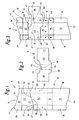
- the collar 12 consists of a separate blank ( Fig. 2 ).
- the elongate blank 13 is divided into panels by stamping lines and preferably embossed fold lines to form a box front wall 14, a bottom wall 15, a box back wall 16.
- Box side flaps 17, 18 are laterally attached to the box front panel 14. These are associated with corresponding, inner box side tabs 19, 20 in the region of the box rear wall 16.
- a blank area adjoining the box rear wall 16 is formed for the lid 11, namely with the lid rear wall 21, the end wall 22 and the lid front wall 23.
- Lateral tabs are also arranged in the area of the blank areas assigned to the lid 11.
- the blank 13 is therefore designed to use the Lticiansfalttamas.
- the box side flaps 17 and 19, and 18 and 20 are fully overlapped to form a box side wall 28.
- the box side flaps 18 and 20 are folded to cover and bonded together by glue an opposite box side wall. From the lid side tabs 24..27 lid side walls 30 and 31 are formed.
- a special feature is that the lid 11 in the region of a side wall via a hinge, namely via a line joint 32, hinged to the box part 10 is connected.
- the inner side flaps namely box side flaps 20 of the box rear wall 16 and lid side flaps 25 are connected together at the lid rear wall 21 and delimited from each other by a line joint 32 formed by embossing or otherwise.
- lid 11 and box part 10 are delimited from each other by closing edges, which - starting from the ends of the line joint 32 - to the opposite side, namely the box side wall 28 are inclined downwards.
- the closing edges consist of free, obliquely directed end edges 33, 34 of the blank 13.
- box rear wall 16 and lid rear wall 21 are separably connected to one another, by a slanted punching line 35 and Residual connections 36. These ensure a uniform blank 10 for the production of the package.
- the remaining connections 36 are severed, so that the punching line 35 forms a continuous separation between the box part 10 and lid 11.
- a continuous separating cut 37 is provided in the area of box side wall 28 and lid side wall 30 or in the area of box side tabs 19 and lid side tabs 24, so that in the region of the corresponding side walls 28, 30 box part 10 and lid 11 are separated from one another are.
- the collar 12 is designed such that the package contents, in the present case a cigarette block 37, that is to say a group of cigarettes surrounded by an inner blanket, are surrounded by the collar 12 all around.
- the collar 12 consists for this purpose of collar front wall 38, subsequent collar side wall 39, collar rear wall 40 and a peripheral collar side wall 41.
- collar front wall 38 Approximately in the middle of the collar side wall 39, within the collar 12 between the front wall 38 and Rear wall 40 is positioned, there is a recess 42 which in the finished package ( Fig. 5 ) in the region of the lid side wall 30 and in adjacent partial areas of the lid front wall 23 and the lid rear wall 21 extends.
- the folded collar 12 surrounds the cuboid cigarette block 37 such that the collar front wall 38 rests against the inside of the box front wall 14.
- the collar sidewall 39 faces the carton side wall 28 and the collar rear wall 40 of the carton rear wall 16.
- the attached as an end flap collar side wall 41 abuts against the box side wall 29.
- a closing aid for the cover 11 in the region of the lid side wall 30 is arranged.
- This consists of a tab or tongue 43 at the lower closing edge of the lid 11 and the lid side wall 30.
- a cooperating with this tongue 43 counter-member is formed on the collar 12 in matching relative position to the tongue 43. It is a recess in the collar side wall 39, in which the tongue 43 enters with the lid 11 in an upwardly directed position.
- the recess is formed in this case by a U- or C-shaped punch 44 to form an upwardly directed tab 45.
- This is pivotable about a transverse, lower line 46.
- the tab 45 is deformed slightly inwardly in the manufacture of the package, so that a U-shaped slot for the entry of the tongue 43 is formed.
- a special feature is the production of the package from two separate blanks. These are in the unfolded state or after folding only the tongue 43 against the inside of the lid side flap 26 merged into a unit by the collar 12 is placed in the pack relative position on the blank 10 (inside).
- the collar 12 is aligned with the collar back wall 40 aligned with the carton rear wall 16.
- the adjacent collar side wall 41 lies against the inner box side flap 20 and the opposite collar side wall 39 against the other box side flap 19 on.
- the collar front wall 38 projects laterally beyond the blank 10.
- the relative position is chosen such that an upper part of the collar 12 lies in the region of the cover 11 and thus protrudes out of the box part 10 in the finished package ( Fig. 5 ).
- For the closing aid namely for the tab 45 of the lid side tabs 24 is provided with a recess 47 which ensures the access of the arranged on the outer lid side tabs 26 tongue 43 to the counterpart of the entanglement on the collar 12.
- stops 81, 82 are formed, in the box side flap 20 on the one hand and in the box side flap 19 on the other. These are material deformations that are formed by punching and embossing, so that a stop edge is formed by the stops 81, 82 against which a (lower) edge of the collar 12 abuts, namely a lower edge of the collar side wall 41 on the one hand and the collar side wall 39, on the other hand.
- the stops 81, 82 are mounted by basically known punching and embossing tools.
- the collar 12 is fixed in the pack according to the positioning on the blank 13 by gluing, in the present case by a transverse row of glue dots 48, which extend over the full width of the blank 10 with at least one glue point 48 in the region of the box side tabs 19, 20. Further glue points 49 serve to fix the cigarette block 37 in the package.
- Unfolded blank unit 10, 12 is processed in a packaging machine to form a folding box.
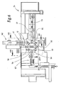
- the present example largely corresponds to a packaging machine known for the production of packages of the Hinge-Lid type with a folding turret 50, which is dish-shaped and can be rotated by means of an upright shaft 51 about a vertical axis.
- a plurality of pockets 52 are arranged, each for receiving a blank or a cutting unit including package contents.
- the folding turret 50 or outside the area of the same folding bodies are arranged, which fold the blank 10, 12 during the rotational movement to form the package.
- cigarettes for forming groups of cigarettes 53 are taken from a cigarette magazine 54 and fed to the folding turret 50 along a cigarette path in the radial direction.
- the cigarette group 53 is wrapped in an inner blank made of paper or Stanniol to form the cigarette block 37. This is inserted in a plug-in station 55 in there held bag 52 (with blank 13, 12).
- a Ausschubstation 56 On the opposite side of the folding turret 50 is a Ausschubstation 56 for transferring the largely finished packs to a radially laxative packing web 57.
- the blanks 13 are transported so that the side with the tongue 43 is directed forward. During transport, the tongue 43 is folded against the inside of the lid side flap 26, ie upwards.
- a special feature is the feeding of the individual blanks and transfer of the cutting unit to a pocket 52 in the region of an insertion station 58. This is offset by 90 ° to the stations 55, 56, that is arranged transversely to the conveying direction of the cigarette groups and packs.
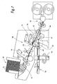
- the blanks 13 are conveyed along a blank path 59 guided above the revolver 50 to the introduction station 58 along a blank path 59 guided diametrically to the folding turret 50.
- the blanks 13 are removed individually from a blank magazine 60 and then transported in a manner known per se along the blank web 59 to a defined position above the pocket 52.
- the collars 12 are fed on a separate web, namely collar web 61, to the introduction station 58 or to the associated blank 13, specifically in a conveying direction opposite to the blank web 59. Furthermore, the collar web 61 is offset from the blank web 59 so that the collars 12 arrive at a position adjacent to the blank 13 being held ready.
- the blank web 59 is disposed above the folding turret 50 substantially in a downwardly inclined plane.
- the collar web 61 runs in a plane inclined upward in the conveying direction, namely slightly upwardly offset in height from the blank web 59.
- the collar web 61 adjoins a collar aggregate 62 outside or next to the packaging machine.
- the individual collars 12 are separated from a material web and introduced into the collar web 61. This consists in the region of the collar unit 62 of conveyor rollers, in the packaging machine essentially from (two pairs of) superimposed conveyor belts 63, 64. Between the conveyor troughs, the collar 12 are initially transported in sealing position, finally with distances from each other.
- a special collar unit is formed. This consists of an end plate 65 which extends in the transverse direction into the region of the conveyor belts 63, 64.
- the end plate 65 forms the adjusting stop for the collar 12, and here as a cross-sectionally U-shaped, transverse guide profile 66th
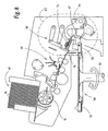
- the blank 13 is held in the insertion station 58 above a folding shaft 67 defined by molded bodies. This is located in the end region of the blank web 69.
- the blank 13 is aligned in a corresponding relative folding subsequent operation in lateral guides 68 in precise alignment with the pocket 52 located below the folding shaft 67.
- the collar 12 is moved at the end of the collar web 61 on the end plate 65 in the transverse direction.
- This is a special slide 69.
- This is provided with a holding member for detecting the collar 12, namely with a suction cup 70 which is connected via a suction line 71 to a vacuum source.
- the slider 69 detects the collar 12 with the sucker 70 at the top.
- a transverse stop 72 determines the position of the collar 12.
- the slider 69 returns after dropping the collar 12 in a slightly increased trajectory in the starting position to take over the next collar 12 back.
- a closed trajectory 73 of the slider 69 is shown by a dashed line.
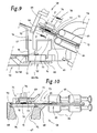
- Blank 13 and collar 12 are now in pack-oriented position over the folding shaft 67, initially spaced from each other ( Fig. 10 ).
- a folding member namely a folding plate 74 is first detected by downward movement of the collar 12 and then the blank 13 and taken in a downward folding movement.
- Parts of the blank 13 and of the collar 12 slide along fold guides 75 and 76 and are erected on the way to the pocket 52 located below the folding shaft 67.
- fold guides 75 are in particular the box side tabs 19 and 20 and the subsequent lid side tabs 24, 25 erected.
- the supply of the collar 12 in a folding position offset to the collar web 61 takes into account the present in the insertion station 58 folding organs, in particular the up and down movable folding plate 74.
- This is designed so that the slider 69, the collar 12 each in the folding position above the folding shaft 67th can transport.
- the folding plate 74 has for this purpose a lateral recess 77, in which the slider 69 in the end position above the folding shaft 67 occurs ( Fig. 10 ).
- the recess 77 is closed by a bell-shaped cover 78 upwards.
- the slider 69 can be solved in the end position of the collar 12, which fixed by the regions of the folding plate 74 outside of the recess 77 in the position above the blank 13 becomes. There is sufficient space for the slider 69 to return to the home position in a raised position before the folding plate 74 is moved downwardly.
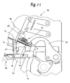
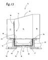
- the folding plate 74 After retraction of the slider 69 in the starting position, the folding plate 74 is moved downward, by a stationary pivot lever 79. The folding plate 74 pushes the blank 13 with collar 12 until it rests on a pocket bottom 80 of the pocket 52 (FIGS. Fig. 13 ).
- the Faltrevolver 50 promotes the pocket 52 without substantial change of the folding tabs in the insertion station 55.
- the cigarette block 37 is inserted in the radial direction in the pocket 52, the blanks in cross-section from Fig. 13 assume an obvious position.
- the pocket 52 is provided with retaining members for the (partially folded) blank 13 including collar 12. These are holding tongues 83, 84, which are arranged at the upper edge of the U-shaped pocket 52 and abut folded tabs of the blank 13 and the collar 12 folded upwards.
- the retaining tongue 84 bears against the free edges of the box side flap 20 and the collar side wall 41.
- the retaining tongue 83 is located in the region of the erected collar front wall 38.
- the collar 12 is designed such that the retaining tongue 83 bears against edges of the blank 13 and of the collar 12.
- a punching line 85 which is formed in the region of a folding line between the collar front wall 38 and the collar side wall 39 serves as the edge free incision. Due to corresponding deformation, the sharpened retaining tongue 83 reaches the contact position for fixing the unit.
- the largely completed pack is pushed out of the folding turret 50 in the area of the ejection station 56 and transferred to the packing web 57.
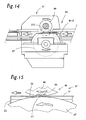
- a glue station 86 for applying glue to the underside of the laterally directed folding flaps, namely the box side flaps 17, 18 and the lid side flaps 26, 27. These are then up to the plant to the already folded inner Lateral tabs 19, 20, 24, 25 folded over.
- the glue station 86 is provided with a lower glue roller 87, which dips into a glue pot and transmits glue as a result of rotational movement to the underside of the folding flaps.
- the glue roller 87 cooperates with a pressure roller 88 arranged above the movement path of the folding tabs.
- This roller is provided with a recess 89 on its circumference.
- the recess 89 is located in the region of the folded into the detent position tongue 43, namely on the underside of the provided with glue lid side flap 26.
- the tongue 43 is already in the area of the blank web 59 in the operative position according to Fig. 3 folded.
- the collar 12 is attached to the blank 13 in the pack according to the relative position and connected to the blank 13 by gluing, preferably by glue, so that a fixed relative to the relative position unit can be inserted into the folding turret. Furthermore, a combination of blank 13 and collar 12 is carried out in advance, so that they are fed as a unit to the folding turret.
Landscapes
- Engineering & Computer Science (AREA)
- Mechanical Engineering (AREA)
- Wrapping Of Specific Fragile Articles (AREA)
Abstract
Claims (13)
- Procédé de fabrication de boîtes à couvercle rabattable avec une partie de boîte (10), un couvercle (11) et un col (12) pour un paquet de cigarettes (37), dans lequel la partie de boîte (10) et le couvercle (11) forment un coupon commun unitaire (13) et le col (12) est constitué par un coupon séparé, dans lequela) on positionne le col (12) sur le coupon déplié (13) dans une position relative convenant pour l'emballage et on l'assemble au coupon (13) par collage pour former une unité, etb) on envoie l'unité composée du coupon (13) avec le col (12) à une station d'introduction (58) d'une tourelle de pliage (50),caractérisé par la caractéristique suivante:c) on introduit ensuite l'unité composée du coupon (13) et du col (12) ensemble dans une cellule (52) de la tourelle de pliage (50) avec pliage partiel simultané du coupon (13) et du col (12).
- Procédé selon la revendication 1, caractérisé en ce que l'on assemble le col (12) au coupon (13) au moyen d'une série transversale de points de colle (48), avec chaque fois au moins un point de colle (48) dans la région des rabats latéraux de boîte (19, 20) du coupon (13).
- Procédé selon la revendication 1, caractérisé par les caractéristiques suivantes:a) on envoie les coupons (13) d'une part et les cols (12) d'autre part sur des voies séparées à la station d'introduction (58), à savoir une voie de coupons (59) d'une part et une voie de cols (61) d'autre part;b) dans la région de la station d'introduction (58), on guide un coupon (13) et un col (12) en application l'un sur l'autre dans une position relative convenant pour l'emballage;c) on introduit ensuite un coupon (13) et un col (12) ensemble, sous la forme d'une unité collée, dans une cellule (52) de la tourelle de pliage (50).
- Procédé selon la revendication 3, caractérisé par les caractéristiques suivantes:a) on décale ou on dispose à distance l'une de l'autre la voie de coupons (59) et la voie de cols (61) dans la direction de transport;b) dans la région de la station d'introduction (58), on transporte le col (12) par un mouvement transversal dans la position relative convenant pour l'emballage vers le coupon (13), en particulier dans un plan situé à faible distance au-dessus du coupon (13).
- Procédé selon la revendication 1 ou 3, caractérisé en ce que l'on dépose le col en position décalée sur la face intérieure du coupon (13), de telle manière qu'une paroi avant du col déborde latéralement au-delà du coupon (13), dans lequel le coupon (13) et le col (12) sont positionnés dans la cellule (52) de la tourelle de pliage (50) de telle manière que la paroi avant de col (38) dressée après l'introduction dans la cellule (52) soit disposée sur le côté de la cellule (52) situé vers l'avant dans le sens de rotation.
- Dispositif de fabrication de boîtes à couvercle rabattable notamment pour un paquet de cigarettes (37), se composant d'une partie de boîte (10), d'un couvercle (11) et d'un col (12), caractérisé par les caractéristiques suivantes:a) des coupons (13) d'une part et des cols (12) d'autre part peuvent être fournis à une station d'introduction commune (58) au-dessus d'une tourelle de pliage (50), le long de voies de transport séparées, à savoir une voie de coupons (59) et une voie de cols (61), de préférence avec une direction de transport opposée;b) la voie de coupons (59) s'étend immédiatement jusqu'à la station d'introduction (58) avec alignement du coupon (13) au-dessus de la cellule (52) de la tourelle de pliage (50);c) la voie de cols (61) s'étend en position décalée par rapport à la voie de coupons (59), de préférence dans un plan de transport légèrement plus élevé;d) dans la région de la station d'introduction (58), le col (12) peut être transporté par un mouvement transversal dans une position convenant pour l'emballage à faible distance au-dessus du coupon (13);e) un col (12) et un coupon (13) peuvent être introduits dans la cellule associée (52) au moyen d'un organe de pliage commun, notamment au moyen d'une plaque de pliage (74) mobile vers le bas.
- Dispositif selon la revendication 6, caractérisé en ce que les cols (12) découpés d'une bande peuvent être transportés au moyen de courroies transporteuses (63, 64) au moins dans une région partielle de la voie de cols (61), et en ce que le col (12) peut être transporté le long de la voie de cols (61) jusqu'à une butée d'extrémité et déplacé ensuite le long de la butée d'extrémité par un mouvement transversal dans la position convenant pour l'emballage au-dessus du coupon (13), de préférence sur une plaque d'extrémité (65) avec un profil de guidage orienté transversalement (66) comme butée d'extrémité.
- Dispositif selon la revendication 6 ou 7, caractérisé en ce que le col (12) est déplaçable transversalement au moyen d'un chariot (69) hors de la région de la voie de cols (61) jusque dans la position au-dessus du coupon (13), de préférence au moyen d'un suceur (70) disposé sur le chariot (69) pour saisir le col (12) par sa face supérieure.
- Dispositif selon la revendication 8, caractérisé en ce que le chariot (69) est déplaçable jusque dans la région de l'organe de pliage, à savoir de la plaque de pliage (74), dans lequel la plaque de pliage (74) présente un évidement (77) pour l'entrée temporaire du chariot (69) lors du transport transversal du col (12).
- Dispositif selon la revendication 6 ou l'une quelconque des autres revendications de dispositif, caractérisé en ce qu'un puits de pliage (67), réalisé par des guides de pliage essentiellement verticaux (75, 76), est formé au-dessus de la cellule (52) de la tourelle de pliage (50) dans la région de la station d'introduction (58), dans lequel le puits de pliage (67) ou des guides de pliage latéraux (75) présente(nt) des guidages (68) pour le coupon (13) et légèrement au-dessus pour le col (12).
- Dispositif selon la revendication 6 ou l'une quelconque des autres revendications de dispositif, caractérisé en ce que la cellule (52) de la tourelle de pliage (50) comporte des organes de maintien pour le coupon (13) partiellement plié y compris le col (12), à savoir des languettes de maintien (83, 84), qui sont disposés sur un bord supérieur de la cellule (52) de section transversale en forme de U et s'appliquent sur des faces orientées vers le haut de pattes pliées du coupon (13) ainsi que du col (12).
- Dispositif selon la revendication 6 ou l'une quelconque des autres revendications de dispositif, caractérisé en ce qu'une aile dressée du col (12), à savoir la paroi avant (38) du col, peut être pliée contre le côté supérieur du paquet de cigarettes (37) au moyen d'un organe de pliage fixe, par un mouvement de rotation de la tourelle de pliage (50), après l'introduction du coupon (13) avec le col (12) dans la cellule (52) et après l'insertion du paquet de cigarettes (37).
- Dispositif selon la revendication 6 ou l'une quelconque des autres revendications de dispositif, caractérisé en ce qu'un emballage largement terminé peut être extrait de la tourelle de pliage (50) et introduit dans une voie d'emballage (57) qui suit, dans lequel un module de collage avec un rouleau de collage inférieur (87) et un rouleau d'application supérieur (88) est disposé dans la région de la voie d'emballage (57) et le rouleau d'application (88) présente un évidement (89) dans la région de la languette pliée (43).
Applications Claiming Priority (2)
| Application Number | Priority Date | Filing Date | Title |
|---|---|---|---|
| DE102006021991A DE102006021991A1 (de) | 2006-05-10 | 2006-05-10 | Klappschachtel für Zigaretten sowie Verfahren und Vorrichtung zum Herstellen derselben |
| PCT/EP2007/003715 WO2007128435A2 (fr) | 2006-05-10 | 2007-04-27 | Boîte à couvercle rabattable pour cigarettes et procédé et dispositif de fabrication associés |
Publications (2)
| Publication Number | Publication Date |
|---|---|
| EP2016008A2 EP2016008A2 (fr) | 2009-01-21 |
| EP2016008B1 true EP2016008B1 (fr) | 2010-11-03 |
Family
ID=38137362
Family Applications (1)
| Application Number | Title | Priority Date | Filing Date |
|---|---|---|---|
| EP07724645A Ceased EP2016008B1 (fr) | 2006-05-10 | 2007-04-27 | Procédé et dispositif de fabrication de boîtes à couvercle rabattable pour cigarettes |
Country Status (3)
| Country | Link |
|---|---|
| EP (1) | EP2016008B1 (fr) |
| DE (2) | DE102006021991A1 (fr) |
| WO (1) | WO2007128435A2 (fr) |
Cited By (1)
| Publication number | Priority date | Publication date | Assignee | Title |
|---|---|---|---|---|
| EP4717613A1 (fr) * | 2024-09-25 | 2026-04-01 | G.D S.p.A. | Machine d'emballage et procédé d'emballage pour produire un paquet rigide pour articles à fumer avec un couvercle articulé |
Families Citing this family (11)
| Publication number | Priority date | Publication date | Assignee | Title |
|---|---|---|---|---|
| DE102008005407A1 (de) * | 2008-01-21 | 2009-07-23 | Focke & Co.(Gmbh & Co. Kg) | Verfahren und Vorrichtung zum Herstellen von Packungen für Zigaretten |
| US7845490B2 (en) | 2008-01-28 | 2010-12-07 | Philip Morris Usa Inc. | Side opening pack blank design |
| DE102008010433A1 (de) * | 2008-02-21 | 2009-08-27 | Focke & Co.(Gmbh & Co. Kg) | Verfahren und Vorrichtung zum Herstellen von Packungen für Zigaretten des Typs Klappschachtel |
| ITMO20080104A1 (it) * | 2008-04-14 | 2009-10-15 | Marco Vecchi | Mezzi di connessione per articoli |
| DE102008026450A1 (de) | 2008-06-03 | 2009-12-10 | Focke & Co.(Gmbh & Co. Kg) | Verfahren und Vorrichtung zur Herstellung von Zuschnitten für Zigarettenpackungen |
| DE102008027258A1 (de) | 2008-06-06 | 2009-12-10 | Focke & Co.(Gmbh & Co. Kg) | Verfahren und Vorrichtung zum Herstellen von Zigarettenpackungen |
| GB2488595A (en) * | 2011-03-04 | 2012-09-05 | British American Tobacco Co | Cigarette Pack with Recess and Locking Element |
| GB2498733A (en) | 2012-01-25 | 2013-07-31 | British American Tobacco Co | A Smoking Article Pack for Removing Articles Sideways |
| DE102013114642A1 (de) * | 2013-12-20 | 2015-06-25 | Focke & Co. (Gmbh & Co. Kg) | Verfahren und Vorrichtung zum Herstellen einer Verpackung für Produkte der Zigarettenindustrie |
| DE102014222994A1 (de) * | 2014-09-16 | 2016-03-17 | Focke & Co. (Gmbh & Co. Kg) | Packung für Zigaretten |
| DE102020132904A1 (de) * | 2020-12-10 | 2022-06-15 | Focke & Co. (Gmbh & Co. Kg) | Verfahren und Vorrichtung zur Herstellung von Zuschnitten für Kragen von Packungen für Zigaretten |
Family Cites Families (19)
| Publication number | Priority date | Publication date | Assignee | Title |
|---|---|---|---|---|
| US4034538A (en) | 1973-09-05 | 1977-07-12 | Alfred Schmermund | Method and apparatus for producing a container |
| DE2440006C2 (de) * | 1974-08-21 | 1984-06-28 | Focke & Co, 2810 Verden | Verfahren und Vorrichtung zum Herstellen von (quaderförmigen) Klappschachteln |
| DE2551427C2 (de) * | 1975-11-15 | 1987-02-19 | Focke & Co (GmbH & Co), 2810 Verden | Schachtel mit Klappdeckel |
| LU81675A1 (de) * | 1978-09-22 | 1979-12-07 | Reemtsma H F & Ph | Kappenfaltschachtel |
| DE3150447A1 (de) * | 1981-12-19 | 1983-06-30 | Focke & Co, 2810 Verden | Vorrichtung zum einfuehren von zigaretten-gruppen in zigaretten-packungen |
| CA2023664C (fr) | 1989-08-22 | 1997-03-18 | Klaus Peter Lamm | Boites pliantes a couvercle a charniere |
| DE3941844A1 (de) * | 1989-12-19 | 1991-06-20 | Focke & Co | Verfahren und vorrichtung zum herstellen von (zigaretten-)packungen |
| GB9008398D0 (en) * | 1990-04-12 | 1990-06-13 | Tabac Fab Reunies Sa | Novel cigarette pack |
| DE4122900A1 (de) * | 1991-07-11 | 1993-01-14 | Focke & Co | Klappschachtel fuer zigaretten |
| DE4141678A1 (de) * | 1991-12-17 | 1993-07-01 | Focke & Co | Verpackung aus karton sowie verfahren und vorrichtung zum herstellen derselben |
| GB9412819D0 (en) * | 1994-06-25 | 1994-08-17 | Imp Tobacco Co Ltd | Packs for smoking articles |
| DE19637259A1 (de) * | 1996-09-13 | 1998-03-19 | Focke & Co | Quaderförmige Verpackung für Zigaretten sowie Zuschnitt für die Verpackung |
| IT1309034B1 (it) * | 1999-03-09 | 2002-01-15 | Gd Spa | Metodo e dispositivo per la formazione di un pacchetto di sigarette |
| DE19938167A1 (de) | 1999-08-16 | 2001-02-22 | Focke & Co | Klappschachtel für Zigaretten |
| DE19945514A1 (de) | 1999-09-23 | 2001-03-29 | Focke & Co | Klappschachtel für Zigaretten |
| DE10208189A1 (de) | 2002-02-20 | 2003-09-04 | Schmermund Verpackungstechnik | Verfahren zum Verpacken von Zigaretten und Zigarettenpackung |
| DE60213782T2 (de) * | 2002-08-01 | 2007-08-09 | Europoligrafico S.P.A. | Kartonschachtel mit einem schwenkbaren Deckel |
| ITBO20040532A1 (it) | 2004-08-26 | 2004-11-26 | Aticarta S P A | Incarto rigido per articoli da fumo con coperchio incernierato collegato mediante incollatura |
| KR100698156B1 (ko) * | 2005-07-04 | 2007-03-22 | 엘지전자 주식회사 | 녹화물의 부분 블록 기능을 구비한 영상기기 및 그제어방법 |
-
2006
- 2006-05-10 DE DE102006021991A patent/DE102006021991A1/de not_active Withdrawn
-
2007
- 2007-04-27 WO PCT/EP2007/003715 patent/WO2007128435A2/fr not_active Ceased
- 2007-04-27 DE DE502007005561T patent/DE502007005561D1/de active Active
- 2007-04-27 EP EP07724645A patent/EP2016008B1/fr not_active Ceased
Cited By (1)
| Publication number | Priority date | Publication date | Assignee | Title |
|---|---|---|---|---|
| EP4717613A1 (fr) * | 2024-09-25 | 2026-04-01 | G.D S.p.A. | Machine d'emballage et procédé d'emballage pour produire un paquet rigide pour articles à fumer avec un couvercle articulé |
Also Published As
| Publication number | Publication date |
|---|---|
| DE102006021991A1 (de) | 2007-11-15 |
| EP2016008A2 (fr) | 2009-01-21 |
| WO2007128435A2 (fr) | 2007-11-15 |
| DE502007005561D1 (de) | 2010-12-16 |
| WO2007128435A3 (fr) | 2008-01-03 |
Similar Documents
| Publication | Publication Date | Title |
|---|---|---|
| EP2016008B1 (fr) | Procédé et dispositif de fabrication de boîtes à couvercle rabattable pour cigarettes | |
| EP2125573B1 (fr) | Procédé de fabrication d'emballages pour cigarettes | |
| EP2234891B1 (fr) | Procédé de fabrication d'emballages pour cigarettes | |
| EP2311632B1 (fr) | Emballage de cigarettes ainsi que procédé et dispositif de fabrication de celui-ci | |
| EP1829783B1 (fr) | Dispositif et procédé de fabrication d'emballages doubles | |
| EP3169592A1 (fr) | Procédé et dispositif de fabrication de paquets, en particulier de paquets de cigarettes | |
| DE2440006A1 (de) | Verfahren und vorrichtung zum herstellen und fuellen von klappschachteln aus faltbarem werkstoff, vorzugsweise fuer zigaretten | |
| EP2562092A1 (fr) | Dispositif et procédé de fabrication d'emballages pour cigarettes | |
| EP3366595A1 (fr) | Procédé et dispositif de fabrication de paquets (de cigarettes) | |
| DE102015010493A1 (de) | Verfahren und Vorrichtung zum Herstellen von (Zigaretten-)Packungen des Typs Kappenschachtel | |
| EP0550406A1 (fr) | Procédé et dispositif pour la fabrication d'emballages (pour cigarettes) | |
| EP2130773B1 (fr) | Dispositif et procédé de fabrication d'emballages de cigarettes | |
| EP2560883B1 (fr) | Dispositif et procede pour fabriquer des paquets de cigarettes | |
| EP1023991B1 (fr) | Procédé et machine pour fabriquer des paquets de cigarettes | |
| EP2746166B1 (fr) | Procédé et dispositif de fabrication d'un emballage pour cigarettes | |
| EP3248903B1 (fr) | Emballage de cigarettes, dispositif et procédé de fabrication | |
| EP2030896B1 (fr) | Procédé et dispositif de fabrication de paquets de cigarettes à couvercle articulé | |
| DE102006047812A1 (de) | Verfahren und Vorrichtung zum Herstellen von (Zigaretten-)Packungen | |
| DE102016004930A1 (de) | Packung für Zigaretten sowie Verfahren und Vorrichtung zum Herstellen derselben | |
| EP2690033B1 (fr) | Boîte en carton à couvercle rabattable | |
| WO2021009278A1 (fr) | Procédé et dispositif de manipulation d'une ébauche constituée d'un matériau de forme stable | |
| DE202015005169U1 (de) | Klappschachtel für Zigaretten | |
| DE2463378C2 (de) | Vorrichtung zum Herstellen von Packungen, insbesondere Klappschachteln |
Legal Events
| Date | Code | Title | Description |
|---|---|---|---|
| PUAI | Public reference made under article 153(3) epc to a published international application that has entered the european phase |
Free format text: ORIGINAL CODE: 0009012 |
|
| 17P | Request for examination filed |
Effective date: 20081024 |
|
| AK | Designated contracting states |
Kind code of ref document: A2 Designated state(s): AT BE BG CH CY CZ DE DK EE ES FI FR GB GR HU IE IS IT LI LT LU LV MC MT NL PL PT RO SE SI SK TR |
|
| AX | Request for extension of the european patent |
Extension state: AL BA HR MK RS |
|
| TPAC | Observations by third parties |
Free format text: ORIGINAL CODE: EPIDOSNTIPA |
|
| DAX | Request for extension of the european patent (deleted) | ||
| RBV | Designated contracting states (corrected) |
Designated state(s): DE GB IT |
|
| 17Q | First examination report despatched |
Effective date: 20090831 |
|
| GRAP | Despatch of communication of intention to grant a patent |
Free format text: ORIGINAL CODE: EPIDOSNIGR1 |
|
| RTI1 | Title (correction) |
Free format text: METHOD AND DEVICE FOR THE PRODUCTION OF HINGE-LID BOXES FOR CIGARETTES |
|
| GRAS | Grant fee paid |
Free format text: ORIGINAL CODE: EPIDOSNIGR3 |
|
| GRAA | (expected) grant |
Free format text: ORIGINAL CODE: 0009210 |
|
| AK | Designated contracting states |
Kind code of ref document: B1 Designated state(s): DE GB IT |
|
| REG | Reference to a national code |
Ref country code: GB Ref legal event code: FG4D Free format text: NOT ENGLISH |
|
| REF | Corresponds to: |
Ref document number: 502007005561 Country of ref document: DE Date of ref document: 20101216 Kind code of ref document: P |
|
| PLBE | No opposition filed within time limit |
Free format text: ORIGINAL CODE: 0009261 |
|
| STAA | Information on the status of an ep patent application or granted ep patent |
Free format text: STATUS: NO OPPOSITION FILED WITHIN TIME LIMIT |
|
| 26N | No opposition filed |
Effective date: 20110804 |
|
| REG | Reference to a national code |
Ref country code: DE Ref legal event code: R097 Ref document number: 502007005561 Country of ref document: DE Effective date: 20110804 |
|
| PGFP | Annual fee paid to national office [announced via postgrant information from national office to epo] |
Ref country code: GB Payment date: 20160427 Year of fee payment: 10 |
|
| GBPC | Gb: european patent ceased through non-payment of renewal fee |
Effective date: 20170427 |
|
| PG25 | Lapsed in a contracting state [announced via postgrant information from national office to epo] |
Ref country code: GB Free format text: LAPSE BECAUSE OF NON-PAYMENT OF DUE FEES Effective date: 20170427 |
|
| PGFP | Annual fee paid to national office [announced via postgrant information from national office to epo] |
Ref country code: DE Payment date: 20180426 Year of fee payment: 12 |
|
| PGFP | Annual fee paid to national office [announced via postgrant information from national office to epo] |
Ref country code: IT Payment date: 20180420 Year of fee payment: 12 |
|
| REG | Reference to a national code |
Ref country code: DE Ref legal event code: R119 Ref document number: 502007005561 Country of ref document: DE |
|
| PG25 | Lapsed in a contracting state [announced via postgrant information from national office to epo] |
Ref country code: DE Free format text: LAPSE BECAUSE OF NON-PAYMENT OF DUE FEES Effective date: 20191101 |
|
| PG25 | Lapsed in a contracting state [announced via postgrant information from national office to epo] |
Ref country code: IT Free format text: LAPSE BECAUSE OF NON-PAYMENT OF DUE FEES Effective date: 20190427 |