EP2016215B1 - Verbundfaser und zugehöriges nachweissystem - Google Patents
Verbundfaser und zugehöriges nachweissystem Download PDFInfo
- Publication number
- EP2016215B1 EP2016215B1 EP07732613A EP07732613A EP2016215B1 EP 2016215 B1 EP2016215 B1 EP 2016215B1 EP 07732613 A EP07732613 A EP 07732613A EP 07732613 A EP07732613 A EP 07732613A EP 2016215 B1 EP2016215 B1 EP 2016215B1
- Authority
- EP
- European Patent Office
- Prior art keywords
- fibre
- component
- composite
- components
- fibres
- Prior art date
- Legal status (The legal status is an assumption and is not a legal conclusion. Google has not performed a legal analysis and makes no representation as to the accuracy of the status listed.)
- Not-in-force
Links
Images



Classifications
-
- D—TEXTILES; PAPER
- D02—YARNS; MECHANICAL FINISHING OF YARNS OR ROPES; WARPING OR BEAMING
- D02G—CRIMPING OR CURLING FIBRES, FILAMENTS, THREADS, OR YARNS; YARNS OR THREADS
- D02G3/00—Yarns or threads, e.g. fancy yarns; Processes or apparatus for the production thereof, not otherwise provided for
- D02G3/44—Yarns or threads characterised by the purpose for which they are designed
- D02G3/441—Yarns or threads with antistatic, conductive or radiation-shielding properties
-
- D—TEXTILES; PAPER
- D02—YARNS; MECHANICAL FINISHING OF YARNS OR ROPES; WARPING OR BEAMING
- D02G—CRIMPING OR CURLING FIBRES, FILAMENTS, THREADS, OR YARNS; YARNS OR THREADS
- D02G3/00—Yarns or threads, e.g. fancy yarns; Processes or apparatus for the production thereof, not otherwise provided for
- D02G3/22—Yarns or threads characterised by constructional features, e.g. blending, filament/fibre
- D02G3/26—Yarns or threads characterised by constructional features, e.g. blending, filament/fibre with characteristics dependent on the amount or direction of twist
- D02G3/28—Doubled, plied, or cabled threads
-
- G—PHYSICS
- G01—MEASURING; TESTING
- G01B—MEASURING LENGTH, THICKNESS OR SIMILAR LINEAR DIMENSIONS; MEASURING ANGLES; MEASURING AREAS; MEASURING IRREGULARITIES OF SURFACES OR CONTOURS
- G01B11/00—Measuring arrangements characterised by the use of optical techniques
- G01B11/16—Measuring arrangements characterised by the use of optical techniques for measuring the deformation in a solid, e.g. optical strain gauge
- G01B11/18—Measuring arrangements characterised by the use of optical techniques for measuring the deformation in a solid, e.g. optical strain gauge using photoelastic elements
-
- Y—GENERAL TAGGING OF NEW TECHNOLOGICAL DEVELOPMENTS; GENERAL TAGGING OF CROSS-SECTIONAL TECHNOLOGIES SPANNING OVER SEVERAL SECTIONS OF THE IPC; TECHNICAL SUBJECTS COVERED BY FORMER USPC CROSS-REFERENCE ART COLLECTIONS [XRACs] AND DIGESTS
- Y10—TECHNICAL SUBJECTS COVERED BY FORMER USPC
- Y10T—TECHNICAL SUBJECTS COVERED BY FORMER US CLASSIFICATION
- Y10T428/00—Stock material or miscellaneous articles
- Y10T428/249921—Web or sheet containing structurally defined element or component
- Y10T428/249924—Noninterengaged fiber-containing paper-free web or sheet which is not of specified porosity
-
- Y—GENERAL TAGGING OF NEW TECHNOLOGICAL DEVELOPMENTS; GENERAL TAGGING OF CROSS-SECTIONAL TECHNOLOGIES SPANNING OVER SEVERAL SECTIONS OF THE IPC; TECHNICAL SUBJECTS COVERED BY FORMER USPC CROSS-REFERENCE ART COLLECTIONS [XRACs] AND DIGESTS
- Y10—TECHNICAL SUBJECTS COVERED BY FORMER USPC
- Y10T—TECHNICAL SUBJECTS COVERED BY FORMER US CLASSIFICATION
- Y10T428/00—Stock material or miscellaneous articles
- Y10T428/29—Coated or structually defined flake, particle, cell, strand, strand portion, rod, filament, macroscopic fiber or mass thereof
- Y10T428/2913—Rod, strand, filament or fiber
- Y10T428/2929—Bicomponent, conjugate, composite or collateral fibers or filaments [i.e., coextruded sheath-core or side-by-side type]
Definitions
- This invention relates to detection systems incorporating optical fibres, to components of the detection system, and to assemblies and structures incorporating these components.
- the present invention in at least some of its embodiments, addresses the above described problems and desires.
- an auxetic composite fibre including at least a first and a second component, wherein at least one of the components is an optical fibre, and the components are intertwined, in which the first component is helically wound around the second component, and there is a difference in the modulus of elasticity of the first and second components so that the application of a longitudinal strain causes helical deformation of said components.
- an optical fibre in an auxetic composite fibre of this type can result in an amplification of the variation of light transmission observed when the composite fibre is subjected to various perturbations, such as applied strain, lateral compression, torque or bending forces.
- composite fibres of the invention can be incorporated conveniently into a variety of locations and materials.
- the term "intertwined” includes within its scope wound, twisted and interlaced configurations. Without wishing to be limited by any particular theory, it is believed that relatively large variations in light transmission are caused by changes in path length and angle associated with perturbed composite fibres of the invention.
- the composite fibre defines a pathway, and it is believed (again without wishing to be limited by any particular theory) that the application of a force, such as a strain, compression or torsional force, to the composite fibre causes a displacement of the optical fibre away from or towards the pathway adopted by the composite fibre.
- a force such as a strain, compression or torsional force
- the moduli of elasticity of the first and second components are sufficiently different to enable such "off-axis" displacement of the optical fibre away from or towards the pathway adopted by the composite fibre to occur.
- the modulus of elasticity of the first component is greater than the modulus of elasticity of the second component.
- the first component and the second component may extend generally longitudinally relative to an axis, and variation in a tensile or compressive load applied to the first component causes the radial position of the second component relative to the axis to vary.
- the composite fibre may adopt a non-linear confirmation and/or forces other than tensile or compressive forces might be applied thereto.
- the first component is helically wound around the second component, and optionally the second component is helically wound around the first component.
- the first component may be wound around or otherwise intertwined with the second component and one or more further components.
- the second component may be wound around or otherwise intertwined with the first component and one or more further components.
- the optical fibre may intertwine with two components in a zigzag conformation. The intertwining may take the form of looping the optical fibre around one of the two components, passing the optical fibre across to the second of the two components, looping the optical fibre around the second of the two components, and passing the optical fibre back across to the first of the two components, the process being repeated a desired number of times.
- the first component is helically wound around the second component, and the resultant fibre is an auxetic fibre that displays auxetic properties.
- auxetic materials are materials that have a negative or effectively negative Poisson's ratio. In contrast to most conventional materials, auxetic materials possess the property that under a tensile load the material expands perpendicularly to the axis along which the tensile load is applied. In other words, auxetic materials expand as they are stretched. Conversely, materials are also auxetic if a compressive load applied along an axis results in a reduction in the dimension of the material along an axis perpendicular to the axis along which the compressive load is applied.
- the first component may be an optical fibre.
- the second component may be an elastomeric or non-elastomeric foam.
- the second component may be an optical fibre. It is possible that both first and second components might be optical fibres if optical fibres having suitable mechanical properties, in particular suitable moduli of elasticity are used.
- the radius of the second component may exceed that of the first component, and may exceed the radius of the first component by a factor of at least 10, preferably at least 100.
- a wound composite fibre may include, in addition to the first component, one or more further components which are wound around the second component.
- One or more of the further components may be a further optical fibre.
- a wound composite fibre may be counter-wound, i.e. one component may be wound along the other component with one handedness (e.g. in a clockwise manner), and counter-wound back along the other component with the other handedness (e.g. in an anti-clockwise manner).
- the optical fibre may be a fibre Bragg grating.
- the term 'fibre Bragg grating' is well known in the art of fibre optics, and is used herein to denote an optical fibre having one or more Bragg diffraction gratings formed therein.
- the Bragg grating(s) is formed by a variation in the effective refractive index of the core of the optical fibre, and may be periodic or aperiodic.
- the fibre Bragg grating may be a chirped fibre Bragg grating, i.e. a fibre Bragg grating in which the Bragg wavelength varies with position along the optical fibre.
- the optical fibre may be a polymer optical fibre or a silica optical fibre. Other materials or combinations of materials might be used.
- Composite fibres of the invention have many applications, some of which are described below.
- fibres might be used in the construction of toys and games wherein physical events may trigger other events.
- a physical strike may be detected using the composite fibre, and the detection of the strike may trigger a sound, a points score, a light signal or other display, or some other event.
- a fibrous assembly including at least two auxetic composite fibres wherein each of said composite fibres includes at least a first and a second component, wherein at least one of the components is an optical fibre, and the components are intertwined, in which the first component is helically wound around the second component, and there is a difference in the modulus of elasticity of the first and second components so that the application of a longitudinal strain causes helical deformation of said components.
- the at least two composite wound fibres may incorporate any aspect of the first aspect of the invention.
- the fibrous assembly consists essentially of a pair of the composite fibres disposed alongside one another.
- the fibrous assembly includes three or more composite fibres arranged alongside each other so as to form a sheet-like assembly.
- the fibrous assembly includes a bundle or three or more composite fibres which extend In a common direction.
- each of the wound fibres in the bundle is disposed alongside at least two of the other composite fibres.
- the first components of adjacent composite fibres may be wrapped around their respective second components with opposite handidness.
- the fibrous assembly may further include one or more core components disposed so as to separate two or more composite fibres.
- a fibrous assembly consisting essentially of a pair of composite fibres disposed alongside one another may further comprise a core component separating said pair of composite fibres.
- a bundle of three or more composite is arranged peripherally around a core component.
- a composite material having embedded therein at least one composite fibre of the first aspect of the invention and/or at least one fibrous assembly of the second aspect of the invention.
- the composite fibres and/or fibrous assemblies are incorporated into a fibrous structure, a resin is added to the fibrous structure, and the resin is cured to produce a composite material.
- the fibrous structure may comprise carbon fibre or other high strength fibres, and may be in the form of a mat.
- Composite structures of the invention can be used in a variety of applications, such as aircraft bodies and wings, toys and games.
- a fabric including at least one composite fibre of the first aspect of the invention and/or at least one fibrous assembly of the second aspect of the invention.
- the composite fibre and/or fibrous assembly forms part of the integrated structure of the fabric (as opposed to, for example, being attached to an integrated fabric structure).
- the fabric may be produced by any suitable technique such as weaving, knitting, braiding or tufting.
- the fabric may be, or comprise part of, an item of clothing.
- the item of clothing could be used for the control of remote equipment, or in conjunction with interactive games or virtual reality software.
- the items of clothing could be used for sports science or medical purposes in order to analyse the bodily movements of people or animals.
- the item of clothing is a glove, although other items of clothing, such as a body suit, trousers or leggings, shoes, t-shirts, shirts or other garments for the upper or lower body, are possible.
- a detection system including:
- the detection system further includes analysis means for deriving a physical variable that perturbs the at least one composite fibre, or a variation therein, from the electromagnetic radiation detected by the detection means, or a variation in said electromagnetic radiation.
- the analysis means may comprise a suitably programmed computer or microprocessor.
- the analysis means derives the strain or compressive load applied to the at least one composite fibre, or a variation therein.
- the analysis means derives the torque applied to the at least one composite fibre, or a variation therein.
- the analysis means derives the position at which a force is applied to the at least one composite and/or a conformation adopted by the at least one composite fibre in response to the applied force.
- the optical fibre may be a fibre Bragg grating, preferably a chirped fibre Bragg grating.
- the detection means may include an optical filter, preferably a narrow bandgap filter. Thin-film coatings may be used to provide the desired filtering properties.
- An optical filter may be used instead of, or in addition to, a fibre Bragg grating optical fibre.
- the detection system may include at least two auxetic composite fibres, and the analysis means may be adapted to derive the position at which a force is applied to the composite fibres and/or a conformation adapted by the composite fibres in response to the applied force by comparing the electromagnetic radiation emanating from the optical fibres, or comparing variations in the electromagnetic radiation emanating from the optical fibres.
- the analysis means may utilise an ab initio calculation to derive these data from the comparison, e.g. taking into account the different path lengths of the optical fibres resulting from the application of the force.
- artificial intelligence such as a neural network, may be used to derive the position at which the force is applied and/or the conformation adopted.
- the analysis means may be adapted to derive the degree of bend, for example a radius of curvature, of the composite fibres.
- the optical fibres of a pair of auxetic composite fibres have first ends located in one region and second ends located in another region spaced apart from the first ends, and the means for directing electromagnetic radiation directs electromagnetic radiation into the optical fibre of one composite fibre in the pair at the first end thereof, and directs electromagnetic radiation into the optical fibre of the other composite fibre in the pair at the second end thereof so that electromagnetic radiation in one composite fibre travels in an opposite direction to electromagnetic radiation in the other composite fibre in the pair.
- the pair of composite fibres are substantially parallel, and electromagnetic radiation is directed into the optical fibres from opposite ends. In this way, the position at which a force is applied and/or a conformation adopted may be derived by comparing the chirp of the optical fibres in the pair of composite fibres.
- a method of detecting a physical variable including the steps of:
- Figure 1 shows a helically wound fibre 10 of the invention which comprises a first component 12 and a second component 14.
- the first component 12 is an optical fibre, which is wound around the periphery of the second component 14 forming a helix.
- the first component is provided around the second component through one or more turns, the one or more turns being spaced longitudinally relative to an axis defined by the second component.
- the wrapping of the first component 12 around the second component 14 causes a deformation of the second component 14 from a generally linear configuration to a helical configuration.
- Figure 2 shows a conformation adopted by the helically wound fibre 10 when subjected to a longitudinal strain.
- the application of positive longitudinal strain causes the first component 12 to become less deformed, and thus light transmission increases with increasing strain.
- the non-optical fibre component (whether this is the first component 12 or the second component 14) may be constructed from an elastomeric or plastic material, It is also possible to utilise fibres in which both the first component 12 and second component 14 are optical fibres. Irrespective of which component is an optical fibre, there should be a difference in the modulus of elasticity of the components, so that the application of a longitudinal strain causes helical deformation of the components. Further details concerning the fundamental principles of helically wrapped auxetic fibres can be found in WO 2006/021763 and WO 2004/088015 .
- FIG. 3 shows a detection system, depicted generally at 20, which incorporates a fibre 22 of the invention.
- the detection system 20 further comprises a light source 24, for directing light into one end of the optical fibre contained in the fibre 22.
- the light source 24 can be of any suitable type, such as a laser or LED, and light of any suitable wavelength or range of wavelengths might be utilised, such as ultraviolet, visible or infrared radiation.
- a suitable detector 26 such as a light-to-voltage sensor is positioned adjacent the other end of the optical fibre, and detects light transmitted along the optical fibre.
- the output of the detector 26 is monitored by analysis means 28, which is calibrated or otherwise adapted to equate the measured light transmission with a perturbation to the fibre 22, such as an increase or decrease in an applied longitudinal strain.
- the application of torque to a fibre of the invention produces a measurable change in light transmission through the optical fibre.
- the present invention can be used as a torque sensor.
- a fibre of the invention consisting of a 1000 ⁇ m Super Eska(RTM) communications optical fibre helically wrapped around a core elastomer (8 mm "bungee” cord).
- a red (650 nm) LED was used as a light source to introduce light into the optical fibre.
- Light emanating from the other end of the optical fibre was detected with a fibre optic test set manufactured by Industrial Fibre Optics. It is common for the core fibre to be significantly bigger than the other fibre. In other representative examples the diameter of the optical fibre is around 250 microns and the diameter of the core is 1 mm or more.
- a plurality of fibres of the invention which incorporate optical fibres may be combined into a more complex structure.
- a pair of fibres are disposed alongside each other in a substantially parallel configuration.
- the fibres may or may not be spaced apart by a core component.
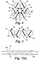
- Figure 4 shows a bundle structure 40 which comprises a plurality of auxetic fibres of the invention circumferentially arranged around a central axis.
- Each fibre comprises a first component 42 and a second component 44.
- the stripes 46 shown in Figure 4 indicate the direction of wrapping of the first component 42 around the second component 44, i.e., the handidness of the fibre.
- adjacent fibres in the bundle are wrapped in opposite directions.
- the fibres are arranged peripherally around a core component 48, although it is also possible to utilise embodiments in which there is no core component.
- Figure 5 shows another complex structure 50 in the form of a flat "tape" comprising a plurality of fibres of the invention arranged alongside each other in a planar configuration.
- Each fibre comprises a first component 52 and a second component 54.
- the stripes 56 shown in Figure 5 indicate the wrapping direction in the same manner as the stripes 46 shown in Figure 4 , and similar comments concerning adjacent fibres apply. It is also possible to utilise large numbers of substantially parallel fibres in order to produce a sheet-like structure.
- Fibres and/or more complex structures of the invention can be incorporated into larger structures in a number of ways.
- a fabric can be produced utilising fibres of the present invention as yarns. Fabric production techniques such as weaving, knitting or braiding might be utilised for this purpose.
- a composite material is made by incorporating fibres and/or more complex structures in the lay-up process, followed by the introduction of a resin thereto. The resin is subsequently cured to produce the composite material.
- fibres of the invention can be incorporated into mats of carbon fibre (or other high strength fibres) or laid in between mats of carbon fibre, which are subsequently treated with a resin which is cured to produce the composite material.
- Such structures have numerous applications, such as in the production of aircraft wings.
- a further advantage is that information can be obtained from the optical fibre sensors during the curing of the resin, thereby providing information as to whether the curing process has been completed satisfactorily.
- Other application areas for embedded fibres of the invention include other aircraft components, such as the fuselage, bridges and buildings. The fibres could then remain in place throughout the lifetime of the structure, enabling structural health to be monitored.
- the present invention can be used to determine the position at which a physical perturbation to the fibre occurs and/or the confirmation adopted by the structure in response to an applied force.
- Figure 6 shows an example in which a flat "tape" 60 of fibres of the invention is bent so as to adopt the configuration of an arc.
- the radius of curvature of an fibre 62 disposed on the inside of the arc is less than the radius of curvature of an fibre 64 disposed on the outside of the arc. Therefore, when the tape 60 is subjected to a bending force causing the tape 60 to adopt the arc configuration shown in Figure 6 , the outer fibre 64 has a longer path length than the path length of the inner fibre 62.
- a perturbation applied to the fibre Bragg grating at a given position will principally affect the Bragg grating present at this position, which can be identified by the detection system from the characteristic Bragg wavelength.
- the perturbation to the system may be manifest in a variation in the Bragg wavelength of the Bragg grating at or near to the position of the perturbation.
- the detection technique employed in the present invention may not simply comprise a measurement of variation in transmitted light intensity.
- Other properties of the light directed into the optical fibre such as the wavelength distribution of light emerging from the optical fibre might be detected. For example, variations in the Bragg wavelength of one or more Bragg gratings formed in the optical fibre might be detected.
- Figure 7 shows a further embodiment in which the position of a perturbation is determined.
- a pair of parallel fibres 70, 72 are employed, and a light source or sources are utilised so as to direct light into the optical fibre 70a of fibre 70 from one direction and to introduce light into the optical fibre 72a of fibre 72 from the opposite direction.
- a light source or sources are utilised so as to direct light into the optical fibre 70a of fibre 70 from one direction and to introduce light into the optical fibre 72a of fibre 72 from the opposite direction.
- light travels along the optical fibres 70a, 72a in an essentially anti-parallel fashion, and emerges from opposite ends of the optical fibres 70a, 72a to be detected by suitable detection means.
Landscapes
- Engineering & Computer Science (AREA)
- Mechanical Engineering (AREA)
- Textile Engineering (AREA)
- Physics & Mathematics (AREA)
- General Physics & Mathematics (AREA)
- Optical Transform (AREA)
- Length Measuring Devices By Optical Means (AREA)
- Treatment Of Fiber Materials (AREA)
- Eye Examination Apparatus (AREA)
- Acyclic And Carbocyclic Compounds In Medicinal Compositions (AREA)
- Geophysics And Detection Of Objects (AREA)
Claims (13)
- Instabile, zusammengesetzte Faser (10), die wenigstens eine erste Komponente (12) und eine zweite Komponente (14) aufweist, wobei wenigstens eine der Komponenten eine optische Faser ist und die Komponenten miteinander verflochten sind, indem die erste Komponente schraubenförmig um die zweite Komponente gewickelt ist, und wobei eine Differenz im Elastizitätsmodul der ersten und der zweiten Komponenten derart besteht, daß die Einwirkung einer Längsspannung eine schraubenförmige Verformung der Komponenten bewirkt.
- Zusammengesetzte Faser nach Anspruch 1, dadurch gekennzeichnet, daß der Elastizitätsmodul der ersten Komponente größer ist als der Elastizitätsmodul der zweiten Komponente.
- Zusammengesetzte Faser nach Anspruch 1 oder 2, dadurch gekennzeichnet, daß die optische Faser eine polymere optische Faser ist oder eine optische Siliziumoxidfaser ist.
- Faserige Anordnung (40), die wenigstens zwei instabile zusammengesetzte Fasern aufweist, wobei jede dieser zusammengesetzten Fasern mit wenigstens einer ersten Komponente (42) und einer zweiten Komponente (44) versehen ist und wobei wenigstens eine der Komponenten eine optische Faser ist und die Komponenten miteinander verflochten sind, so daß die erste Komponente schraubenförmig um die zweite Komponente gewickelt ist, und wobei eine Differenz im Elastizitätsmodul der ersten und der zweiten Komponenten besteht, so daß die Einwirkung einer Längsspannung eine schraubenförmige Verformung der Komponenten bewirkt.
- Zusammengesetztes Material, in dem wenigstens eine zusammengesetzte Faser gemäß einem der Ansprüche 1 bis 3 und / oder wenigstens eine Faseranordnung gemäß Anspruch 4 eingebettet ist.
- Gewebe mit wenigstens einer zusammengesetzten Faser gemäß einem der Ansprüche 1 und 3 und / oder wenigstens einer Faseranordnung gemäß Anspruch 4.
- Nachweissystem (20), umfassend wenigstens eine instabile, zusammengesetzte Faser (22) mit wenigstens einer ersten und einer zweiten Komponenten, wobei wenigstens eine der Komponenten eine optische Faser ist und die Komponenten miteinander verflochten sind, und wobei die erste Komponente schraubenförmig um die zweite Komponente gewickelt ist und eine Differenz in dem Elastizitätsmodul der ersten und der zweiten Komponenten gegeben ist, so daß die Einwirkung einer Längsspannung eine schraubenförmige Verformung der Komponenten bewirkt; ferner umfassend eine Einrichtung (24) zur Lenkung einer elektromagnetischen Strahlung entlang der optischen Faser; des weiteren eine Nachweiseinrichtung (26) zur Feststellung der elektromagnetischen Strahlung, die aus der optischen Faser austritt; und eine Analyseeinrichtung (28) zur Ableitung einer physikalischen veränderlichen Größe, die die wenigstens eine zusammengesetzte Faser stört oder eine Veränderung in ihr, und zwar von der elektromagnetischen Strahlung, die durch die Nachweiseinrichtung nachgewiesen wird oder einer Veränderung in dieser elektromagnetischen Strahlung.
- Nachweissystem nach Anspruch 7, dadurch gekennzeichnet, daß die Analyseeinrichtung die Spannung, das Drehmoment oder die Druckkraft herleitet, die auf die wenigstens eine zusammengesetzte Faser oder eine Abweichung in ihr einwirkt.
- Nachweissystem nach Anspruch 7, dadurch gekennzeichnet, daß die Analyseeinrichtung die Position herleitet, bei der eine Kraft auf die wenigstens eine zusammengesetzte Faser und / oder eine Gestaltung einwirkt, welche durch die wenigstens eine zusammengesetzte Faser aufgrund der einwirkenden Kraft angenommen wird.
- Nachweissystem nach Anspruch 9, dadurch gekennzeichnet, daß wenigstens zwei instabile zusammengesetzte Fasern (70, 72) vorhanden sind, bei denen die Analyseeinrichtung die Position ableiten kann, bei der auf die zusammengesetzte Fasern und / oder eine Gestaltung, die von den zusammengesetzten Fasern angenommen wird, eine Kraft einwirkt, und zwar in Abhängigkeit von der aufgebrachten Kraft, indem die elektromagnetische Strahlung, die von den optischen Fasern ausgeht, verglichen wird oder die Veränderungen in der elektromagnetischen Strahlung verglichen werden, die von den optischen Fasern ausgehen.
- Nachweissystem nach Anspruch 10, dadurch gekennzeichnet, daß die Analyseeinrichtung den Grad der Biegung der zusammengesetzten Fasern herleiten kann.
- Nachweissystem nach Anspruch 10 oder Anspruch 11, dadurch gekennzeichnet, daß die optischen Fasern eines Paares instabiler zusammengesetzter Fasern (70, 72) erste Enden aufweisen, die in einem Bereich liegen, und zweite Enden, die in einem anderen Bereich liegen, der von den ersten Enden mit Abstand getrennt ist, und daß die Einrichtung zur Ausrichtung elektromagnetischer Strahlung die elektromagnetische Strahlung in die optische Faser oder eine zusammengesetzte Faser des Paares lenkt, und zwar an einem ersten Ende der Faser, und daß sie die elektromagnetische Strahlung in die eine optische Faser oder die andere zusammengesetzte Faser des Paares an dem zweiten Faserende hineinlenkt, so daß die elektromagnetische Strahlung in einer zusammengesetzten Faser in einer entgegengesetzten Richtung zur elektromagnetischen Strahlung in der anderen zusammengesetzten Faser des Paares wandert.
- Verfahren zum Nachweisen einer physikalischen veränderlichen Größe, umfassend die folgenden Schritte: Schaffung mindestens einer instabilen zusammengesetzten Faser (22), die wenigstens eine erste und eine zweite Komponente aufweist, wobei wenigstens eine der Komponenten eine optische Faser ist und die Komponenten miteinander verflochten sind, wobei ferner die erste Komponente schraubenförmig um die zweite Komponente gewickelt ist und eine Differenz im Elastizitätsmodul der ersten und zweiten Komponenten besteht, so daß die Einwirkung einer Zugkraft in Längsrichtung eine schraubenförmige Verformung der Komponenten bewirkt; Lenken der elektromagnetischen Strahlung entlang der optischen Faser; Nachweisen der elektromagnetischen Strahlung, die von der optischen Faser abgegeben wird; und Herleiten einer physikalischen veränderlichen Größe, die die wenigstens eine Verbundfaser oder eine Veränderung in ihr stört, und zwar von der festgestellten elektromagnetischen Strahlung oder einer Veränderung in der festgestellten elektromagnetischen Strahlung.
Applications Claiming Priority (2)
| Application Number | Priority Date | Filing Date | Title |
|---|---|---|---|
| GB0608462A GB0608462D0 (en) | 2006-04-28 | 2006-04-28 | Detection system |
| PCT/GB2007/001579 WO2007125352A1 (en) | 2006-04-28 | 2007-04-30 | Composite fibre and related detection system |
Publications (2)
| Publication Number | Publication Date |
|---|---|
| EP2016215A1 EP2016215A1 (de) | 2009-01-21 |
| EP2016215B1 true EP2016215B1 (de) | 2011-08-17 |
Family
ID=36590014
Family Applications (1)
| Application Number | Title | Priority Date | Filing Date |
|---|---|---|---|
| EP07732613A Not-in-force EP2016215B1 (de) | 2006-04-28 | 2007-04-30 | Verbundfaser und zugehöriges nachweissystem |
Country Status (5)
| Country | Link |
|---|---|
| US (1) | US8191429B2 (de) |
| EP (1) | EP2016215B1 (de) |
| AT (1) | ATE520808T1 (de) |
| GB (1) | GB0608462D0 (de) |
| WO (1) | WO2007125352A1 (de) |
Families Citing this family (23)
| Publication number | Priority date | Publication date | Assignee | Title |
|---|---|---|---|---|
| GB0307330D0 (en) * | 2003-03-29 | 2003-05-07 | Dow Corning Ltd | Improvements in and relating to composite materials and structures |
| GB0818523D0 (en) * | 2008-10-09 | 2008-11-19 | Univ Exeter | Fibrous assembly |
| US8507746B2 (en) | 2008-12-16 | 2013-08-13 | Kimberly-Clark Worldwide, Inc. | Leakage-signaling absorbent article |
| US8882735B2 (en) | 2008-12-16 | 2014-11-11 | Kimberly-Clark Worldwide, Inc. | Article with fluid-activated barriers |
| US8225729B2 (en) | 2008-12-16 | 2012-07-24 | Kimberly-Clark Worldwide, Inc. | Three-dimensional wiping substrate and method therefor |
| US7858055B2 (en) | 2008-12-18 | 2010-12-28 | Kimberly-Clark Worldwide, Inc. | Moisture sensitive auxetic material |
| GB0910621D0 (en) | 2009-06-19 | 2009-08-05 | Univ Exeter | Auxetic material |
| US8708988B2 (en) | 2010-12-03 | 2014-04-29 | Kimberly-Clark Worldwide, Inc. | Absorbent article configured for controlled deformation |
| MX2014007715A (es) * | 2011-12-22 | 2014-08-21 | Tokyo Rope Mfg Co | Alambre plano y metodo de fabricacion del mismo. |
| US20140107498A1 (en) * | 2012-10-17 | 2014-04-17 | Nokia Corporation | Wearable Apparatus and Associated Methods |
| US20140237850A1 (en) * | 2013-02-22 | 2014-08-28 | Nike, Inc. | Footwear With Reactive Layers |
| US20140354973A1 (en) * | 2013-06-02 | 2014-12-04 | Xuekang Shan | Structural health monitoring method and apparatus based on optical fiber bend loss measurement |
| US20190059476A1 (en) * | 2017-08-29 | 2019-02-28 | Wells Lamont Industry Group Llc | Thermal and cut resistant glove |
| US20200152354A1 (en) * | 2018-11-14 | 2020-05-14 | Minnesota Wire | Integrated circuits in cable |
| US11478028B2 (en) | 2019-04-05 | 2022-10-25 | Wells Lamont Industry Group Llc | Disposable cut-resistant glove |
| CN110126369B (zh) * | 2019-05-28 | 2021-02-05 | 东华大学 | 基于拉胀纱的仿生柚子皮缓冲复合材料 |
| CN110396743B (zh) * | 2019-07-10 | 2021-03-23 | 上海八达纺织印染服装有限公司 | 一种具有负泊松比效应的纱线及纺纱方法 |
| CN114061434A (zh) * | 2021-11-15 | 2022-02-18 | 浙江大学 | 一种面向磁性纤维复合材料的结构健康监测系统及其方法 |
| CN114370967B (zh) * | 2021-12-16 | 2023-03-24 | 之江实验室 | 基于聚合物光纤结的三维力传感器和检测方法 |
| US12137753B2 (en) | 2021-12-31 | 2024-11-12 | Under Armour, Inc. | Athletic bra |
| CN116145300B (zh) * | 2023-03-08 | 2024-04-30 | 苏州红旭新材料科技有限公司 | 一种具有负泊松比效应的电磁屏蔽功能弹性纱线 |
| US20250148391A1 (en) * | 2023-11-03 | 2025-05-08 | Nec Laboratories America, Inc. | Resource Allocation for Power, Communication, and Transportation Infrastructure Restoration usingDistributed Fiber Optic Sensing |
| CN119023107B (zh) * | 2024-09-13 | 2025-04-01 | 常州亦泓科技有限公司 | 一种宽压力响应范围的纤维型传感器及其制备方法 |
Family Cites Families (16)
| Publication number | Priority date | Publication date | Assignee | Title |
|---|---|---|---|---|
| US2687673A (en) * | 1949-04-04 | 1954-08-31 | Boone Philip | Textile material having oriented fibers |
| GB1230991A (de) * | 1967-05-30 | 1971-05-05 | ||
| US3508589A (en) | 1967-10-27 | 1970-04-28 | Du Pont | Luminous textile products |
| US4697407A (en) * | 1980-03-24 | 1987-10-06 | Minnesota Mining And Manufacturing Company | Retroreflective fiber and method of making same |
| US4365865A (en) * | 1981-01-30 | 1982-12-28 | Sea-Log Corporation | Hybrid cable construction |
| US4788868A (en) * | 1986-03-27 | 1988-12-06 | The Charles Stark Draper Laboratory, Inc. | Strain measurement apparatus and method |
| DE3901845A1 (de) * | 1989-01-23 | 1990-07-26 | Felten & Guilleaume Energie | Lichtwellenleiter-sensor fuer kleine zug- oder druckkraefte |
| US5568964A (en) * | 1992-07-10 | 1996-10-29 | Lumitex, Inc. | Fiber optic light emitting panel assemblies and methods of making such panel assemblies |
| US5806295A (en) * | 1994-04-22 | 1998-09-15 | Robins; Steven D. | Protective apparel, multiple core cut-resistant yarn, and method of constructing a multiple core cut-resistant yarn |
| DE19534260C2 (de) * | 1995-09-15 | 2002-07-04 | Friedrich Motzko | Seilförmiger faseroptischer Belastungssensor |
| JPH09302508A (ja) | 1996-05-15 | 1997-11-25 | Hironari Kida | 手 袋 |
| US7247265B2 (en) * | 2000-03-06 | 2007-07-24 | Auxetic Technologies Ltd. | Auxetic filamentary materials |
| AU2003299049A1 (en) * | 2002-09-14 | 2004-04-08 | W. Zimmermann Gmbh And Co. Kg | Electrically conductive thread |
| GB0307330D0 (en) * | 2003-03-29 | 2003-05-07 | Dow Corning Ltd | Improvements in and relating to composite materials and structures |
| US7252870B2 (en) * | 2003-12-31 | 2007-08-07 | Kimberly-Clark Worldwide, Inc. | Nonwovens having reduced Poisson ratio |
| US7100352B2 (en) | 2004-01-21 | 2006-09-05 | Robins Steven D | Protective composite yarn |
-
2006
- 2006-04-28 GB GB0608462A patent/GB0608462D0/en not_active Ceased
-
2007
- 2007-04-30 WO PCT/GB2007/001579 patent/WO2007125352A1/en not_active Ceased
- 2007-04-30 EP EP07732613A patent/EP2016215B1/de not_active Not-in-force
- 2007-04-30 US US12/298,858 patent/US8191429B2/en not_active Expired - Fee Related
- 2007-04-30 AT AT07732613T patent/ATE520808T1/de not_active IP Right Cessation
Also Published As
| Publication number | Publication date |
|---|---|
| ATE520808T1 (de) | 2011-09-15 |
| WO2007125352A1 (en) | 2007-11-08 |
| US20090193906A1 (en) | 2009-08-06 |
| EP2016215A1 (de) | 2009-01-21 |
| US8191429B2 (en) | 2012-06-05 |
| GB0608462D0 (en) | 2006-06-07 |
Similar Documents
| Publication | Publication Date | Title |
|---|---|---|
| EP2016215B1 (de) | Verbundfaser und zugehöriges nachweissystem | |
| CA2608665C (en) | Optical fiber substrate useful as a sensor or illumination device component | |
| US7544627B2 (en) | Pressure sensing fabric | |
| Daggumati et al. | Local strain in a 5-harness satin weave composite under static tension: Part I–Experimental analysis | |
| Al-Lami et al. | Adjustable optical fiber displacement-curvature sensor based on macro-bending losses with a coding of optical signal intensity | |
| JP6678939B2 (ja) | 光ファイバを組み込んだ変形感受性生地、及びこれを用いた検出装置 | |
| Rantala et al. | Fiber optic sensors for wearable applications | |
| Chehura et al. | On-line monitoring of multi-component strain development in a tufting needle using optical fibre Bragg grating sensors | |
| KR101129261B1 (ko) | 직렬 연결을 통한 동시 다점 계측이 가능한 광섬유 브래그 격자 가속도 센서 | |
| Li et al. | The internal strain of three-dimensional braided composites with co-braided FBG sensors | |
| Endruweit et al. | Textile composites with integrated optical fibres: quantification of the influence of single and multiple fibre bends on the light transmission using a Monte Carlo ray-tracing method | |
| Zhou et al. | The mathematical study of compression behaviours of silicone rubber composites reinforced by warp-knitted spacer fabrics | |
| El-Sherif | Integration of fibre optic sensors and sensing networks into textile structures | |
| Yan et al. | Preparation and properties of stainless steel filament/pure cotton woven fabric | |
| JPH05138787A (ja) | 積層複合材料 | |
| Witt et al. | Smart medical textiles with embedded optical fibre sensors for continuous monitoring of respiratory movements during MRI | |
| Yang et al. | Compression force measured by fiber optic smart cellular textile composites | |
| CN209842165U (zh) | 一种多芯光纤智能复合筋 | |
| Angelova | Failure of yarns in different textile applications | |
| Abbas et al. | Eco-friendly hemp woven (two-dimensional and three-dimensional) fabrics for tear and puncture protection; an approach for comfort and ergonomics | |
| Rathour et al. | Effect of fabric structure and thread density on the sensorial characteristics of station wear uniform for firefighters | |
| Behery | Yarn structural requirements for knitted and woven fabrics | |
| Nocke et al. | Textile-based sensor systems for condition monitoring in composite and medical applications | |
| Joohyeon | A Study on the Braided Fabrication of Fiber Bragg Grating Sensor | |
| CZ37413U1 (cs) | Vrstevnaté textilie s optickými vlákny pro monitorování vitálních funkcí |
Legal Events
| Date | Code | Title | Description |
|---|---|---|---|
| PUAI | Public reference made under article 153(3) epc to a published international application that has entered the european phase |
Free format text: ORIGINAL CODE: 0009012 |
|
| 17P | Request for examination filed |
Effective date: 20081124 |
|
| AK | Designated contracting states |
Kind code of ref document: A1 Designated state(s): AT BE BG CH CY CZ DE DK EE ES FI FR GB GR HU IE IS IT LI LT LU LV MC MT NL PL PT RO SE SI SK TR |
|
| AX | Request for extension of the european patent |
Extension state: AL BA HR MK RS |
|
| 17Q | First examination report despatched |
Effective date: 20091123 |
|
| RIC1 | Information provided on ipc code assigned before grant |
Ipc: A41D 19/015 20060101ALI20101126BHEP Ipc: D02G 3/44 20060101ALI20101126BHEP Ipc: D02G 3/28 20060101AFI20101126BHEP Ipc: G01B 11/08 20060101ALI20101126BHEP |
|
| GRAP | Despatch of communication of intention to grant a patent |
Free format text: ORIGINAL CODE: EPIDOSNIGR1 |
|
| GRAS | Grant fee paid |
Free format text: ORIGINAL CODE: EPIDOSNIGR3 |
|
| GRAA | (expected) grant |
Free format text: ORIGINAL CODE: 0009210 |
|
| DAX | Request for extension of the european patent (deleted) | ||
| AK | Designated contracting states |
Kind code of ref document: B1 Designated state(s): AT BE BG CH CY CZ DE DK EE ES FI FR GB GR HU IE IS IT LI LT LU LV MC MT NL PL PT RO SE SI SK TR |
|
| REG | Reference to a national code |
Ref country code: GB Ref legal event code: FG4D |
|
| REG | Reference to a national code |
Ref country code: CH Ref legal event code: EP |
|
| REG | Reference to a national code |
Ref country code: IE Ref legal event code: FG4D |
|
| REG | Reference to a national code |
Ref country code: DE Ref legal event code: R096 Ref document number: 602007016580 Country of ref document: DE Effective date: 20111020 |
|
| REG | Reference to a national code |
Ref country code: NL Ref legal event code: VDEP Effective date: 20110817 |
|
| LTIE | Lt: invalidation of european patent or patent extension |
Effective date: 20110817 |
|
| PG25 | Lapsed in a contracting state [announced via postgrant information from national office to epo] |
Ref country code: LT Free format text: LAPSE BECAUSE OF FAILURE TO SUBMIT A TRANSLATION OF THE DESCRIPTION OR TO PAY THE FEE WITHIN THE PRESCRIBED TIME-LIMIT Effective date: 20110817 Ref country code: FI Free format text: LAPSE BECAUSE OF FAILURE TO SUBMIT A TRANSLATION OF THE DESCRIPTION OR TO PAY THE FEE WITHIN THE PRESCRIBED TIME-LIMIT Effective date: 20110817 Ref country code: SE Free format text: LAPSE BECAUSE OF FAILURE TO SUBMIT A TRANSLATION OF THE DESCRIPTION OR TO PAY THE FEE WITHIN THE PRESCRIBED TIME-LIMIT Effective date: 20110817 Ref country code: NL Free format text: LAPSE BECAUSE OF FAILURE TO SUBMIT A TRANSLATION OF THE DESCRIPTION OR TO PAY THE FEE WITHIN THE PRESCRIBED TIME-LIMIT Effective date: 20110817 Ref country code: IS Free format text: LAPSE BECAUSE OF FAILURE TO SUBMIT A TRANSLATION OF THE DESCRIPTION OR TO PAY THE FEE WITHIN THE PRESCRIBED TIME-LIMIT Effective date: 20111217 Ref country code: PT Free format text: LAPSE BECAUSE OF FAILURE TO SUBMIT A TRANSLATION OF THE DESCRIPTION OR TO PAY THE FEE WITHIN THE PRESCRIBED TIME-LIMIT Effective date: 20111219 |
|
| REG | Reference to a national code |
Ref country code: AT Ref legal event code: MK05 Ref document number: 520808 Country of ref document: AT Kind code of ref document: T Effective date: 20110817 |
|
| PG25 | Lapsed in a contracting state [announced via postgrant information from national office to epo] |
Ref country code: PL Free format text: LAPSE BECAUSE OF FAILURE TO SUBMIT A TRANSLATION OF THE DESCRIPTION OR TO PAY THE FEE WITHIN THE PRESCRIBED TIME-LIMIT Effective date: 20110817 Ref country code: SI Free format text: LAPSE BECAUSE OF FAILURE TO SUBMIT A TRANSLATION OF THE DESCRIPTION OR TO PAY THE FEE WITHIN THE PRESCRIBED TIME-LIMIT Effective date: 20110817 Ref country code: CY Free format text: LAPSE BECAUSE OF FAILURE TO SUBMIT A TRANSLATION OF THE DESCRIPTION OR TO PAY THE FEE WITHIN THE PRESCRIBED TIME-LIMIT Effective date: 20110817 Ref country code: AT Free format text: LAPSE BECAUSE OF FAILURE TO SUBMIT A TRANSLATION OF THE DESCRIPTION OR TO PAY THE FEE WITHIN THE PRESCRIBED TIME-LIMIT Effective date: 20110817 Ref country code: LV Free format text: LAPSE BECAUSE OF FAILURE TO SUBMIT A TRANSLATION OF THE DESCRIPTION OR TO PAY THE FEE WITHIN THE PRESCRIBED TIME-LIMIT Effective date: 20110817 Ref country code: GR Free format text: LAPSE BECAUSE OF FAILURE TO SUBMIT A TRANSLATION OF THE DESCRIPTION OR TO PAY THE FEE WITHIN THE PRESCRIBED TIME-LIMIT Effective date: 20111118 |
|
| PG25 | Lapsed in a contracting state [announced via postgrant information from national office to epo] |
Ref country code: BE Free format text: LAPSE BECAUSE OF FAILURE TO SUBMIT A TRANSLATION OF THE DESCRIPTION OR TO PAY THE FEE WITHIN THE PRESCRIBED TIME-LIMIT Effective date: 20110817 |
|
| PG25 | Lapsed in a contracting state [announced via postgrant information from national office to epo] |
Ref country code: CZ Free format text: LAPSE BECAUSE OF FAILURE TO SUBMIT A TRANSLATION OF THE DESCRIPTION OR TO PAY THE FEE WITHIN THE PRESCRIBED TIME-LIMIT Effective date: 20110817 Ref country code: SK Free format text: LAPSE BECAUSE OF FAILURE TO SUBMIT A TRANSLATION OF THE DESCRIPTION OR TO PAY THE FEE WITHIN THE PRESCRIBED TIME-LIMIT Effective date: 20110817 |
|
| PG25 | Lapsed in a contracting state [announced via postgrant information from national office to epo] |
Ref country code: EE Free format text: LAPSE BECAUSE OF FAILURE TO SUBMIT A TRANSLATION OF THE DESCRIPTION OR TO PAY THE FEE WITHIN THE PRESCRIBED TIME-LIMIT Effective date: 20110817 Ref country code: IT Free format text: LAPSE BECAUSE OF FAILURE TO SUBMIT A TRANSLATION OF THE DESCRIPTION OR TO PAY THE FEE WITHIN THE PRESCRIBED TIME-LIMIT Effective date: 20110817 Ref country code: RO Free format text: LAPSE BECAUSE OF FAILURE TO SUBMIT A TRANSLATION OF THE DESCRIPTION OR TO PAY THE FEE WITHIN THE PRESCRIBED TIME-LIMIT Effective date: 20110817 |
|
| PLBE | No opposition filed within time limit |
Free format text: ORIGINAL CODE: 0009261 |
|
| STAA | Information on the status of an ep patent application or granted ep patent |
Free format text: STATUS: NO OPPOSITION FILED WITHIN TIME LIMIT |
|
| PG25 | Lapsed in a contracting state [announced via postgrant information from national office to epo] |
Ref country code: DK Free format text: LAPSE BECAUSE OF FAILURE TO SUBMIT A TRANSLATION OF THE DESCRIPTION OR TO PAY THE FEE WITHIN THE PRESCRIBED TIME-LIMIT Effective date: 20110817 |
|
| 26N | No opposition filed |
Effective date: 20120521 |
|
| REG | Reference to a national code |
Ref country code: DE Ref legal event code: R097 Ref document number: 602007016580 Country of ref document: DE Effective date: 20120521 |
|
| PG25 | Lapsed in a contracting state [announced via postgrant information from national office to epo] |
Ref country code: MC Free format text: LAPSE BECAUSE OF NON-PAYMENT OF DUE FEES Effective date: 20120430 |
|
| REG | Reference to a national code |
Ref country code: CH Ref legal event code: PL |
|
| PG25 | Lapsed in a contracting state [announced via postgrant information from national office to epo] |
Ref country code: LI Free format text: LAPSE BECAUSE OF NON-PAYMENT OF DUE FEES Effective date: 20120430 Ref country code: CH Free format text: LAPSE BECAUSE OF NON-PAYMENT OF DUE FEES Effective date: 20120430 |
|
| PG25 | Lapsed in a contracting state [announced via postgrant information from national office to epo] |
Ref country code: ES Free format text: LAPSE BECAUSE OF FAILURE TO SUBMIT A TRANSLATION OF THE DESCRIPTION OR TO PAY THE FEE WITHIN THE PRESCRIBED TIME-LIMIT Effective date: 20111128 Ref country code: IE Free format text: LAPSE BECAUSE OF NON-PAYMENT OF DUE FEES Effective date: 20120430 |
|
| PG25 | Lapsed in a contracting state [announced via postgrant information from national office to epo] |
Ref country code: BG Free format text: LAPSE BECAUSE OF FAILURE TO SUBMIT A TRANSLATION OF THE DESCRIPTION OR TO PAY THE FEE WITHIN THE PRESCRIBED TIME-LIMIT Effective date: 20111117 |
|
| PG25 | Lapsed in a contracting state [announced via postgrant information from national office to epo] |
Ref country code: MT Free format text: LAPSE BECAUSE OF FAILURE TO SUBMIT A TRANSLATION OF THE DESCRIPTION OR TO PAY THE FEE WITHIN THE PRESCRIBED TIME-LIMIT Effective date: 20110817 |
|
| PG25 | Lapsed in a contracting state [announced via postgrant information from national office to epo] |
Ref country code: TR Free format text: LAPSE BECAUSE OF FAILURE TO SUBMIT A TRANSLATION OF THE DESCRIPTION OR TO PAY THE FEE WITHIN THE PRESCRIBED TIME-LIMIT Effective date: 20110817 |
|
| PG25 | Lapsed in a contracting state [announced via postgrant information from national office to epo] |
Ref country code: LU Free format text: LAPSE BECAUSE OF NON-PAYMENT OF DUE FEES Effective date: 20120430 |
|
| PG25 | Lapsed in a contracting state [announced via postgrant information from national office to epo] |
Ref country code: HU Free format text: LAPSE BECAUSE OF FAILURE TO SUBMIT A TRANSLATION OF THE DESCRIPTION OR TO PAY THE FEE WITHIN THE PRESCRIBED TIME-LIMIT Effective date: 20070430 |
|
| PGFP | Annual fee paid to national office [announced via postgrant information from national office to epo] |
Ref country code: GB Payment date: 20140529 Year of fee payment: 8 |
|
| PGFP | Annual fee paid to national office [announced via postgrant information from national office to epo] |
Ref country code: DE Payment date: 20140626 Year of fee payment: 8 |
|
| PGFP | Annual fee paid to national office [announced via postgrant information from national office to epo] |
Ref country code: FR Payment date: 20140528 Year of fee payment: 8 |
|
| REG | Reference to a national code |
Ref country code: DE Ref legal event code: R119 Ref document number: 602007016580 Country of ref document: DE |
|
| GBPC | Gb: european patent ceased through non-payment of renewal fee |
Effective date: 20150430 |
|
| PG25 | Lapsed in a contracting state [announced via postgrant information from national office to epo] |
Ref country code: GB Free format text: LAPSE BECAUSE OF NON-PAYMENT OF DUE FEES Effective date: 20150430 Ref country code: DE Free format text: LAPSE BECAUSE OF NON-PAYMENT OF DUE FEES Effective date: 20151103 |
|
| REG | Reference to a national code |
Ref country code: FR Ref legal event code: ST Effective date: 20151231 |
|
| PG25 | Lapsed in a contracting state [announced via postgrant information from national office to epo] |
Ref country code: FR Free format text: LAPSE BECAUSE OF NON-PAYMENT OF DUE FEES Effective date: 20150430 |