EP2016276B1 - Injecteur de carburant avec un circuit de reflux optimise - Google Patents
Injecteur de carburant avec un circuit de reflux optimise Download PDFInfo
- Publication number
- EP2016276B1 EP2016276B1 EP07726725A EP07726725A EP2016276B1 EP 2016276 B1 EP2016276 B1 EP 2016276B1 EP 07726725 A EP07726725 A EP 07726725A EP 07726725 A EP07726725 A EP 07726725A EP 2016276 B1 EP2016276 B1 EP 2016276B1
- Authority
- EP
- European Patent Office
- Prior art keywords
- armature
- anchor bolt
- anchor
- guide
- plate
- Prior art date
- Legal status (The legal status is an assumption and is not a legal conclusion. Google has not performed a legal analysis and makes no representation as to the accuracy of the status listed.)
- Not-in-force
Links
- 239000000446 fuel Substances 0.000 claims description 40
- 238000002347 injection Methods 0.000 description 23
- 239000007924 injection Substances 0.000 description 23
- 238000002485 combustion reaction Methods 0.000 description 10
- 230000004323 axial length Effects 0.000 description 7
- 238000004519 manufacturing process Methods 0.000 description 7
- 239000000203 mixture Substances 0.000 description 7
- 239000007788 liquid Substances 0.000 description 5
- 238000000034 method Methods 0.000 description 5
- 230000008569 process Effects 0.000 description 5
- 239000000243 solution Substances 0.000 description 5
- 238000003754 machining Methods 0.000 description 3
- 238000012545 processing Methods 0.000 description 3
- 230000000694 effects Effects 0.000 description 2
- 230000002093 peripheral effect Effects 0.000 description 2
- 230000008859 change Effects 0.000 description 1
- 238000013461 design Methods 0.000 description 1
- 239000006185 dispersion Substances 0.000 description 1
- 230000006872 improvement Effects 0.000 description 1
- 230000003993 interaction Effects 0.000 description 1
- 230000004048 modification Effects 0.000 description 1
- 238000012986 modification Methods 0.000 description 1
- 238000005457 optimization Methods 0.000 description 1
- 230000010355 oscillation Effects 0.000 description 1
- 239000007787 solid Substances 0.000 description 1
- 238000003860 storage Methods 0.000 description 1
- 238000012549 training Methods 0.000 description 1
Images


Classifications
-
- F—MECHANICAL ENGINEERING; LIGHTING; HEATING; WEAPONS; BLASTING
- F02—COMBUSTION ENGINES; HOT-GAS OR COMBUSTION-PRODUCT ENGINE PLANTS
- F02M—SUPPLYING COMBUSTION ENGINES IN GENERAL WITH COMBUSTIBLE MIXTURES OR CONSTITUENTS THEREOF
- F02M47/00—Fuel-injection apparatus operated cyclically with fuel-injection valves actuated by fluid pressure
- F02M47/02—Fuel-injection apparatus operated cyclically with fuel-injection valves actuated by fluid pressure of accumulator-injector type, i.e. having fuel pressure of accumulator tending to open, and fuel pressure in other chamber tending to close, injection valves and having means for periodically releasing that closing pressure
- F02M47/027—Electrically actuated valves draining the chamber to release the closing pressure
-
- F—MECHANICAL ENGINEERING; LIGHTING; HEATING; WEAPONS; BLASTING
- F02—COMBUSTION ENGINES; HOT-GAS OR COMBUSTION-PRODUCT ENGINE PLANTS
- F02M—SUPPLYING COMBUSTION ENGINES IN GENERAL WITH COMBUSTIBLE MIXTURES OR CONSTITUENTS THEREOF
- F02M63/00—Other fuel-injection apparatus having pertinent characteristics not provided for in groups F02M39/00 - F02M57/00 or F02M67/00; Details, component parts, or accessories of fuel-injection apparatus, not provided for in, or of interest apart from, the apparatus of groups F02M39/00 - F02M61/00 or F02M67/00; Combination of fuel pump with other devices, e.g. lubricating oil pump
- F02M63/0012—Valves
- F02M63/0014—Valves characterised by the valve actuating means
- F02M63/0015—Valves characterised by the valve actuating means electrical, e.g. using solenoid
-
- F—MECHANICAL ENGINEERING; LIGHTING; HEATING; WEAPONS; BLASTING
- F02—COMBUSTION ENGINES; HOT-GAS OR COMBUSTION-PRODUCT ENGINE PLANTS
- F02M—SUPPLYING COMBUSTION ENGINES IN GENERAL WITH COMBUSTIBLE MIXTURES OR CONSTITUENTS THEREOF
- F02M63/00—Other fuel-injection apparatus having pertinent characteristics not provided for in groups F02M39/00 - F02M57/00 or F02M67/00; Details, component parts, or accessories of fuel-injection apparatus, not provided for in, or of interest apart from, the apparatus of groups F02M39/00 - F02M61/00 or F02M67/00; Combination of fuel pump with other devices, e.g. lubricating oil pump
- F02M63/0012—Valves
- F02M63/0031—Valves characterized by the type of valves, e.g. special valve member details, valve seat details, valve housing details
-
- F—MECHANICAL ENGINEERING; LIGHTING; HEATING; WEAPONS; BLASTING
- F02—COMBUSTION ENGINES; HOT-GAS OR COMBUSTION-PRODUCT ENGINE PLANTS
- F02M—SUPPLYING COMBUSTION ENGINES IN GENERAL WITH COMBUSTIBLE MIXTURES OR CONSTITUENTS THEREOF
- F02M2547/00—Special features for fuel-injection valves actuated by fluid pressure
- F02M2547/003—Valve inserts containing control chamber and valve piston
Definitions
- DE 196 50 865 A1 refers to a solenoid valve for controlling the fuel pressure in a control chamber of an injection valve, such as a common rail injection system. Via the fuel pressure in the control chamber, a stroke movement of a valve piston is controlled, with which an injection opening of the injection valve is opened or closed.
- the solenoid valve comprises an electromagnet, a movable armature and a valve member which is moved with the armature and acted upon by a valve closing spring in the closing direction and which cooperates with the valve seat of the magnet valve and thus controls the fuel drain from the control chamber.
- valve spring exerting a closing force on the anchor bolt introduces lateral force components into the assembly of anchor plate and anchor bolt. Due to the guiding play between the armature guide and the anchor bolt, this leads to a tilting of the anchor bolt in the armature guide. With strong lateral force this tilting can also be present in the upper position of the anchor bolt when energized electromagnet, since an anchor bolt stop abut one side can. This part of the set armature stroke, ie the movement of the anchor bolt during operation, not fully utilized. This leads to a scattering of the injection quantity of fuel into the combustion chamber of an internal combustion engine. Added to this is the friction of the anchor bolt in the anchor guide, which also influences the movement of the anchor bolt.
- a restriction of the guide play in turn means that the anchor bolt does not maintain a consistent position in ballistic operation, but takes a different position from injection to injection. This is accompanied by changing states of friction between the anchor bolt and the armature guide, and thus the dispersion of the injected fuel quantity arises.
- the armature plate of the armature assembly is guided, which is attracted by the solenoid of the solenoid valve, with which the fuel injector is actuated. While the outflow valve, ie the valve ball, is open, the amount flowing out of the control chamber (control quantity) flows through the armature assembly in the direction of the low-pressure side return.
- the outflow valve ie the valve ball
- the amount flowing out of the control chamber flows through the armature assembly in the direction of the low-pressure side return.
- at least two holes are provided on the armature guide.
- the solid surface is divided by a grinding operation in three wing-shaped sections. The control amount flows after passage of the armature plate through a gap between a locking sleeve and the magnetic core.
- the control amount is not constant due to pressure oscillations in the injector.
- the amount of control that flows through the armature assembly is present as an air-liquid mixture. This mixture is in contact with the underside of the anchor plate.
- the pressure of the air-liquid mixture acts on the armature plate in the opening direction and thus influences its movement. This leads to variations in the amount of injection between injections in a fuel injector.
- the pressure fluctuations and the changing states of the medium have a very negative effect.
- a fuel injector with a solenoid valve and an armature assembly which has an anchor bolt, an anchor plate and an armature guide, via which a closing element for pressure relief of a control chamber is confirmed.
- the control amount diverted from the control chamber flows through the interior of the armature assembly, so that it does not interact, in particular with the armature plate of the armature assembly occurs.
- this embodiment of the fuel injector requires a high production cost.
- the invention is based on the indicated technical problem the task of the fuel injector in such a way that it derives in production-optimized design, the discharged from the control chamber control amount in the low-pressure side return, without causing interaction with the armature plate of the armature assembly.
- At least one flattening is performed at the periphery of the anchor bolt and the anchor bolt has at least one bore which is aligned with the at least one flattening on the periphery of the anchor bolt.
- the dynamics and the vibration behavior, in particular the anchor plate can be significantly reduced.
- the anchor bolt or the armature guide and the armature plate of an armature assembly can be provided with axially extending grooves or similar recesses so that the effluent from the outlet throttle of the control chamber flow rate flows inside the anchor parts to the low-pressure side return.
- the amount of tax can flow through the horseshoe-shaped shim already fitted as standard with which the upper position of the anchor plate is fixed to the anchor bolt.
- the locking sleeve surrounding the locking sleeve is changed, for example, through openings such that the taxed control amount can also pass through the locking sleeve.
- the anchor guide can be redesigned such that the anchor bolt is guided by the anchor guide inside and the anchor plate is guided on the armature guide outside.
- the shape of the recesses z. B. can be made as grooves, is arbitrary. Particularly advantageous in terms of the leadership of the anchor bolt such recesses or grooves have been found that extend helically on the anchor bolt. With regard to manufacturing optimization, the anchor bolt could be provided with a triple flattening and three holes. In this way, a few burrs can be achieved during the grinding of the anchor bolt of the anchor assembly, which therefore significantly shortens the machining.
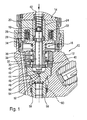
- FIG. 1 The representation according to FIG. 1 is a fuel injector according to the prior art can be seen, which is actuated by a solenoid valve and having a multi-part armature assembly.
- a fuel injector 10 as shown in FIG. 1 includes an injector body 12 in which a solenoid valve 14 is received. From the solenoid valve 14 are in the illustration according to FIG. 1 a magnetic core 20 and the magnetic core 20 enclosed by the magnetic coil 22 is shown. The solenoid 22 of the solenoid valve 14 is over in FIG. 1 not shown electrical connections energized.
- an armature assembly 16 is arranged, which comprises an armature guide 30, an anchor bolt 32 and an anchor plate 34 and is formed in several parts.
- There is an armature spring 36 which biases the anchor plate 34 against the anchor bolt 32 between the anchor plate 34 slidably mounted on the anchor bolt 32 and a lower stop on the armature guide 30.
- a closing spring 18 is located at the head of the anchor bolt 32 at.
- a dial 26 which is enclosed by a hat-shaped locking sleeve 28.
- the armature guide 30 of the armature assembly 16 as shown in FIG. 1 is attached via a clamping screw 38 in the injector body 12 of the fuel injector 10.
- a classified shim 42 Below the armature guide 30 is a classified shim 42.
- the armature guide in the injector body 12 against an injection valve member guide 58, which also received in the injector 12 of the fuel injector 10 is, biased.
- bores 40 via which flows from a control chamber 52 of the fuel injector 10 controlled amount flows to a low-pressure side return.
- the low-pressure side return is located at the in FIG. 1 illustrated embodiment according to the prior art above the closing spring 18 which is received in the through hole 24 of the magnetic core 20 of the solenoid valve 14.
- a closing element guide 44 which is a in FIG. 1 Spherical illustrated closing element 46 partially encloses.
- the here formed spherical closure member 46 is placed in its closing seat 48 and closes an outlet throttle 50 of the control chamber 52.
- the control chamber 52 is acted upon by an inlet throttle 54 under high system pressure stagnant fuel.
- the fuel under system pressure flows to the injector body 12 of the fuel injector 10 via a high-pressure port, via which the fuel injector 10 as shown in FIG FIG. 1 with a high pressure storage space of a high pressure injection system, such.
- a common-rail injection system is connected for self-igniting internal combustion engines.
- the ball-shaped closure member 46 is placed in its closing seat 48. Consequently, no control amount can flow out of the control chamber 52 of the fuel injector 10, the control chamber 52 is subjected to system pressure, so that the in FIG. 1 only partially shown, preferably needle-shaped injection valve member 56 remains in its seat, ie, injection openings formed at the combustion chamber end of the fuel injector 10 for injection of fuel into the combustion chamber of the internal combustion engine remain closed.
- the anchor plate 34 is tightened and pulls the anchor bolt 32.
- the closing element 46 is placed on the underside of the anchor bolt 32 from the closing seat 48, so that via the outlet throttle 50 fuel flows out of the control chamber 52.
- the control quantity flowing out of the control chamber 52 when the closing element 46 is open represents a liquid-air mixture, which in the embodiment according to FIG. 1 after passage of the classified shim 42 flows through the holes 40 in the armature guide 30 and the armature plate 34 flows around.
- the diverted control amount flows through a gap between the locking sleeve 28 and the magnetic core 20 to the above the closing spring 18 arranged low-pressure side return to.
- the air-liquid mixture is in contact with the underside of the armature plate 34 and acts during the closing movement of the armature assembly 16 on the armature plate 34 in the opening direction and thus influences their movement.
- this leads to scattering between the individual injections of the fuel injector 10.
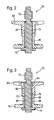
- FIG. 2 An example of an armature assembly is shown.
- an armature assembly 70 which has an anchor bolt 72 which is accommodated on the one hand in an armature guide 78, and on the other hand, an armature plate 80 is slidably received on its peripheral surface 73.
- the anchor bolt 72 of the armature assembly 70 is characterized in that it on the one hand at its the closure member 46 (see illustration according to FIG. 1 ) facing side has a radial passage 74 which merges into an axial passage 76 which is formed in an axial length 82.
- the axial length 82 of the axial channel 76 is dimensioned so that it extends from the underside of the armature guide 78 to the top of the anchor plate 80.
- the radial channel 74 and the axial channel 76 may, for. B. are designed as axial grooves on the circumference 73 of the anchor bolt 72.
- the radial passage 74 as well as through the axial passage 76 flows through the outlet throttle 50 flowing out of the control chamber 52 control amount in the interior of the armature assembly 70 as shown in FIG FIG. 2 to the low pressure side return.
- FIG. 3 shows a further example of an armature assembly 70 for use in a fuel injector.
- anchor assembly 70 is at the periphery 73 of the anchor bolt 72 also at least one axially and axially extending axial length 82 extending 76 which communicates hydraulically with a radial channel 74 at the bottom of the anchor bolt 72, so that the control amount through the interior of Armature assembly 70 can flow in the direction of the low-pressure side return.
- armature assembly 70 on the at least one axial channel 76 on the periphery 73 of the anchor bolt 72 is formed, located in the in FIG. 3 illustrated embodiment of the armature assembly 70, a further axial channel 86 within a bore 84 of the armature plate 80. Furthermore, at least one axial channel 90 extends within a bore 88 of the armature guide 78th
- a plurality of radial channels 74 are preferably formed on the underside of the anchor bolt 72. As shown in the illustration FIG. 1 As can be seen, exits the flow restrictor 50 of the control chamber 52 at the pressure relief control in a surrounding the closing element guide 44 cavity and can occur when using the inventively proposed anchor assembly 70 directly into the trained above the closing element guide 44 in the anchor bolt 72 radial channels 74.
- At least one flattening 102 is formed on the circumference 73 of an anchor bolt 100. Below the flattening is at least one bore 104, which is the lower end face of the anchor bolt 100 as shown in FIG Figure 4.1 interspersed. If the anchor bolt 100 with flattening in the context of in FIGS. 2 and 3 shown, inventively proposed anchor assembly 70 is used, then flowing when opening the closing element 46 from the control chamber 52 via the outlet throttle 50 control amount flows through the holes 104 along the at least one formed on the periphery 73 of the anchor bolt 100 flattening 102 in the direction of the head of the anchor bolt 100th and happens in FIG. 1 illustrated, horseshoe-shaped shim 26 and thus the locking sleeve 28 which is provided with openings, in the direction of the low pressure side provided return of the fuel injector 10th
- the representation according to Figure 4.2 is a view of the at least one flat 102 on the anchor bolt 100 with flattening refer. From the illustration according to Figure 4.2 shows that the holes 104 in the lower stop surface of the anchor bolt 100 can also be laterally offset from the at least one flat 102 formed.
- the in the Figures 4.1, 4.2 and 4.3 illustrated embodiment of the anchor bolt 100 with at least one flattening is characterized with respect to a simple production, in which at least one flattening 102 in the periphery 73 of the anchor bolt 100 can be performed with flattening during the machining turning of the anchor bolt 100 in the turning stage.
- at least one flattening 102 in the periphery 73 of the anchor bolt 100 can be performed with flattening during the machining turning of the anchor bolt 100 in the turning stage.
- the subsequent grinding process arise in the in Figures 4.1, 4.2 and 4.3 illustrated anchor bolt 100 with flattening little burrs, which simplifies the further processing or reworking of the anchor bolt 100 with flattening in subsequent processing steps.
- FIG. 5 shows a further example of an anchor assembly 70.
- the armature guide 78 is designed with an elongated neck 114. While the anchor bolt 72, on the circumference 73 of which at least one axial channel 76 is formed in the axial length 82, is guided inside the armature guide 78, an externally stirred anchor plate 118 on the outer circumference 116 of the extended neck 114 is the Anchor guide 78 out.
- the gap between the anchor plate 80 and the anchor bolt 72 according to the embodiment in FIG. 3 not available anymore.
- the gap between the anchor plate 80 and the outer periphery 73 of the anchor bolt 72 according to the embodiment in FIG. 3 is on the order of about 60 microns. Since this gap according to the embodiment in FIG.
- the entire amount of control flows via the at least one radial channel 54 in the lower stop of the anchor bolt 72 in the axial length 76 extending in the axial length 76 on the periphery 73 of the anchor bolt 72 and thus completely in the interior of the armature guide 78 in the direction of the low-pressure side return 62 (see Representation according to FIG. 1 ).
- FIGS. 2, 3 . 4.1, 4.2, 4.3 and 5 illustrated embodiments of the armature assembly 70 proposed according to the invention ensures that the taxed up to the control chamber 52 of the fuel injector 10 control amount through the radial channels 74 and the axial channel 76 on the periphery 73 of the anchor bolt 72 or via the axial channel 86 of the anchor plate 80, the axial channel 90 of the armature guide 78th or via which at least one flattening 102 of the anchor bolt 100 can flow off with a flattening, without influencing the movement of the anchor plate 80 or 118 by changing pressures.
- the inventively proposed execution of the armature assembly 70, the dynamics and the vibration behavior of the armature plate 80 and 118 are significantly reduced.
- the modification to the fuel injector 10 as shown in FIG. 1 essentially lies in the fact that the securing sleeve 28, which surrounds the shim 26, is to be provided with openings, so that a flow through the securing sleeve 28 is ensured by the control amount in the direction of the low-pressure side drain 62 in the fuel injector 10.
- radial channels 74 which may be formed in the lower region of the anchor bolt 72 may be replaced by radial passages extending on the underside of the anchor plate 80, or combined with these. It is irrelevant whether the anchor plate 80 at the periphery 73 of the anchor bolt 72 according to the embodiment in the FIGS. 2 and 3 is guided or whether the relative to Anchor bolt 72 movable anchor plate 118, as in the embodiment according to FIG. 5 represented, at the neck 114 of the armature guide 78 is guided.
- the training in radial channels at the bottom of the armature plate 80 and 118 offers manufacturing advantages.
Landscapes
- Engineering & Computer Science (AREA)
- Chemical & Material Sciences (AREA)
- Combustion & Propulsion (AREA)
- Mechanical Engineering (AREA)
- General Engineering & Computer Science (AREA)
- Physics & Mathematics (AREA)
- Fluid Mechanics (AREA)
- Fuel-Injection Apparatus (AREA)
Claims (3)
- Injecteur de carburant (10) avec une électrovanne (14) et un module d'induit (70), par le biais duquel un élément de fermeture (46) est actionné pour décharger en pression un espace de commande (52) et une quantité de commande s'écoulant hors de l'espace de commande (52) s'écoule dans un retour (62) du côté basse pression, le module d'induit (70) étant disposé entre le retour (62) du côté basse pression et l'élément de fermeture (46) et la quantité de commande commandée hors de l'espace de commande (52) traversant l'intérieur du module d'induit (70), le module d'induit (70) comprenant un boulon d'induit (72, 100), une plaque d'induit (80, 118) et un guide d'induit (78), dont au moins un composant présente un canal axial (76, 86, 90, 102) s'étendant dans la direction axiale, caractérisé en ce que sur la périphérie (73) du boulon d'induit (72, 100) est réalisé au moins un méplat (108, 110, 112) et le boulon d'induit (72) présente au moins un alésage (104), qui est aligné avec l'au moins un méplat (108, 110, 112) sur la périphérie (73) du boulon d'induit (100).
- Injecteur de carburant selon la revendication 1,
caractérisé en ce que le guide d'induit (78) présente au moins un canal axial intérieur (90). - Injecteur de carburant selon la revendication 1,
caractérisé en ce que le guide d'induit (78) présente un col prolongé (114), à la périphérie duquel (116) est disposée une plaque d'induit (118) guidée à l'extérieur.
Applications Claiming Priority (2)
| Application Number | Priority Date | Filing Date | Title |
|---|---|---|---|
| DE200610020691 DE102006020691A1 (de) | 2006-05-04 | 2006-05-04 | Kraftstoffinjektor mit optimiertem Rücklauf |
| PCT/EP2007/052202 WO2007128602A1 (fr) | 2006-05-04 | 2007-03-09 | injecteur de carburant avec un circuit de reflux optimisé |
Publications (2)
| Publication Number | Publication Date |
|---|---|
| EP2016276A1 EP2016276A1 (fr) | 2009-01-21 |
| EP2016276B1 true EP2016276B1 (fr) | 2010-05-26 |
Family
ID=38137443
Family Applications (1)
| Application Number | Title | Priority Date | Filing Date |
|---|---|---|---|
| EP07726725A Not-in-force EP2016276B1 (fr) | 2006-05-04 | 2007-03-09 | Injecteur de carburant avec un circuit de reflux optimise |
Country Status (3)
| Country | Link |
|---|---|
| EP (1) | EP2016276B1 (fr) |
| DE (2) | DE102006020691A1 (fr) |
| WO (1) | WO2007128602A1 (fr) |
Families Citing this family (1)
| Publication number | Priority date | Publication date | Assignee | Title |
|---|---|---|---|---|
| WO2026083194A1 (fr) * | 2024-10-16 | 2026-04-23 | ロベルト•ボッシュ•ゲゼルシャフト•ミト•ベシュレンクテル•ハフツング | Dispositif d'injection de combustible |
Family Cites Families (4)
| Publication number | Priority date | Publication date | Assignee | Title |
|---|---|---|---|---|
| GB9508623D0 (en) * | 1995-04-28 | 1995-06-14 | Lucas Ind Plc | "Fuel injection nozzle" |
| DE19650865A1 (de) * | 1996-12-07 | 1998-06-10 | Bosch Gmbh Robert | Magnetventil |
| DE19832826C2 (de) * | 1998-07-21 | 2000-08-17 | Bosch Gmbh Robert | Montageverfahren für Kraftstoff-Einspritzventil und Vorsteuerventil sowie Kraftstoff-Einspritzventil |
| EP1612403B1 (fr) * | 2004-06-30 | 2007-01-10 | C.R.F. Società Consortile per Azioni | Soupape servo pour controller l'injecteur d'un moteur à combustion interne |
-
2006
- 2006-05-04 DE DE200610020691 patent/DE102006020691A1/de not_active Withdrawn
-
2007
- 2007-03-09 EP EP07726725A patent/EP2016276B1/fr not_active Not-in-force
- 2007-03-09 WO PCT/EP2007/052202 patent/WO2007128602A1/fr not_active Ceased
- 2007-03-09 DE DE502007003946T patent/DE502007003946D1/de active Active
Also Published As
| Publication number | Publication date |
|---|---|
| DE102006020691A1 (de) | 2007-11-08 |
| DE502007003946D1 (de) | 2010-07-08 |
| WO2007128602A1 (fr) | 2007-11-15 |
| EP2016276A1 (fr) | 2009-01-21 |
Similar Documents
| Publication | Publication Date | Title |
|---|---|---|
| EP2021618B1 (fr) | Injecteur de carburant comportant une soupape de commande à compensation de pression | |
| EP2235354B1 (fr) | Injecteur de carburant dont l'élément soupape de commande présente une zone d'appui | |
| EP1831537B1 (fr) | Injecteur de systeme d'injection de carburant d'un moteur a combustion interne | |
| EP3655641B1 (fr) | Injecteur pour l'injection de carburant | |
| EP1656498A1 (fr) | Soupape d'injection de carburant commandee par une soupape pilote | |
| EP0976924B1 (fr) | Injecteur avec une servovalve | |
| EP2078157B1 (fr) | Injecteur de carburant comprenant une plaque d'étranglement et une vanne magnétique | |
| EP2235355B1 (fr) | Injecteur de carburant | |
| EP1774166B1 (fr) | Dispositif pour injecter du carburant dans la chambre de combustion d'un moteur a combustion interne | |
| EP2816219B1 (fr) | Soupape de contrôle pour un injecteur de carburant | |
| EP2276922B1 (fr) | Injecteur de carburant avec electrovanne | |
| EP2123898B1 (fr) | Injecteur de carburant | |
| EP2016276B1 (fr) | Injecteur de carburant avec un circuit de reflux optimise | |
| EP3380715B1 (fr) | Injecteur de carburant | |
| EP3060789B1 (fr) | Injecteur de carburant | |
| EP2643619B1 (fr) | Soupape comportant un élément mobile cylindrique au moins par tronçons | |
| DE102009026564A1 (de) | Kraftstoff-Injektor mit druckausgeglichenem Steuerventil | |
| EP2156044B1 (fr) | Injecteur comprenant une soupape de commande à compensation de pression | |
| WO2018028865A1 (fr) | Soupape d'aspiration à actionnement électromagnétique et pompe à carburant haute pression | |
| WO2017089011A1 (fr) | Injecteur de carburant | |
| EP3365551B1 (fr) | Soupape d'admission à commande électromagnétique et pompe haute pression munie d'une soupape d'admission | |
| WO2008125537A1 (fr) | Injecteur | |
| EP1179675A2 (fr) | Electrovanne pour commande d'un injecteur de moteurs à combustion interne et électro-aimant pour celle-ci | |
| DE102019215119A1 (de) | Kraftstoffinjektor | |
| EP4077908B1 (fr) | Buse d'injection pour l'injection de carburant sous haute pression |
Legal Events
| Date | Code | Title | Description |
|---|---|---|---|
| PUAI | Public reference made under article 153(3) epc to a published international application that has entered the european phase |
Free format text: ORIGINAL CODE: 0009012 |
|
| 17P | Request for examination filed |
Effective date: 20081204 |
|
| AK | Designated contracting states |
Kind code of ref document: A1 Designated state(s): AT BE BG CH CY CZ DE DK EE ES FI FR GB GR HU IE IS IT LI LT LU LV MC MT NL PL PT RO SE SI SK TR |
|
| AX | Request for extension of the european patent |
Extension state: AL BA HR MK RS |
|
| 17Q | First examination report despatched |
Effective date: 20090416 |
|
| DAX | Request for extension of the european patent (deleted) | ||
| RBV | Designated contracting states (corrected) |
Designated state(s): DE FR IT |
|
| GRAP | Despatch of communication of intention to grant a patent |
Free format text: ORIGINAL CODE: EPIDOSNIGR1 |
|
| GRAS | Grant fee paid |
Free format text: ORIGINAL CODE: EPIDOSNIGR3 |
|
| GRAA | (expected) grant |
Free format text: ORIGINAL CODE: 0009210 |
|
| AK | Designated contracting states |
Kind code of ref document: B1 Designated state(s): DE FR IT |
|
| REF | Corresponds to: |
Ref document number: 502007003946 Country of ref document: DE Date of ref document: 20100708 Kind code of ref document: P |
|
| PG25 | Lapsed in a contracting state [announced via postgrant information from national office to epo] |
Ref country code: IT Free format text: LAPSE BECAUSE OF FAILURE TO SUBMIT A TRANSLATION OF THE DESCRIPTION OR TO PAY THE FEE WITHIN THE PRESCRIBED TIME-LIMIT Effective date: 20100526 |
|
| PLBE | No opposition filed within time limit |
Free format text: ORIGINAL CODE: 0009261 |
|
| STAA | Information on the status of an ep patent application or granted ep patent |
Free format text: STATUS: NO OPPOSITION FILED WITHIN TIME LIMIT |
|
| 26N | No opposition filed |
Effective date: 20110301 |
|
| REG | Reference to a national code |
Ref country code: DE Ref legal event code: R097 Ref document number: 502007003946 Country of ref document: DE Effective date: 20110228 |
|
| REG | Reference to a national code |
Ref country code: FR Ref legal event code: PLFP Year of fee payment: 10 |
|
| PGFP | Annual fee paid to national office [announced via postgrant information from national office to epo] |
Ref country code: FR Payment date: 20160322 Year of fee payment: 10 |
|
| REG | Reference to a national code |
Ref country code: FR Ref legal event code: ST Effective date: 20171130 |
|
| PG25 | Lapsed in a contracting state [announced via postgrant information from national office to epo] |
Ref country code: FR Free format text: LAPSE BECAUSE OF NON-PAYMENT OF DUE FEES Effective date: 20170331 |
|
| PGFP | Annual fee paid to national office [announced via postgrant information from national office to epo] |
Ref country code: DE Payment date: 20190520 Year of fee payment: 13 |
|
| REG | Reference to a national code |
Ref country code: DE Ref legal event code: R119 Ref document number: 502007003946 Country of ref document: DE |
|
| PG25 | Lapsed in a contracting state [announced via postgrant information from national office to epo] |
Ref country code: DE Free format text: LAPSE BECAUSE OF NON-PAYMENT OF DUE FEES Effective date: 20201001 |