EP2016350B1 - Kühlvorrichtung und steuerverfahren - Google Patents
Kühlvorrichtung und steuerverfahren Download PDFInfo
- Publication number
- EP2016350B1 EP2016350B1 EP07728968A EP07728968A EP2016350B1 EP 2016350 B1 EP2016350 B1 EP 2016350B1 EP 07728968 A EP07728968 A EP 07728968A EP 07728968 A EP07728968 A EP 07728968A EP 2016350 B1 EP2016350 B1 EP 2016350B1
- Authority
- EP
- European Patent Office
- Prior art keywords
- oil
- compressor
- speed
- crpm
- mleft
- Prior art date
- Legal status (The legal status is an assumption and is not a legal conclusion. Google has not performed a legal analysis and makes no representation as to the accuracy of the status listed.)
- Not-in-force
Links
- 238000001816 cooling Methods 0.000 title claims abstract description 84
- 238000000034 method Methods 0.000 title claims description 15
- 239000012530 fluid Substances 0.000 claims description 13
- 239000003507 refrigerant Substances 0.000 claims description 10
- 230000003247 decreasing effect Effects 0.000 claims description 7
- 230000007423 decrease Effects 0.000 description 4
- 230000002411 adverse Effects 0.000 description 2
- 238000009825 accumulation Methods 0.000 description 1
- 238000005461 lubrication Methods 0.000 description 1
- 230000035699 permeability Effects 0.000 description 1
- 230000002035 prolonged effect Effects 0.000 description 1
Images

Classifications
-
- F—MECHANICAL ENGINEERING; LIGHTING; HEATING; WEAPONS; BLASTING
- F25—REFRIGERATION OR COOLING; COMBINED HEATING AND REFRIGERATION SYSTEMS; HEAT PUMP SYSTEMS; MANUFACTURE OR STORAGE OF ICE; LIQUEFACTION SOLIDIFICATION OF GASES
- F25B—REFRIGERATION MACHINES, PLANTS OR SYSTEMS; COMBINED HEATING AND REFRIGERATION SYSTEMS; HEAT PUMP SYSTEMS
- F25B31/00—Compressor arrangements
- F25B31/002—Lubrication
- F25B31/004—Lubrication oil recirculating arrangements
-
- F—MECHANICAL ENGINEERING; LIGHTING; HEATING; WEAPONS; BLASTING
- F25—REFRIGERATION OR COOLING; COMBINED HEATING AND REFRIGERATION SYSTEMS; HEAT PUMP SYSTEMS; MANUFACTURE OR STORAGE OF ICE; LIQUEFACTION SOLIDIFICATION OF GASES
- F25B—REFRIGERATION MACHINES, PLANTS OR SYSTEMS; COMBINED HEATING AND REFRIGERATION SYSTEMS; HEAT PUMP SYSTEMS
- F25B49/00—Arrangement or mounting of control or safety devices
- F25B49/02—Arrangement or mounting of control or safety devices for compression type machines, plants or systems
- F25B49/025—Motor control arrangements
-
- F—MECHANICAL ENGINEERING; LIGHTING; HEATING; WEAPONS; BLASTING
- F25—REFRIGERATION OR COOLING; COMBINED HEATING AND REFRIGERATION SYSTEMS; HEAT PUMP SYSTEMS; MANUFACTURE OR STORAGE OF ICE; LIQUEFACTION SOLIDIFICATION OF GASES
- F25B—REFRIGERATION MACHINES, PLANTS OR SYSTEMS; COMBINED HEATING AND REFRIGERATION SYSTEMS; HEAT PUMP SYSTEMS
- F25B2500/00—Problems to be solved
- F25B2500/16—Lubrication
-
- F—MECHANICAL ENGINEERING; LIGHTING; HEATING; WEAPONS; BLASTING
- F25—REFRIGERATION OR COOLING; COMBINED HEATING AND REFRIGERATION SYSTEMS; HEAT PUMP SYSTEMS; MANUFACTURE OR STORAGE OF ICE; LIQUEFACTION SOLIDIFICATION OF GASES
- F25B—REFRIGERATION MACHINES, PLANTS OR SYSTEMS; COMBINED HEATING AND REFRIGERATION SYSTEMS; HEAT PUMP SYSTEMS
- F25B2600/00—Control issues
- F25B2600/02—Compressor control
- F25B2600/025—Compressor control by controlling speed
- F25B2600/0253—Compressor control by controlling speed with variable speed
-
- Y—GENERAL TAGGING OF NEW TECHNOLOGICAL DEVELOPMENTS; GENERAL TAGGING OF CROSS-SECTIONAL TECHNOLOGIES SPANNING OVER SEVERAL SECTIONS OF THE IPC; TECHNICAL SUBJECTS COVERED BY FORMER USPC CROSS-REFERENCE ART COLLECTIONS [XRACs] AND DIGESTS
- Y02—TECHNOLOGIES OR APPLICATIONS FOR MITIGATION OR ADAPTATION AGAINST CLIMATE CHANGE
- Y02B—CLIMATE CHANGE MITIGATION TECHNOLOGIES RELATED TO BUILDINGS, e.g. HOUSING, HOUSE APPLIANCES OR RELATED END-USER APPLICATIONS
- Y02B30/00—Energy efficient heating, ventilation or air conditioning [HVAC]
- Y02B30/70—Efficient control or regulation technologies, e.g. for control of refrigerant flow, motor or heating
Definitions
- the present invention relates to a cooling device that is controlled according to the amount of oil which mixes into the cooling cycle from the compressor.
- the refrigerant fluid is circulated in the cooling cycle of the cooling devices.
- This fluid is activated through being compressed by means of a compressor.
- a certain amount of oil is present in the compressor in order to protect the movable components in the compressor against high temperature and wearing out.
- Some amount of the oil reaching the cylinder through the muffler during the operation of the compressor mixes with the refrigerant fluid and leaks into the cooling cycle.
- the oil of the compressor decreases and respectively the performance thereof is reduced.
- the oil that mixes into the cycle collects in the condenser and evaporator decreasing the efficiency of these components.
- JP-A-2000 002 468 discloses a cooling device according to the preamble of claim 1.
- the object of the present invention is to design a cooling device and control method thereof wherein the cooling performance is enhanced by controlling the flow rate of the oil that mixes into the cooling cycle from the compressor.
- the flow rate and/or amount of the oil mixing into the cooling cycle together with the fluid is controlled by means of an oil sensor disposed at the outlet of the compressor and the rotational speed of the compressor is controlled according to the measured value.
- the amount of oil mixed into the cooling cycle goes above a critical value wherein the performance of the elements in the cooling cycle starts to fall, the rotation of the compressor is started to be decreased incrementally.
- the momentary speed of the compressor is decided by a cooling algorithm that functions according to data received from a thermostat within the body.
- this cooling algorithm is suspended and the compressor rotation is determined by an algorithm that takes into account the oil flow rate information as the data.
- This algorithm starts to reduce the compressor rotation step by step when the flow rate of oil leaving the compressor starts to increase in order to prevent oil flow into the evaporator and the condenser that will affect their performance adversely.
- the time duration of the compressor operation is not desired to be prolonged too much, the flow rate of oil mixing in the cooling cycle is monitored continuously between these steps, and when it is detected to be below the critical value, the normal cooling algorithm is again activated.
- the speed is not decreased any further.
- the oil is cooled by a cooling means to increase viscosity and thus to decrease the fluency in order to decrease the flow rate of oil from the compressor mixing with the cooling cycle.
- the cooling means is a fan disposed outside preferably under the compressor.
- one oil sensor is disposed at both the inlet and the outlet of the compressor to measure the inflow and outflow rates of the oil.
- the oil outflow rate is used and the compressor speed is controlled by means of the above mentioned algorithm that controls the oil.
- another algorithm functioning simultaneously aimed at preventing damage to the compressor, calculates how much oil is left in the compressor at a certain moment by using the outflow and inflow oil rate information.
- the oil left in the compressor is nearing an amount that can harm the components of the compressor, it is operated at a rotation just below the limit speed value determined by the producer. If this precaution is not sufficient for securing the critical oil level in the compressor, then the compressor is shut down.
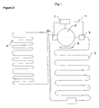
- Figure 1 is the schematic view of a cooling cycle.
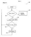
- Figure 2 is the flow chart of the control method.
- Figure 3 is the schematic view of another embodiment of the cooling cycle.
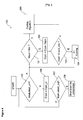
- Figure 4 is the flow chart of the control method in another embodiment.
- the cooling device (1) comprises a compressor (2) for compressing the refrigerant fluid, one or more evaporators (4) providing the ambient heat thereof to be transferred to the refrigerant fluid, a condenser (3) that condenses the refrigerant fluid and a control unit (7) that controls the cooling parameters.
- a variable speed compressor (2) is utilized in the cooling device (1).
- the cooling device (1) operates according to a cooling algorithm recorded in the control unit (7). This algorithm determines the momentary speed of the compressor (2) (Crpm) according to the thermal load inside the cooling device (1).
- the cooling device (1) of the present invention furthermore comprises an oil sensor (5) disposed at the outlet of the compressor (2) ( Figure 1 ).
- the oil sensor (5) in parallel with the normal operation of the control unit (7), measures the flow rate (Mout) of oil leaving the compressor (2) together with the refrigerant fluid and mixing in the cooling cycle at intervals determined by the producer.
- the oil sensor (5) can measure the outflow rate (Mout) of oil by making use of, for example the changes in light permeability and refraction amount of the fluid flowing in front thereof.
- the control unit (7) switches off the cooling algorithm and switches on the algorithm wherein the compressor (2) speed (rotation) is controlled depending on the flow rate (Mout) of oil.
- the control unit (7) reduces the momentary speed (Crpm) of the compressor (2) to a speed (Drpm) predetermined by the producer. Consequently, accumulation of too much oil in the evaporator (4) and the condenser (3) is tried to be forestalled ( Figure 2 ).
- the producer predetermines the limit oil flow rates (Mcr), that correspond to these speed values (Crpm) by experimental, analytical or numerical methods and records in the control unit (7). Accordingly, a different limit oil flow rate (Mcr) is used for each momentary speed (Crpm) of the compressor (2).
- the outflow rate (Mout) of oil mixing in the cooling cycle is measured again to control whether or not it has fallen below the limit value (Mcr). If the outflow rate (Mout) of oil reaches a value under the limit (Mout ⁇ Mcr), then the speed (Crpm) is not further reduced since oil outflow is sufficiently decreased, and the control unit (7) switches from oil control algorithm to normal cooling algorithm. However, if the outflow rate (Mout) of oil is not below the limit value (Mcr), the rotation reducing process should be repeated. Rotation reducing process is continued until a limit speed value (Crpm_min) determined by the producer is reached.
- Crpm_min limit speed value
- This limit value (Crpm_min) is a value smaller than the momentary compressor (2) speed (Crpm) determined by the cooling algorithm and is variable with respect to the momentary speeds (Crpm).
- the cooling device (1) can still perform the cooling function at this speed (Crpm_min); however, the compressor (2) has to be operated for a longer period of time.
- the cooling device (1) comprises a cooling means (6). Cooling of the oil is continued until the outflow rate of oil (Mout) rises above the critical level (Mcr) ( Figure 1 and Figure 2 ).
- a fan is used as the cooling means (6), preferably situated outside of the compressor (2) that provides to cool the oil ( Figure 1 ). Since the oil collects at the base of the compressor (2), this cooling means (6) is preferably situated under the compressor (2) and blows air towards the base thereof. Accordingly, the air from the fan reaches directly to the portion containing the oil. Consequently, oil is cooled rapidly increasing the viscosity. Since oil with high viscosity has reduced fluency, a lesser amount of oil starts to be mixed from the compressor (2) to the cooling cycle.
- both the oil outflow (Mout) and the inflow (Min) rates are measured by means of arranging oil sensors (5, 50), one each at the inlet and outlet of the compressor (2) ( Figure 3 ).
- the control unit (7) can calculate the amount of oil in the compressor (2) at a certain moment by means of an algorithm that protects the compressor (2) and also functions in parallel with the oil controlling algorithm, by making use of the information of the amount of oil in the compressor (2) at the start together with the amounts of total inflow and outflow of oil for a certain period of time calculated from the data received from the oil sensors (5, 50).
- control unit (7) of the cooling device (1) of the present invention functions according to the below method (100) ( Figure 2 ) comprising the steps of:
Landscapes
- Engineering & Computer Science (AREA)
- Physics & Mathematics (AREA)
- Mechanical Engineering (AREA)
- Thermal Sciences (AREA)
- General Engineering & Computer Science (AREA)
- Control Of Positive-Displacement Pumps (AREA)
- Sampling And Sample Adjustment (AREA)
- Devices That Are Associated With Refrigeration Equipment (AREA)
- Heating, Cooling, Or Curing Plastics Or The Like In General (AREA)
- Electrical Discharge Machining, Electrochemical Machining, And Combined Machining (AREA)
- Control Of Positive-Displacement Air Blowers (AREA)
- Air Conditioning Control Device (AREA)
Claims (9)
- Kühlvorrichtung (1), Folgendes umfassend: einen Kompressor (2) zum Verdichten des Kühlfluids, einen oder mehrere Verdampfer (4), die dazu dienen, ihre Umgebungswärme an das Kühlfluid zu übertragen, einen Kondensator (3), der das Kühlfluid kondensiert, und eine Steuerungseinheit (7), die die Momentandrehzahl des Kompressors (2) in Bezug auf die Wärmelast bestimmt, und die Kühlparameter steuert, und einen Ölsensor (5), dadurch gekennzeichnet, dass der Ölsensor (5) am Auslass des Kompressors (2) angeordnet ist und die Auslaufrate (Mout) von Öl misst, das sich im Kühlzyklus mit dem Kühlfluid vom Kompressor (2) vermischt, und dass die Steuerungseinheit (7) die Momentandrehzahl (Crpm) des Kompressors (2) um eine Größe (Drpm) reduziert, die vom Hersteller im Voraus festgelegt wird, wenn die Auslaufrate des Öls (Mout), die vom Ölsensor (5) gemessen wird, im Vergleich zur Momentandrehzahl (Crpm) des Kompressors (2) einen Grenzwert (Mcr) überschreitet, der vom Hersteller festgelegt wird.
- Kühlvorrichtung nach Anspruch 1, dadurch gekennzeichnet, dass die Steuerungseinheit (7) kontrolliert, ob die Auslaufrate (Mout) des Öls, das sich im Kühlzyklus vermischt, nach einer jeweiligen Reduzierung der Drehzahl unter dem Grenzwert (Mcr) liegt oder nicht, und ob ein Wert unter dem Grenzwert erreicht wird (Mout<Mcr), woraufhin sie die Reduzierung der Drehzahl unterbricht, da die Menge des auslaufenden Öls ausreichend reduziert wurde, und den normalen Kühlalgorithmus aktiviert, und die, falls die Auslaufrate (Mout) des Öls nicht unter dem Grenzwert (Mcr) liegt, eine weitere Reduzierung vornimmt.
- Kühlvorrichtung (1) nach den Ansprüchen 1 und 2, dadurch gekennzeichnet, dass die Steuerungseinheit (7) fortfährt, die Drehzahl zu reduzieren, bis ein Grenzwert (Crpm_min) erreicht wird, der vom Hersteller im Voraus festgelegt wird.
- Kühlvorrichtung (1) nach den Ansprüchen 1, 2 und 3, gekennzeichnet durch ein Kühlmittel (6), das dazu dient, das Öl zu kühlen, indem es die Drehzahl am Minimalwert (Crpm_min) konstant hält, um den Auslauf von Öl aus dem Kompressor (2) zu reduzieren.
- Kühlvorrichtung (1) nach Anspruch 4, dadurch gekennzeichnet, dass das Kühlmittel (6) ein Gebläse ist, das unter dem Kompressor (2) angeordnet ist und Luft zu dessen Basis bläst.
- Kühlvorrichtung (1) nach einem der vorangehenden Ansprüche, gekennzeichnet durch einen zweiten Ölsensor (50), der am Einlass des Kompressors (2) angeordnet ist, wobei die Steuerungseinheit (7) anhand der Daten, die sie von den beiden Ölsensoren (5, 50) empfängt, die Menge an Öl berechnen kann, die zu einem bestimmten Zeitpunkt im Kompressor (2) verblieben ist, wobei, wenn die Menge an verbliebenem Öl (Mleft) einen Schwellenwert (Mleft_cr1) erreicht, der vom Hersteller im Voraus festgelegt wird, bei dem der Kompressor (2) beschädigt werden kann, der Kompressor (2) mit einer Drehzahl (Crpm_cr) betrieben wird, die vom Hersteller im Voraus festgelegt wird und die knapp unterhalb der Grenzdrehzahl (Crpm_min) liegt.
- Kühlvorrichtung (1) nach Anspruch 6, dadurch gekennzeichnet, dass die Steuerungseinheit (7) den Kompressor (2) ausschaltet, wenn die Menge an Öl im Kompressor (2) weiter reduziert wird und einen zweiten Schwellenwert (Mleft_cr2) erreicht, der vom Hersteller im Voraus festgelegt wird.
- Steuerungsverfahren (100) für eine Kühlvorrichtung (1) nach einem der vorangehenden Ansprüche, gekennzeichnet durch folgende Schritte:- Kontrollieren, ob die Auslaufrate an Öl (Mout) aus dem Kompressor (2), das sich in den Kühlzyklus mischt, über einem bestimmten Grenzwert (Mcr) liegt (101), und falls die Auslaufrate an Öl (Mout) aus dem Kompressor (2), das sich in den Kühlzyklus mischt, unter dem Schwellenwert (Mcr) liegt, Aktivieren des Kühlalgorithmus (200),- falls sie über dem Grenzwert (Mcr) liegt, Reduzieren der Momentandrehzahl (Crpm) des Kompressors (2) um eine Größe (Drpm), die vom Hersteller im Voraus festgelegt wird (102),- Vergleichen der Drehzahl des Kompressors (2) (Crpm) mit dem Drehzahlgrenzwert (Crpm_min), der im Voraus vom Hersteller festgelegt wird (103),- falls die Drehzahl (Crpm) den Drehzahlgrenzwert (Crpm_min) erreicht hat, der vom Hersteller im Voraus festgelegt wird, Kühlen des Öls (104) und anschließend Zurückkehren zum Schritt des Kontrollierens der Ölauslaufrate (Mout) (101) und,- wenn die Drehzahl (Crpm) nicht den Drehzahlgrenzwert (Crpm_min) erreicht hat, Zurückkehren zum Schritt des Kontrollierens der Ölauslaufrate (Mout) (101).
- Steuerungsverfahren (100) nach Anspruch 8, gekennzeichnet durch folgende Schritte:- Vor dem Schritt des Kontrollierens der Ölauslaufrate (Mout) (101), Berechnen der Menge an verbliebenem Öl (Mleft) im Kompressor (2) und Vergleichen derselben mit einem Schwellenwert (Mleft_cr1), der vom Hersteller im Voraus festgelegt wird (105),- wenn die Menge an verbliebenem Öl (Mleft) den Schwellenwert (Mleft_cr1) nicht erreicht, Übergehen zum Schritt des Kontrollierens der Ölauslaufrate (Mout) (101),- wenn die Menge an verbliebenem Öl (Mleft) den Schwellenwert (Mleft_cr1) erreicht hat (105), Betreiben des Kompressors (2) bei einer Drehzahl (Crpm_cr), die unter dem Drehzahlgrenzwert (Crpm_min) liegt, der vom Kühlalgorithmus festgelegt wird (106),- Kontrollieren, ob die Menge an verbliebenem Öl (Mleft) im Kompressor (2) einen zweiten Schwellenwert (Mleft_cr2) erreicht hat, der vom Hersteller im Voraus festgelegt wird (107),- wenn die Menge an verbliebenem Öl (Mleft) sich dem kritischen Pegel (Mleft_cr) annähert (107), Ausschalten des Kompressors (2) (108) und,- wenn die Menge an verbliebenem Öl (Mleft) den zweiten Schwellenwert (Mleft_cr2) nicht erreicht hat, Zurückkehren zu dem Schritt des Vergleichens mit dem ersten Schwellenwert (Mleft_cr1) (105).
Priority Applications (1)
| Application Number | Priority Date | Filing Date | Title |
|---|---|---|---|
| SI200730051T SI2016350T1 (sl) | 2006-05-11 | 2007-05-10 | Hladilna naprava in postopek za nadzor |
Applications Claiming Priority (2)
| Application Number | Priority Date | Filing Date | Title |
|---|---|---|---|
| TR200602323 | 2006-05-11 | ||
| PCT/EP2007/054516 WO2007131931A1 (en) | 2006-05-11 | 2007-05-10 | A cooling device and the control method |
Publications (2)
| Publication Number | Publication Date |
|---|---|
| EP2016350A1 EP2016350A1 (de) | 2009-01-21 |
| EP2016350B1 true EP2016350B1 (de) | 2009-06-24 |
Family
ID=38266639
Family Applications (1)
| Application Number | Title | Priority Date | Filing Date |
|---|---|---|---|
| EP07728968A Not-in-force EP2016350B1 (de) | 2006-05-11 | 2007-05-10 | Kühlvorrichtung und steuerverfahren |
Country Status (8)
| Country | Link |
|---|---|
| EP (1) | EP2016350B1 (de) |
| CN (1) | CN101443606B (de) |
| AT (1) | ATE434746T1 (de) |
| BR (1) | BRPI0712085A2 (de) |
| DE (1) | DE602007001396D1 (de) |
| DK (1) | DK2016350T3 (de) |
| SI (1) | SI2016350T1 (de) |
| WO (1) | WO2007131931A1 (de) |
Cited By (1)
| Publication number | Priority date | Publication date | Assignee | Title |
|---|---|---|---|---|
| DE102019125070A1 (de) * | 2019-09-18 | 2021-03-18 | Ford Global Technologies, Llc | Verfahren zur Steuerung eines Kältekreislaufs, Kältekreislauf, Wärmemanagementsystem und Fahrzeug |
Family Cites Families (7)
| Publication number | Priority date | Publication date | Assignee | Title |
|---|---|---|---|---|
| US5067326A (en) * | 1979-07-31 | 1991-11-26 | Alsenz Richard H | Method and apparatus for controlling capacity of a multiple-stage cooling system |
| US5396784A (en) * | 1994-04-06 | 1995-03-14 | Carrier Corporation | Oil management system for screw compressor utilized in refrigeration system |
| JP3640749B2 (ja) * | 1996-12-19 | 2005-04-20 | シャープ株式会社 | 空気調和装置の冷凍サイクル |
| JP2000002468A (ja) * | 1998-06-16 | 2000-01-07 | Matsushita Electric Ind Co Ltd | 冷凍サイクルの潤滑油制御装置 |
| CN1183366C (zh) * | 2001-06-15 | 2005-01-05 | 广东科龙电器股份有限公司 | 制冷系统的回油控制方法 |
| JP2003166764A (ja) * | 2001-09-20 | 2003-06-13 | Denso Corp | 冷凍サイクル装置 |
| CN1745282B (zh) * | 2002-12-09 | 2010-04-21 | 哈德逊技术公司 | 用于优化致冷系统的方法和设备 |
-
2007
- 2007-05-10 EP EP07728968A patent/EP2016350B1/de not_active Not-in-force
- 2007-05-10 WO PCT/EP2007/054516 patent/WO2007131931A1/en not_active Ceased
- 2007-05-10 DK DK07728968T patent/DK2016350T3/da active
- 2007-05-10 CN CN2007800168208A patent/CN101443606B/zh not_active Expired - Fee Related
- 2007-05-10 DE DE602007001396T patent/DE602007001396D1/de not_active Expired - Fee Related
- 2007-05-10 SI SI200730051T patent/SI2016350T1/sl unknown
- 2007-05-10 AT AT07728968T patent/ATE434746T1/de not_active IP Right Cessation
- 2007-05-10 BR BRPI0712085-0A patent/BRPI0712085A2/pt not_active IP Right Cessation
Cited By (2)
| Publication number | Priority date | Publication date | Assignee | Title |
|---|---|---|---|---|
| DE102019125070A1 (de) * | 2019-09-18 | 2021-03-18 | Ford Global Technologies, Llc | Verfahren zur Steuerung eines Kältekreislaufs, Kältekreislauf, Wärmemanagementsystem und Fahrzeug |
| DE102019125070B4 (de) | 2019-09-18 | 2022-10-06 | Ford Global Technologies, Llc | Verfahren zur Steuerung eines Kältekreislaufs, Kältekreislauf, Wärmemanagementsystem und Fahrzeug |
Also Published As
| Publication number | Publication date |
|---|---|
| WO2007131931A1 (en) | 2007-11-22 |
| CN101443606A (zh) | 2009-05-27 |
| BRPI0712085A2 (pt) | 2012-02-14 |
| EP2016350A1 (de) | 2009-01-21 |
| CN101443606B (zh) | 2012-06-20 |
| DE602007001396D1 (de) | 2009-08-06 |
| DK2016350T3 (da) | 2009-11-02 |
| ATE434746T1 (de) | 2009-07-15 |
| SI2016350T1 (sl) | 2009-12-31 |
Similar Documents
| Publication | Publication Date | Title |
|---|---|---|
| JP6374572B2 (ja) | 可変速圧縮機を有する冷却システム | |
| EP1379817B1 (de) | Verfahren und vorrichtung zur steuerung des abziehens von wärme aus dem kondensator in einem kühlsystem | |
| JP5506770B2 (ja) | 空気調和機 | |
| JP2008267787A5 (de) | ||
| JP2008267787A (ja) | 冷凍装置 | |
| JP5318057B2 (ja) | 冷凍機、冷凍装置及び空気調和装置 | |
| CN105465970A (zh) | 空调系统油堵的处理方法及处理装置、空调器 | |
| JP6177218B2 (ja) | 空気調和機 | |
| EP2016350B1 (de) | Kühlvorrichtung und steuerverfahren | |
| CN101408355A (zh) | 冷冻装置及冷冻装置的运转方法 | |
| EP3012559B1 (de) | Auswahl einer Steuerungsstrategie für ein Expansionsventil | |
| EP3059510A1 (de) | Vorrichtung und verfahren zum entfeuchten einer flüssigkeit | |
| JP4767133B2 (ja) | 冷凍サイクル装置 | |
| JP4475660B2 (ja) | 冷凍装置 | |
| JP6086236B2 (ja) | 冷凍装置の圧縮機の容量制御方法および容量制御装置 | |
| JP7066420B2 (ja) | 冷凍機の保護装置及び保護方法 | |
| KR20090070000A (ko) | 공기조화기의 과부하 방지 장치 | |
| KR20060069714A (ko) | 공기 조화기의 압축기 토출온도 상승 억제 방법 | |
| JP2008309483A (ja) | 冷凍装置 | |
| JP2006170575A (ja) | 圧縮機制御システム | |
| JP4326274B2 (ja) | 冷凍回路 | |
| KR100606267B1 (ko) | 연속 냉방 운전이 가능한 에어콘 | |
| JP2007232321A (ja) | 空気調和機 | |
| JP2025006008A (ja) | 油冷式圧縮機の冷却ファン制御方法及び油冷式圧縮機 | |
| KR100696713B1 (ko) | 에어컨의 압축기 보호 장치 및 방법 |
Legal Events
| Date | Code | Title | Description |
|---|---|---|---|
| PUAI | Public reference made under article 153(3) epc to a published international application that has entered the european phase |
Free format text: ORIGINAL CODE: 0009012 |
|
| 17P | Request for examination filed |
Effective date: 20081028 |
|
| AK | Designated contracting states |
Kind code of ref document: A1 Designated state(s): AT BE BG CH CY CZ DE DK EE ES FI FR GB GR HU IE IS IT LI LT LU LV MC MT NL PL PT RO SE SI SK TR |
|
| AX | Request for extension of the european patent |
Extension state: AL BA HR MK RS |
|
| GRAP | Despatch of communication of intention to grant a patent |
Free format text: ORIGINAL CODE: EPIDOSNIGR1 |
|
| DAX | Request for extension of the european patent (deleted) | ||
| GRAS | Grant fee paid |
Free format text: ORIGINAL CODE: EPIDOSNIGR3 |
|
| GRAA | (expected) grant |
Free format text: ORIGINAL CODE: 0009210 |
|
| AK | Designated contracting states |
Kind code of ref document: B1 Designated state(s): AT BE BG CH CY CZ DE DK EE ES FI FR GB GR HU IE IS IT LI LT LU LV MC MT NL PL PT RO SE SI SK TR |
|
| REG | Reference to a national code |
Ref country code: GB Ref legal event code: FG4D |
|
| REG | Reference to a national code |
Ref country code: CH Ref legal event code: EP |
|
| REG | Reference to a national code |
Ref country code: IE Ref legal event code: FG4D |
|
| REF | Corresponds to: |
Ref document number: 602007001396 Country of ref document: DE Date of ref document: 20090806 Kind code of ref document: P |
|
| PG25 | Lapsed in a contracting state [announced via postgrant information from national office to epo] |
Ref country code: LT Free format text: LAPSE BECAUSE OF FAILURE TO SUBMIT A TRANSLATION OF THE DESCRIPTION OR TO PAY THE FEE WITHIN THE PRESCRIBED TIME-LIMIT Effective date: 20090624 Ref country code: FI Free format text: LAPSE BECAUSE OF FAILURE TO SUBMIT A TRANSLATION OF THE DESCRIPTION OR TO PAY THE FEE WITHIN THE PRESCRIBED TIME-LIMIT Effective date: 20090624 Ref country code: AT Free format text: LAPSE BECAUSE OF FAILURE TO SUBMIT A TRANSLATION OF THE DESCRIPTION OR TO PAY THE FEE WITHIN THE PRESCRIBED TIME-LIMIT Effective date: 20090624 |
|
| REG | Reference to a national code |
Ref country code: DK Ref legal event code: T3 |
|
| PG25 | Lapsed in a contracting state [announced via postgrant information from national office to epo] |
Ref country code: SE Free format text: LAPSE BECAUSE OF FAILURE TO SUBMIT A TRANSLATION OF THE DESCRIPTION OR TO PAY THE FEE WITHIN THE PRESCRIBED TIME-LIMIT Effective date: 20090924 Ref country code: PL Free format text: LAPSE BECAUSE OF FAILURE TO SUBMIT A TRANSLATION OF THE DESCRIPTION OR TO PAY THE FEE WITHIN THE PRESCRIBED TIME-LIMIT Effective date: 20090624 Ref country code: LV Free format text: LAPSE BECAUSE OF FAILURE TO SUBMIT A TRANSLATION OF THE DESCRIPTION OR TO PAY THE FEE WITHIN THE PRESCRIBED TIME-LIMIT Effective date: 20090624 |
|
| NLV1 | Nl: lapsed or annulled due to failure to fulfill the requirements of art. 29p and 29m of the patents act | ||
| PG25 | Lapsed in a contracting state [announced via postgrant information from national office to epo] |
Ref country code: IS Free format text: LAPSE BECAUSE OF FAILURE TO SUBMIT A TRANSLATION OF THE DESCRIPTION OR TO PAY THE FEE WITHIN THE PRESCRIBED TIME-LIMIT Effective date: 20091024 Ref country code: CZ Free format text: LAPSE BECAUSE OF FAILURE TO SUBMIT A TRANSLATION OF THE DESCRIPTION OR TO PAY THE FEE WITHIN THE PRESCRIBED TIME-LIMIT Effective date: 20090624 Ref country code: EE Free format text: LAPSE BECAUSE OF FAILURE TO SUBMIT A TRANSLATION OF THE DESCRIPTION OR TO PAY THE FEE WITHIN THE PRESCRIBED TIME-LIMIT Effective date: 20090624 Ref country code: ES Free format text: LAPSE BECAUSE OF FAILURE TO SUBMIT A TRANSLATION OF THE DESCRIPTION OR TO PAY THE FEE WITHIN THE PRESCRIBED TIME-LIMIT Effective date: 20091005 |
|
| PG25 | Lapsed in a contracting state [announced via postgrant information from national office to epo] |
Ref country code: BE Free format text: LAPSE BECAUSE OF FAILURE TO SUBMIT A TRANSLATION OF THE DESCRIPTION OR TO PAY THE FEE WITHIN THE PRESCRIBED TIME-LIMIT Effective date: 20090624 Ref country code: NL Free format text: LAPSE BECAUSE OF FAILURE TO SUBMIT A TRANSLATION OF THE DESCRIPTION OR TO PAY THE FEE WITHIN THE PRESCRIBED TIME-LIMIT Effective date: 20090624 |
|
| PG25 | Lapsed in a contracting state [announced via postgrant information from national office to epo] |
Ref country code: PT Free format text: LAPSE BECAUSE OF FAILURE TO SUBMIT A TRANSLATION OF THE DESCRIPTION OR TO PAY THE FEE WITHIN THE PRESCRIBED TIME-LIMIT Effective date: 20091024 Ref country code: BG Free format text: LAPSE BECAUSE OF FAILURE TO SUBMIT A TRANSLATION OF THE DESCRIPTION OR TO PAY THE FEE WITHIN THE PRESCRIBED TIME-LIMIT Effective date: 20090924 |
|
| PLBE | No opposition filed within time limit |
Free format text: ORIGINAL CODE: 0009261 |
|
| STAA | Information on the status of an ep patent application or granted ep patent |
Free format text: STATUS: NO OPPOSITION FILED WITHIN TIME LIMIT |
|
| 26N | No opposition filed |
Effective date: 20100325 |
|
| PG25 | Lapsed in a contracting state [announced via postgrant information from national office to epo] |
Ref country code: GR Free format text: LAPSE BECAUSE OF FAILURE TO SUBMIT A TRANSLATION OF THE DESCRIPTION OR TO PAY THE FEE WITHIN THE PRESCRIBED TIME-LIMIT Effective date: 20090925 |
|
| PG25 | Lapsed in a contracting state [announced via postgrant information from national office to epo] |
Ref country code: MC Free format text: LAPSE BECAUSE OF NON-PAYMENT OF DUE FEES Effective date: 20100531 |
|
| REG | Reference to a national code |
Ref country code: FR Ref legal event code: ST Effective date: 20110131 |
|
| PG25 | Lapsed in a contracting state [announced via postgrant information from national office to epo] |
Ref country code: IT Free format text: LAPSE BECAUSE OF FAILURE TO SUBMIT A TRANSLATION OF THE DESCRIPTION OR TO PAY THE FEE WITHIN THE PRESCRIBED TIME-LIMIT Effective date: 20090624 |
|
| PG25 | Lapsed in a contracting state [announced via postgrant information from national office to epo] |
Ref country code: DE Free format text: LAPSE BECAUSE OF NON-PAYMENT OF DUE FEES Effective date: 20101201 Ref country code: IE Free format text: LAPSE BECAUSE OF NON-PAYMENT OF DUE FEES Effective date: 20100510 Ref country code: MT Free format text: LAPSE BECAUSE OF FAILURE TO SUBMIT A TRANSLATION OF THE DESCRIPTION OR TO PAY THE FEE WITHIN THE PRESCRIBED TIME-LIMIT Effective date: 20090624 |
|
| PG25 | Lapsed in a contracting state [announced via postgrant information from national office to epo] |
Ref country code: FR Free format text: LAPSE BECAUSE OF NON-PAYMENT OF DUE FEES Effective date: 20100531 |
|
| REG | Reference to a national code |
Ref country code: CH Ref legal event code: PL |
|
| GBPC | Gb: european patent ceased through non-payment of renewal fee |
Effective date: 20110510 |
|
| PG25 | Lapsed in a contracting state [announced via postgrant information from national office to epo] |
Ref country code: CH Free format text: LAPSE BECAUSE OF NON-PAYMENT OF DUE FEES Effective date: 20110531 Ref country code: LI Free format text: LAPSE BECAUSE OF NON-PAYMENT OF DUE FEES Effective date: 20110531 |
|
| PG25 | Lapsed in a contracting state [announced via postgrant information from national office to epo] |
Ref country code: GB Free format text: LAPSE BECAUSE OF NON-PAYMENT OF DUE FEES Effective date: 20110510 |
|
| PG25 | Lapsed in a contracting state [announced via postgrant information from national office to epo] |
Ref country code: CY Free format text: LAPSE BECAUSE OF FAILURE TO SUBMIT A TRANSLATION OF THE DESCRIPTION OR TO PAY THE FEE WITHIN THE PRESCRIBED TIME-LIMIT Effective date: 20090624 |
|
| PG25 | Lapsed in a contracting state [announced via postgrant information from national office to epo] |
Ref country code: LU Free format text: LAPSE BECAUSE OF NON-PAYMENT OF DUE FEES Effective date: 20100510 Ref country code: HU Free format text: LAPSE BECAUSE OF FAILURE TO SUBMIT A TRANSLATION OF THE DESCRIPTION OR TO PAY THE FEE WITHIN THE PRESCRIBED TIME-LIMIT Effective date: 20091225 |
|
| PG25 | Lapsed in a contracting state [announced via postgrant information from national office to epo] |
Ref country code: RO Free format text: LAPSE BECAUSE OF FAILURE TO SUBMIT A TRANSLATION OF THE DESCRIPTION OR TO PAY THE FEE WITHIN THE PRESCRIBED TIME-LIMIT Effective date: 20090624 |
|
| PGFP | Annual fee paid to national office [announced via postgrant information from national office to epo] |
Ref country code: SI Payment date: 20160425 Year of fee payment: 10 Ref country code: SK Payment date: 20160509 Year of fee payment: 10 Ref country code: DK Payment date: 20160519 Year of fee payment: 10 |
|
| REG | Reference to a national code |
Ref country code: DK Ref legal event code: EBP Effective date: 20170531 |
|
| PG25 | Lapsed in a contracting state [announced via postgrant information from national office to epo] |
Ref country code: SK Free format text: LAPSE BECAUSE OF NON-PAYMENT OF DUE FEES Effective date: 20170510 |
|
| REG | Reference to a national code |
Ref country code: SK Ref legal event code: MM4A Ref document number: E 5860 Country of ref document: SK Effective date: 20170510 |
|
| PG25 | Lapsed in a contracting state [announced via postgrant information from national office to epo] |
Ref country code: SI Free format text: LAPSE BECAUSE OF NON-PAYMENT OF DUE FEES Effective date: 20170511 |
|
| REG | Reference to a national code |
Ref country code: SI Ref legal event code: KO00 Effective date: 20180111 |
|
| PG25 | Lapsed in a contracting state [announced via postgrant information from national office to epo] |
Ref country code: DK Free format text: LAPSE BECAUSE OF NON-PAYMENT OF DUE FEES Effective date: 20170531 |
|
| PGFP | Annual fee paid to national office [announced via postgrant information from national office to epo] |
Ref country code: TR Payment date: 20190424 Year of fee payment: 13 |
|
| PG25 | Lapsed in a contracting state [announced via postgrant information from national office to epo] |
Ref country code: TR Free format text: LAPSE BECAUSE OF NON-PAYMENT OF DUE FEES Effective date: 20200510 |