EP2016413B1 - Erfassungsvorrichtung und -verfahren - Google Patents
Erfassungsvorrichtung und -verfahren Download PDFInfo
- Publication number
- EP2016413B1 EP2016413B1 EP07747980.6A EP07747980A EP2016413B1 EP 2016413 B1 EP2016413 B1 EP 2016413B1 EP 07747980 A EP07747980 A EP 07747980A EP 2016413 B1 EP2016413 B1 EP 2016413B1
- Authority
- EP
- European Patent Office
- Prior art keywords
- magnetic
- coil
- detection
- particle
- field
- Prior art date
- Legal status (The legal status is an assumption and is not a legal conclusion. Google has not performed a legal analysis and makes no representation as to the accuracy of the status listed.)
- Ceased
Links
- 238000001514 detection method Methods 0.000 title claims description 104
- 238000000034 method Methods 0.000 title claims description 30
- 230000005291 magnetic effect Effects 0.000 claims description 93
- 239000002245 particle Substances 0.000 claims description 93
- 230000005284 excitation Effects 0.000 claims description 61
- 238000005259 measurement Methods 0.000 claims description 47
- 230000004044 response Effects 0.000 claims description 34
- 239000006249 magnetic particle Substances 0.000 claims description 30
- 230000001419 dependent effect Effects 0.000 claims description 22
- 230000008859 change Effects 0.000 claims description 20
- 230000005415 magnetization Effects 0.000 claims description 20
- 238000009826 distribution Methods 0.000 claims description 15
- 239000012491 analyte Substances 0.000 claims description 13
- 230000008878 coupling Effects 0.000 claims description 13
- 238000010168 coupling process Methods 0.000 claims description 13
- 238000005859 coupling reaction Methods 0.000 claims description 13
- 239000012530 fluid Substances 0.000 claims description 13
- 230000007423 decrease Effects 0.000 claims description 12
- 239000000463 material Substances 0.000 claims description 11
- 230000004907 flux Effects 0.000 claims description 7
- 238000010521 absorption reaction Methods 0.000 claims description 6
- 238000002347 injection Methods 0.000 claims description 6
- 239000007924 injection Substances 0.000 claims description 6
- 230000000694 effects Effects 0.000 claims description 5
- 230000003993 interaction Effects 0.000 claims description 5
- 238000012544 monitoring process Methods 0.000 claims description 5
- 238000013208 measuring procedure Methods 0.000 claims description 4
- 230000009466 transformation Effects 0.000 claims description 4
- 238000004804 winding Methods 0.000 claims description 4
- 238000005315 distribution function Methods 0.000 claims description 3
- 230000001105 regulatory effect Effects 0.000 claims description 3
- 229920006395 saturated elastomer Polymers 0.000 claims description 3
- 238000000429 assembly Methods 0.000 claims description 2
- 230000000712 assembly Effects 0.000 claims description 2
- 239000011248 coating agent Substances 0.000 claims description 2
- 238000000576 coating method Methods 0.000 claims description 2
- 238000012986 modification Methods 0.000 claims description 2
- 230000004048 modification Effects 0.000 claims description 2
- 239000000523 sample Substances 0.000 description 56
- 230000002776 aggregation Effects 0.000 description 13
- 239000000243 solution Substances 0.000 description 12
- 238000005054 agglomeration Methods 0.000 description 8
- 230000035945 sensitivity Effects 0.000 description 7
- YBJHBAHKTGYVGT-ZKWXMUAHSA-N (+)-Biotin Chemical compound N1C(=O)N[C@@H]2[C@H](CCCCC(=O)O)SC[C@@H]21 YBJHBAHKTGYVGT-ZKWXMUAHSA-N 0.000 description 6
- 108020004414 DNA Proteins 0.000 description 5
- 238000004220 aggregation Methods 0.000 description 5
- 230000008901 benefit Effects 0.000 description 5
- 239000000427 antigen Substances 0.000 description 4
- 102000036639 antigens Human genes 0.000 description 4
- 108091007433 antigens Proteins 0.000 description 4
- 235000020958 biotin Nutrition 0.000 description 4
- 238000010408 sweeping Methods 0.000 description 4
- 108090001008 Avidin Proteins 0.000 description 3
- 229960002685 biotin Drugs 0.000 description 3
- 239000011616 biotin Substances 0.000 description 3
- 230000006698 induction Effects 0.000 description 3
- 239000007788 liquid Substances 0.000 description 3
- 108090000623 proteins and genes Proteins 0.000 description 3
- 102000004169 proteins and genes Human genes 0.000 description 3
- 239000002904 solvent Substances 0.000 description 3
- 230000005653 Brownian motion process Effects 0.000 description 2
- 108010074506 Transfer Factor Proteins 0.000 description 2
- 238000004458 analytical method Methods 0.000 description 2
- 230000015572 biosynthetic process Effects 0.000 description 2
- 238000005537 brownian motion Methods 0.000 description 2
- 238000006243 chemical reaction Methods 0.000 description 2
- 238000013461 design Methods 0.000 description 2
- 238000009792 diffusion process Methods 0.000 description 2
- 238000011835 investigation Methods 0.000 description 2
- 230000033001 locomotion Effects 0.000 description 2
- 239000002122 magnetic nanoparticle Substances 0.000 description 2
- 244000005700 microbiome Species 0.000 description 2
- 239000002105 nanoparticle Substances 0.000 description 2
- 239000002907 paramagnetic material Substances 0.000 description 2
- 230000003068 static effect Effects 0.000 description 2
- 239000000126 substance Substances 0.000 description 2
- 241000894006 Bacteria Species 0.000 description 1
- 238000005481 NMR spectroscopy Methods 0.000 description 1
- 108091028043 Nucleic acid sequence Proteins 0.000 description 1
- 241000700605 Viruses Species 0.000 description 1
- 230000004931 aggregating effect Effects 0.000 description 1
- 238000003556 assay Methods 0.000 description 1
- 150000001615 biotins Chemical class 0.000 description 1
- 239000003990 capacitor Substances 0.000 description 1
- 230000000295 complement effect Effects 0.000 description 1
- 238000010276 construction Methods 0.000 description 1
- 230000003247 decreasing effect Effects 0.000 description 1
- 238000002405 diagnostic procedure Methods 0.000 description 1
- 239000000539 dimer Substances 0.000 description 1
- 230000008034 disappearance Effects 0.000 description 1
- 238000002296 dynamic light scattering Methods 0.000 description 1
- NLQFUUYNQFMIJW-UHFFFAOYSA-N dysprosium(III) oxide Inorganic materials O=[Dy]O[Dy]=O NLQFUUYNQFMIJW-UHFFFAOYSA-N 0.000 description 1
- 239000002158 endotoxin Substances 0.000 description 1
- 238000002474 experimental method Methods 0.000 description 1
- 229920006008 lipopolysaccharide Polymers 0.000 description 1
- 230000001404 mediated effect Effects 0.000 description 1
- 239000012528 membrane Substances 0.000 description 1
- 230000003071 parasitic effect Effects 0.000 description 1
- 230000010363 phase shift Effects 0.000 description 1
- 239000000843 powder Substances 0.000 description 1
- 239000013074 reference sample Substances 0.000 description 1
- 238000004062 sedimentation Methods 0.000 description 1
- 239000007787 solid Substances 0.000 description 1
- 239000012798 spherical particle Substances 0.000 description 1
- 230000003746 surface roughness Effects 0.000 description 1
- 239000000725 suspension Substances 0.000 description 1
- 238000012360 testing method Methods 0.000 description 1
- 230000036962 time dependent Effects 0.000 description 1
Images


Classifications
-
- G—PHYSICS
- G01—MEASURING; TESTING
- G01R—MEASURING ELECTRIC VARIABLES; MEASURING MAGNETIC VARIABLES
- G01R33/00—Arrangements or instruments for measuring magnetic variables
- G01R33/12—Measuring magnetic properties of articles or specimens of solids or fluids
-
- G—PHYSICS
- G01—MEASURING; TESTING
- G01R—MEASURING ELECTRIC VARIABLES; MEASURING MAGNETIC VARIABLES
- G01R33/00—Arrangements or instruments for measuring magnetic variables
- G01R33/12—Measuring magnetic properties of articles or specimens of solids or fluids
- G01R33/1269—Measuring magnetic properties of articles or specimens of solids or fluids of molecules labeled with magnetic beads
-
- G—PHYSICS
- G01—MEASURING; TESTING
- G01R—MEASURING ELECTRIC VARIABLES; MEASURING MAGNETIC VARIABLES
- G01R33/00—Arrangements or instruments for measuring magnetic variables
- G01R33/12—Measuring magnetic properties of articles or specimens of solids or fluids
- G01R33/1276—Measuring magnetic properties of articles or specimens of solids or fluids of magnetic particles, e.g. imaging of magnetic nanoparticles
-
- G—PHYSICS
- G01—MEASURING; TESTING
- G01R—MEASURING ELECTRIC VARIABLES; MEASURING MAGNETIC VARIABLES
- G01R33/00—Arrangements or instruments for measuring magnetic variables
- G01R33/12—Measuring magnetic properties of articles or specimens of solids or fluids
- G01R33/16—Measuring susceptibility
Definitions
- Brownian relaxation of a magnetic particle system with thermally blocked magnetic single domains (in the particles) can be detected by sweeping the frequency of the measuring field and measure the magnetic response, i.e. the real and imaginary part of the magnetic response, see for example WO 03/019188 , by the same applicant.
- the characteristic Brownian relaxation frequency the real part of the magnetic response decreases and the imaginary part exhibit a maximum. From the frequency dependent magnetic response the Brownian relaxation frequency can be determined.
- This method is very sensitive since it is possible to use the sensitivity of the lock-in amplifier technique in order to detect the magnetic response from the detection coil system placed in (the centre of) an excitation coil.
- the sensitivity of this technique can be further increased by tuning the resonance of the detection coil by an external capacitor in such way that the measurement at each excitation frequency is made at the peak value of the response of the detection coils.
- this technique requires that the frequency is swept over the Brownian relaxation frequency peak. This technique is described below.
- One disadvantage of the detection in the frequency domain is that the procedure is relatively slow and requires changes of the sample position from one detection coil to another.
- One object of the present invention is to measure small magnetic signals from samples with low magnetic content or low magnetic properties. Another object of the present invention is to measure the increase of the magnetisation of the sample when the field is applied and the decrease of magnetisation when the field is turned off. Yet another object of the invention is to eliminate frequency sweep of a measuring field.
- sample response measurements according to the invention is its speed; the measurements are much faster than the previously described technique based on the sweeping of the frequency of the excitation field.
- a method for detecting changes of a magnetic response of at least one magnetic particle in a carrier fluid comprising: using a measuring procedure comprising measuring the characteristic rotation time of the magnetic particle, the measuring procedure further involving measuring Brownian relaxation in the carrier fluid under influence of an external pulsed excitation magnetic field, and based on the influence of the external pulsed excitation magnetic field measuring a hydrodynamic volume of a particle or a change in a hydrodynamic volume of the particle change upon modification of an effective volume of the particle or its interaction with the carrier fluid by detecting change of magnetisation of the particle with time by monitoring change of an output signal in a detection coil.
- the detection coil system detects a differential induced voltage which is dependent on change of a magnetic flux over a period.
- N a number of turns in two identical detection coils
- A the cross sectional area in the detection coils
- H the magnetic field produced by the excitation coil
- ⁇ a magnetic coupling factor
- M a magnetization of the particle system.
- approximation depends on magnetic particles containing a number of magnetic single domains and a total magnetic moment is a vector sum of the individual magnetic moments from each of the single domains.
- a hydrodynamic size distribution of the magnetic particle system is determined using mentioned model or any other similar models.
- the method may further comprise absorption of molecules on a surface of particles whereby the hydrodynamic radius of the particles increases, and when the surface is saturated with molecules, a hydrodynamic volume have increased by a shell that has a thickness surrounding the original particle, and that the hydrodynamic radius increase is linear to the coverage.
- r H is the initial hydrodynamic radius before the particle surface became covered with molecules.
- the particle is provided with an external layer.
- the invention also relates to a device for detecting a magnetic field response or changes in a magnetic response of at least one magnetic particle in a carrier fluid.
- the detection comprises measuring the magnetic particles characteristic rotation period, and the measurement involving measurement of a Brownian relaxation in the carrier fluid under influence of an external pulsed magnetic field.
- the device comprises means for generating the pulsed magnetic field, at least two substantially identical detection coils connected in gradiometer coupling and means for connecting to detection electronics for measuring the frequency.
- the device further comprises a detection coil system comprising a first detection coil and a second detection coil, an excitation coil and a sample holder, wherein a voltage difference is dependent on the detection coils' number of turns or physical characteristics.
- the excitation coil is wound as a solenoid with a specific length, diameter and number of turns of the winding.
- the device may further comprise extra shim coils at top and bottom of the solenoid in order to generate a more homogenous magnetic field in the excitation coil.
- the detection coil system may be arranged in a form of a first order gradiometer coupling placed in the center of the excitation coil. According to another embodiment the detection coil system is arranged as two well matched coils coupled together. The detection coil system is arranged to detect a rate of a magnetic flux difference between the two coils.
- the detection coil system is formed by positioning two matched coils with their length axis substantially parallel to a length axis of the excitation coil.
- the two detection coils have a specific length, diameter and a number of turns of the wirings and the excitation coils gives a signal strength from the detection coil system.
- the detection coils are wounded in two different directions, i.e. clockwise and counterclockwise and coupled in series or the detection coils are wounded in the same directions but coupled together so that the induced voltages in the two coils are in the opposite direction.
- a magnetic signal is measured first from a measurement with a sample in one of the coils and then another measurement of the sample in the other coil.
- a total voltage detected when the sample is in the first coil is V 1 + V background and the total voltage detected when the sample is in the second coil is - V 2 + V background , and a difference of the two measurements results in V 1+ V 2 which eliminates a background noise and the mean value of V 1 + V 2 represents a signal from the sample.
- an external pulsed magnetic field is applied over the same particle system, and a magnetization of the particles is measured in time domain either by measuring the increase of magnetisation immediately after application of a pulse or by measuring the decay of magnetisation after the pulse has been switched off.
- a pulsed magnetic field may be applied over the same particle system, and a magnetization of the particles increases when the field is applied and decrease exponentially when the field is removed; where the exponential behaviour is characteristic of relaxation time which is proportional to the inverse of the Brownian relaxation frequency.
- the frequency of a measuring field is not swept but same information is obtained by performing a Fourier transformation of the relaxation of the magnetic response in the time domain.
- the information is a frequency dependent magnetic response.
- the hydrodynamic size distribution of the magnetic particle system is determined by measuring the induced voltage, both when the field is on and when the field is switched off.
- a duty cycle of the pulse train ( a / T ) is chosen so that an exponential increase of the magnetization, when the field is on, and an exponential decay of the magnetization, when the field is switched off, is fully detected in the detection time window.
- the device may comprise a tunable capacitance coupled in parallel to a capacitance of the system and a resonant frequency of each coil is adjusted to a measuring frequency.
- the device may comprise a capillary as a sample holder and a fluidic flow system to deliver the sample to a detection area. Accordingly, the sample is injected into a flow as an assembly having a width that is determined by an injection time and speed.
- the device may further comprise means for regulating the flow so that the assembly can be stopped at a desired position, such as at a measuring position.
- the device may also have means for using several assemblies of the same or different materials created by successive injections.
- the invention also relates to a method of calibrating a previously mentioned system.
- the method comprises: a first step of measuring the system response with an empty sample holder, a second step of computing difference in signal when the empty sample holder is in the first coil to when the sample holder is in the second coil, a third step of measuring the system with a sample containing a material with a known and preferably frequency independent magnetic susceptibility; and calibrating the system based on the measurements.
- the difference is attributed to the dielectric properties of the sample holder and the mechanical arm moving the sample holder.
- the material is a paramagnetic material.
- the calibration materials are chosen to have a frequency independent susceptibility in the frequency range that is used the system.
- the value of the susceptibility of the calibration material is in the same range as for the measured sample.
- the geometry and dimensions of the calibration sample is in the same as for the measurement samples, in order to get the correct coupling factor in the detection coil.
- a detection coil system detects the differential induced voltage which is dependent on the change of the magnetic flux over a period.
- N is the number of turns in the two identical detection coils (that is forming the detection coil system described below)
- A is the cross sectional area in the detection coils
- H the magnetic field produced by the excitation coil
- ⁇ a magnetic coupling factor which depends on the geometry and dimensions of the sample with respect to the detection coil dimensions
- M is the magnetization of the particle system.
- the coupling factor ⁇ is usually determined from calibration of the induction coil system with a substance with 1) a known well defined susceptibility and 2) the same dimensions of the calibration sample as for the measured sample. This equation is the same for both an excitation field with a sinus field or a pulsed magnetic field.
- H 0 the amplitude of the magnetic field.
- ⁇ o the DC susceptibility
- w the angular frequency (2 ⁇ f)
- r H the hydrodynamic radius of the particles
- f ( r H ) is the hydrodynamic radius distribution function (where the log-normal distribution can be used)
- V H is the hydrodynamic volume
- N analyt_p N analyt ⁇ N ptot ⁇ f r H ⁇ d ⁇ r H ⁇ 4 ⁇ ⁇ ⁇ r H 2 ⁇ N ptot ⁇ f r H ⁇ 4 ⁇ ⁇ ⁇ r H 2 ⁇ dr H
- N analyt is the total number of molecules
- N ptot is the total number of particles in the liquid.
- a preferred detection coil system 100 is illustrated schematically in Fig. 1 .
- the system comprises 1 first detection coil 110 and a second detection coil 120, an excitation coil 130 and a sample holder 140.
- the detection coils have a number of (N) turns so arranged that they produce a voltage difference. Other physical characteristics, such as diameter, size etc. may also be used to produce a voltage difference.
- a current I passes through the excitation coil 130.
- the excitation coil 130 is wound as an ordinary solenoid with a specific length, diameter and number of turns of the winding.
- the excitation coil produces the excitation field, H , and have the effect on the signal response as described in eq. 1 - eq. 3.
- the number of turns of the windings per unit length of the solenoid and the current in the excitation coil produces the excitation field.
- Extra shim coils may be placed at the top and the bottom of the solenoid in order to generate a more homogenous magnetic field in the excitation coil, see for instance " Modelling the Static Fringe Field of Superconducting Magnets" by P. Jegli, et al, J.
- the detection coil system 110, 120 in a form of a first order gradiometer coupling is placed in the center of the excitation coil.
- the detection coil system can also be viewed as two well matched coils coupled together.
- the detection coil system detects the rate of the magnetic flux difference between the two coils.
- the detection coil system is formed by positioning two well matched coils with their length axis (substantially) parallel to the length axis of the excitation coil.
- the two detection coils have a specific length, diameter and a number of turns of the wirings.
- the design of the excitation coils gives the signal strength from the detection coil system according to eq. 1 - eq. 3.
- the detection coils can either be wounded in two different directions (clockwise and counterclockwise) or coupled in series, or the coils may be wounded in the same directions but coupled together so that the induced voltages in the two coils are in the opposite direction.
- the detection coils should not be placed to close (typically not within the distance of the diameter of the detection coil) to each other so that they interact with each other.
- the detection coils should not be distanced so that the length of the excitation coil becomes too large.
- the two detection coils are well matched there always may be some small differences. Thus, there will be an unbalance in the detection coil which results in a signal V backgroud even when no sample is present in any of the coils. There will also be a difference in the signal V 1 induced by the sample when it is inside the first detection coil (the first loop of the gradiometer) and the signal -V 2 will be induced when the sample is in the second coil (the second loop of the gradiometer).
- the small variations of the two coils must be considered. It is done by measuring the magnetic signal first from a measurement with the sample in one of the coils and then another measurement of the sample in the other coil.
- the total voltage detected when the sample is in the first coil is V 1 + V background and the total voltage detected when the sample is in the second coil is - V 2 + V background . Taking the difference of the two measurements results in V 1+ V 2 which eliminates the background and the mean value of V 1 + V 2 represents the signal from the sample.
- the magnetization of the particles will increase when the field is applied and decrease exponentially when the field is off where the exponential behaviour is characteristic of relaxation time which is proportional to the inverse of the Brownian relaxation frequency (described above).
- the frequency of a measuring field does not need to be swept; instead the same information, e.g. the frequency dependent magnetic response, is obtained by performing a Fourier transformation of the relaxation of the magnetic response in the time domain.
- the main, and most important, advantage of the sample response measurements to pulsed magnetic excitation fields is its speed; - the measurements are much faster than the previously described technique based on the sweeping of the frequency of the excitation field. The speed advantage increases with particle size.
- Another advantage is that there is no need to move the sample up and down between two coils. By dispensing with sample movement the whole system becomes much smaller, handier and cheaper. Moreover, it is also possible to determine the relaxation time distributions and the hydrodynamic properties of particle suspension as described above. To obtain the dynamic magnetic susceptibilities the sample must be moved between the two coils.
- the signal sensitivity when using time domain measurements is less than the frequency sweep method (described above) which is the price one has to pay for the faster measurements compared to the measurements in the frequency domain.
- the distribution of Brownian relaxation times can also be determined from the time domain measurements since the experimental data in the time domain can be fitted to a distribution of exponential decay, as described below.
- Brownian relaxation time [2] but this can be neglected since the applied field is very small. This means that the Brownian relaxation time is equal both when the field is on and when the field is switched off.
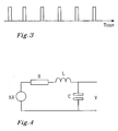
- Each pulse has an amplitude H 0 and a width, a.
- the FFT for the response to such excitation contains all the information available using the previously described response detection in the frequency domain.
- the pulsed magnetic field can be characterised by the field amplitude, H 0 , the width in time, a, when the field is on and the period time, T , of the pulses.
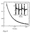
- the duty cycle of the pulse train, a / T is chosen so that the exponential increase of the magnetization (when the field is on) and the exponential decay of the magnetization (when the field is switched off) can be fully seen in the detection time window, as is shown in figure 9 , at least an amount large enough for conducting a relevant analysis. Too fast pulses yield only detection of a small part of the relaxation and to long pulses yield that the magnetization is constant or zero and gives detection of only noise and the signal to noise ratio is decreased.
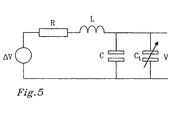
- a typical coil can be represented by the equivalent circuit of Fig. 4 .
- C is the parasitic capacitance between the turns of the insulated wires
- L is coil inductance
- R the resistance of the wire.
- ⁇ V is the induced voltage in the detection coil system according to eq. 1, while V is the output voltage from the detection coil system.
- the resonance frequency can be tuned to the measuring frequency and thereby increase the detection sensitivity.
- the total capacitance is then C t + C and shall replace C in eqs 15 and 16.
- Fig. 6 illustrates a plot of sensitivity is increase (expressed as number times the ordinary sensitivity given by eq. 3) versus the frequency is plotted in the figure below for one specific case.
- L 0 and R 0 is the inductance and resistance of the equivalent circuit without the sample. Since the values attained by the dynamic susceptibility are relative small in this application the inductance and resistance does not change too much. The resonant frequency does not change too much either and this variation can be neglected.
- the FWHM of the resonance is determined mainly by R. It is well known that for a coil that is connected in parallel to the rest of the detection equipment the impedance at resonance, Z res , attains its maximum value and can be much higher then the impedance far away from the resonance, Z ⁇ Z res , as is shown in figure 6 . As discussed above, the resonance frequency of a coil can be tuned using an additional capacitance in parallel with the coil as in Fig. 5 .
- WO 03/019188 describes the procedure of sweeping the frequency of the external magnetic field that is created by the excitation coil and detected the response of the system under investigation differentially, using a system of two suitably wounded detection coils.
- Each detection coil is chosen to be as close to the other one as possible to decrease the off-set voltage (current) that is necessarily created by the electrical mismatch of the two coils, connected in parallel (series) to the rest of the system.
- each coil is designed so that its resonance frequency is far away from the maximum frequency corresponding to the response of investigated system. This has been considered advantageous since the further each coil was from its resonance frequency the smaller was the change in its voltage (current) measured at slightly different frequencies. The result is however that a system induced voltage (current) excursions is very low (for a magnetic particle system with low susceptibility).
- a suitable (but not only) parameter that may be chosen to signal the end of measurement is when measurement at a given frequency has attained a preset S/N ratio. Once the preset ratio has been attained the system should sent a signal that would initiate the change in coil resonant frequency by changing the extra, variable, capacitance, C tune , and a new measurement at a new frequency can start.
- the rate constant k contains information on the stability of the clusters as well as on their mobility and on the probability of reaction given two particles, two clusters, or a cluster and a particle, collide.
- cluster mobility depends on the cluster size the rate of collisions decrease rapidly with cluster sizes and mirrors mainly the collisions between the smallest clusters, i.e., the initial particles. This means that after time t the particle size increased while their number decrease, n ⁇ n 0 , but that the clusters formed are made predominantly from two initial particles (particle-cluster and cluster-cluster collisions are rare compared to particle-particle collisions).
- the appropriate choose is to perform measurement in the time domains since one is able to detect relaxation times much longer then the equivalent frequencies in the frequency domain.
- the lower limit of measurements in the frequency domain is approximately 1Hz which is equivalent to a relaxation time of 1 sec.
- the time domain it is relatively easy to detect relaxation times > 10sec.
- clustering rate may be tailored to correspond to a number (or concentration) of molecules of interest in a solution.
- the description starts from a general situation and then procedures are exemplified by few specific examples. Referring to Fig. 7 , consider a particle 750 with some analyte 752 adsorbed to its surface. The target molecules are denoted 753.
- Clustering may occur if the analyte bound to the particle can form dimers (multimeres) and these additional bonds are exposed towards the outside.
- the particles may form cluster with a cluster formation rate that depends on the analyte coverage.
- the molecules to be detected form multiple bonds 755 with the analyte adsorbed to the particles. If particles with the adsorbed analyte are added to a solution containing an unknown concentration of such target molecules then clusters will be formed where the particles are held together with each other by the bonds mediated via the target molecule.
- the cluster formation rate is in such case a function of the concentration of target molecules in solution.
- the signal does not only depend on the target molecule but also on the concentration of particles in solution and on their size and analyte coverage (among other things). This is actually of value since it allows (among other things) to adjust to some extent the decrease rate and/or the response amplitudes to levels manageable by the measuring equipment used.
- the concentration of a known DNA sequence is required that is characteristic of for example TBC or HIV or other bacterias, cells, etc. It is possible then to extract DNA from the cell or micro-organism, cut into suitable sequence lengths and amplify it. Then it is possible to add to the solution containing the target DNA strands particles covered with suitable complementary single strands, split the double target strands into a single ones and allow the strands on the particles to hybridise with the target strands in solution.
- the agglomeration rate will be a measure of the concentration of such long DNA strands in solution.
- Virtually any antibody based diagnostic procedures require two antibodies: one which catches the target antigen and the second one suitably modified to allow detection that is adsorbed to the catching antibody - antigen complexes. Similar assay can be performed using magnetic nano particles covered with catching antibody and with the detection antibody, respectively. To a solution containing the target antigen, nano particles covered with each kind of antibody are added. The clustering will occur since antigen will be able to form bonds with each type of antibody and thus will hold together particles of each kind.
- FIG. 8a and 8b Another example of the systems 800a and 800b for sample arrangement is shown in figs. 8a and 8b .
- a capillary 840a and 840b is used as a sample 840 holder and a fluidic flow system to deliver the sample to the detection area.
- the sample is injected into a flow as a "plug" 840 of certain width that is determined by the injection time and speed.
- the flow is regulated so that the plug can be stopped at a desired position, for example at the measuring positions 850a, 850b and 860a, 860b. It is also possible to anticipate using several plugs of the same or different materials created by successive injections.
- Fig. 8a shows that different positions/geometries inside the detection coil(s) 810 and 820 are possible while the sample and capillary arrangements in Fig. 8b are similar to aforementioned embodiment
- the plug width, w, as well as the distance between the coil(s) I coil can be varied so that the part of the sample where the measurement is performed is homogeneous and is not subject to intermixing with the rest of the fluid. This is possible given the plug flows under laminar flow since the mixing is then due only to diffusion and is relatively slow.
- the measurement system is calibrated by a two-step routine.
- the system response is measured with an empty sample holder.
- the effect this measurement picks up is the difference in signal when the empty sample holder is in the upper coil to when the sample holder is in the lower coil.
- the difference is attributed to the dielectric properties of the sample holder and the mechanical arm moving the sample holder.
- the second step is performed with a sample containing a material with a known and preferably frequency independent magnetic susceptibility, for instance a paramagnetic material such as Dy 2 O 3 .
- the calibration materials are chosen preferably to have a frequency independent susceptibility in the frequency range used in our sensor system.
- the value of the susceptibility of the calibration material should preferably be in the same range as for the measured sample.
- the geometry and dimensions of the calibration sample should preferably be the same as for the measurement samples, in order to get the correct coupling factor in the detection coil(s).
- the frequency dependency of the gain and the phase between the applied excitation field and the magnetic response from the detection coil(s) is a major concern in construction a high bandwidth susceptometer.
- the frequency dependency of the gain and the phase becomes strong at high frequencies, especially at frequencies close to the resonance frequency of the detection coil(s) or the excitation coil.
- the gain and phase can also become frequency dependent due to the properties of the excitation electronics and/or the detection electronics. The measured sample data will become incorrect, especially at high frequencies, if these effects are not compensated for.
Landscapes
- Physics & Mathematics (AREA)
- Condensed Matter Physics & Semiconductors (AREA)
- General Physics & Mathematics (AREA)
- Spectroscopy & Molecular Physics (AREA)
- Chemical & Material Sciences (AREA)
- Engineering & Computer Science (AREA)
- Nanotechnology (AREA)
- Investigating Or Analyzing Materials By The Use Of Magnetic Means (AREA)
Claims (22)
- Verfahren zum Detektieren von Änderungen eines magnetischen Ansprechverhaltens von mindestens einem Magnetpartikel (250) in einem Trägerfluid, wobei das Verfahren folgendes aufweist:• Verwenden einer Messprozedur, die das Messen der charakteristischen Rotationszeit des Magnetpartikels umfasst, wobei die Messprozedur außerdem das Messen der Brown'schen Relaxation in dem Trägerfluid unter dem Einfluss eines externen Sinus-Erregungs-magnetfeldes oder eines externen gepulsten Erregungs-Magnetfeldes umfasst, und• basierend auf dem Einfluss des externen Sinus-Erregungsmagnet-feldes oder des externen gepulsten Erregungs-Magnetfeldes: Messen des hydrodynamischen Volumens eines Partikels oder der Veränderung des hydrodynamischen Volumens der Partikelveränderung bei Modifikation des effektiven Volumens des Partikels (250) oder
dessen Wechselwirkung mit dem Trägerfluid durch Bestimmen der Veränderung der Magnetisierung des Partikels im Laufe der Zeit,
indem die Veränderung eines Ausgangssignals in einem eine induzierte Differenzspannung detektierenden Detektionsspulensystem (110, 120, 810, 820) überwacht wird, welche von der Veränderung des magnetischen Flusses während eines Zeitraums abhängt, wobei sich die induzierte Differenzspannung eines gut abgeglichenen Detektionsspulensystems wie folgt verhält:
wobei folgendes gilt:
N ist die Windungszahl in zwei identischen Detektionsspulen,
A ist die Querschnittsfläche in den Detektionsspulen,
H ist das Magnetfeld, das von der Erregerspule erzeugt wird,
α ist der magnetische Kopplungsfaktor, und
M ist die Magnetisierung des Partikelsystems. - Verfahren nach Anspruch 1,
wobei dann, wenn ein Sinus-Erregungsfeld verwendet wird, die dynamische Suszeptibilität für ein Magnetpartikelsytem mit einer Brown'schen Relaxationszeit wie folgt angegeben wird:
wobei folgendes gilt:
χo ist die Gleichspannungs-Suszeptibilität,
ω ist die Kreisfrequenz (2πf),
rH ist der hydrodynamische Radius von Partikeln,
f(rH) ist eine Verteilungsfunktion des hydrodynamischen Radius und τ B ist die Brown'sche Relaxationszeit gemäß folgendem Ausdruck:
wobei folgendes gilt:
VH ist das hydrodynamische Volumen,
η ist die Viskosität des Fluids, in dem magnetische Partikel enthalten sind, k B ist die Boltzmannkonstante, und
T ist die Temperatur. - Verfahren nach Anspruch 2,
wobei die Approximation abhängt von den Magnetpartikeln, die eine Anzahl magnetischer Single-Domänen enthalten, und wobei das magnetische Gesamtmoment eine Vektorsumme der einzelnen magnetischen Momente von jeder der Single-Domänen ist. - Verfahren nach Anspruch 1,
wobei die Verteilung der hydrodynamischen Größe des Magnetpartikel-systems bestimmt wird, indem die dynamische Suszeptibilität für ein Magnetpartikelsystem mit einer Brown'schen Relaxationszeit verwendet wird. - Verfahren nach Anspruch 1,
das ferner ein Absorbieren von Molekülen auf einer Partikeloberfläche aufweist, so dass der hydrodynamische Radius der Partikel zunimmt, und wobei dann, wenn die Oberfläche mit Molekülen gesättigt ist, das hydrodynamische Volumen um die Größe einer Hülle zugenommen hat, die eine Dicke aufweist, die das ursprüngliche Partikel umgibt, und wobei sich die Zunahme des hydrodynamischen Radius linear zu der Bedeckung verhält. - Verfahren nach Anspruch 5,
wobei die Brown'sche Relaxationszeit nach der Molekülabsorption wie folgt ausgedrückt wird:
wobei rH der anfängliche hydrodynamische Radius ist, bevor die Partikeloberfläche mit Molekülen bedeckt worden ist, und
wobei die neue dynamische Suszeptibilität wie folgt ausgedrückt wird:
wobei die Brown'sche Relaxationszeit zudem von einer Beschichtung abhängt, die wiederum von einer Analytenkonzentration abhängt. - Vorrichtung (100, 800a, 800b) zum Detektieren eines magnetischen Feld-Ansprechverhaltens oder von Veränderungen eines magnetischen Ansprechverhaltens von mindestens einem Magnetpartikel in einem Trägerfluid, wobei die Detektion das Messen der charakteristischen Rotationszeit der Magnetpartikel umfasst, und wobei das Messen außerdem das Messen der Brown'schen Relaxation in dem Trägerfluid unter dem Einfluss eines externen Sinus-Erregungsmagnetfeldes oder eines externen gepulsten Erregungs-Magnetfeldes umfasst, wobei die Vorrichtung folgendes aufweist: ein Detektionsspulensystem, das eine erste Detektionsspule (110, 810) und eine zweite Detektionsspule (120, 820) aufweist, eine Erregerspule (130) und einen Probenhalter (140),
dadurch gekennzeichnet,
dass die Vorrichtung außerdem folgendes aufweist:Einrichtungen (130), die dazu ausgelegt sind, ein Sinus-Magnetfeld oderein gepulstes Magnetfeld zu erzeugen, und mindestens zwei im wesentlichen identische Detektionsspulen (110, 120, 810, 820), die in gradiometrischer Kopplung mit elektronischen Detektionsschaltungen verbunden sind und dazu ausgelegt sind, die Frequenz zu messen, wobei eine Spannungsdifferenz von einer Windungszahl (N) oder physikalischen Eigenschaften der Detektionsspulen abhängt, und wobei die Erregerspule zum Erzeugen eines Erregungsfeldes (H) ausgestaltet ist und eine Wirkung auf die Signalantwort gemäß folgendem Ausdruck hat:wobei folgendes gilt: N ist die Windungszahl in zwei identischen Detektionsspulen,A ist die Querschnittsfläche in den Detektionsspulen,H ist das Magnetfeld, das von der Erregerspule erzeugt wird,α ist der magnetische Kopplungsfaktor undM ist die Magnetisierung des Partikelsystems.
 - Vorrichtung nach Anspruch 7,
wobei die Erregerspule (130) als Solenoid mit einer bestimmten Länge, einem bestimmten Durchmesser und einer bestimmten Windungszahl der Wicklung gewickelt ist. - Vorrichtung nach Anspruch 7,
wobei das Detektionsspulensystem (110, 120) gemäß einer der folgenden Ausgestaltungen ausgebildet ist:• in einer Form einer gradiometrischen Kopplung erster Ordnung, die im Zentrum der Erregerspule angeordnet ist, oder• in Form von zwei gut abgeglichenen Spulen, die miteinander gekoppelt sind. - Vorrichtung nach Anspruch 7,
wobei das Detektionsspulensystem den Wert der magnetischen Flussdifferenz zwischen den zwei Spulen detektiert. - Vorrichtung nach Anspruch 7,
wobei das Detektionsspulensystem derart ausgebildet ist, dass zwei abgeglichene Spulen mit ihren Längsachsen im wesentlichen parallel zu der Längsachse der Erregerspule angeordnet sind. - Vorrichtung nach Anspruch 7,
wobei die Detektionsspulen folgendermaßen gewickelt sind:• entweder in zwei unterschiedlichen Richtungen, d. h. im Uhrzeigersinn und gegen den Uhrzeigersinn, und in Reihe miteinander verbunden,• oder in den gleichen Richtungen, jedoch derart miteinander verbunden, dass die induzierten Spannungen in den zwei Spulen in entgegengesetzten Richtungen anliegen. - Vorrichtung nach Anspruch 7,
wobei ein magnetisches Signal zunächst mit einer Messung mit einer Probe in einer der Spulen und dann in einer weiteren Messung mit der Probe in der anderen Spule gemessen wird. - Vorrichtung nach Anspruch 7,
wobei die Gesamtspannung, die dann detektiert wird, wenn die Probe in der ersten Spule ist, V1 + Vbackground beträgt, und wobei die Gesamtspannung, die dann detektiert wird, wenn die Probe in der zweiten Spule ist, -V2 + Vbackground beträgt, und wobei die Differenz der zwei Messergebnisse V1 + V2 beträgt, so dass ein Störpegel beseitigt wird, und wobei der Mittelwert von V1 + V2 ein Signal von der Probe repräsentiert. - Vorrichtung nach Anspruch 7,
wobei ein externes Sinus-Magnetfeld oder externes gepulstes Magnetfeld an das gleiche Partikelsystem angelegt wird, und wobei die Magnetisierung der Partikel im Zeitbereich gemessen wird, indem entweder der Anstieg der Magnetisierung unmittelbar nach dem Anlegen des Pulses gemessen wird, oder indem das Abfallen der Magnetisierung nach dem Abschalten des Pulses oder nachdem ein externes Sinus-Magnetfeld oder externes gepulstes Magnetfeld an das gleiche Partikelsystem angelegt worden ist, gemessen wird, und wobei die Magnetisierung der Partikel ansteigt, wenn das Feld angelegt wird, und exponentiell abfällt, wenn das Feld entfernt wird, so dass das exponentielle Verhalten charakteristisch für die Relaxationszeit ist, die proportional zum Kehrwert der Brown'schen Relaxationsfrequenz ist. - Vorrichtung nach Anspruch 15,
wobei die Frequenz eines Messfeldes nicht abgefahren wird, sondern wobei die gleiche Information dadurch erhalten wird, dass eine Fourier-Transformation der Relaxation des magnetischen Ansprechverhaltens im Zeitbereich vorgenommen wird, und wobei die Information ein frequenzabhängiges magnetisches Ansprechverhalten ist. - Vorrichtung nach Anspruch 15,
wobei die induzierte Differenzspannung im Falle des gepulsten magnetischen Feldes wie folgt ausgedrückt wird:
wenn das Feld eingeschaltet ist, und:
wenn das Erregungsfeld ausgeschaltet ist. - Vorrichtung nach Anspruch 17,
wobei die Verteilung der hydrodynamischen Größe des Magnetpartikelsystems bestimmt wird, indem die induzierte Spannung gemessen wird, und zwar sowohl dann, wenn das Feld eingeschaltet ist, als auch dann, wenn das Feld ausgeschaltet ist, und wobei die Einschaltdauer der Pulsfolge (a/T) derart gewählt ist, dass das exponentielle Ansteigen der Magnetisierung, wenn das Feld eingeschaltet ist, und das exponentielle Abfallen der Magnetisierung, wenn das Feld ausgeschaltet ist, vollständig in dem Zeitfenster für die Detektion detektiert wird. - Vorrichtung nach Anspruch 7,
die eine oder mehrere der nachfolgenden Komponenten aufweist:• eine durchstimmbare Kapazität (Ct ), die in Parallelschaltung mit einer Kapazität des Systems verbunden ist,• eine Kapillare als Probenhalter und ein Fluidströmungssystem zum Zuführen der Probe zu einem Detektionsbereich,• eine Einrichtung zum Regulieren der Strömung, so dass die Anordnung an einer gewünschten Position, wie beispielsweise einer Messposition, angehalten werden kann,• eine Einrichtung zum Verwenden mehrerer Anordnungen von gleichen oder verschiedenartigen Materialien, die durch aufeinanderfolgende Injektionen erzeugt werden. - Vorrichtung nach Anspruch 7,
wobei die Resonanzfrequenz von jeder Spule auf eine Messfrequenz abgestimmt wird. - Vorrichtung nach Anspruch 20,
wobei die Probe in einer Strömung injiziert wird, die einen Aufbau mit einer Breite bildet, die durch die Injektionszeit und die Injektionsgeschwindigkeit bestimmt ist. - Verfahren zum Kalibrieren eines Systems
nach einem der Ansprüche 7 bis 21,
wobei das Verfahren folgendes aufweist:• einen ersten Verfahrensschritt, in welchem das System-Ansprech-verhalten mit einem leeren Probenhalter gemessen wird,• einen zweiten Verfahrensschritt, in welchem eine Differenz berechnet wird, und zwar zwischen dem Signal, wenn sich der leere Probenhalter in der ersten Spule befindet, und dem Signal, wenn sich der Probenhalter in der zweiten Spule befindet,• einen dritten Verfahrensschritt, in welchem das System gemessen wird, und zwar mit einer Probe, die ein Material mit einer bekannten und vorzugsweise frequenzabhängigen magnetischen Suszeptibilität enthält; und• Kalibrieren des Systems basierend auf diesen Messungen.
Applications Claiming Priority (2)
| Application Number | Priority Date | Filing Date | Title |
|---|---|---|---|
| SE0600870A SE529474C2 (sv) | 2006-04-19 | 2006-04-19 | Detekteringsanordning och förfarande |
| PCT/SE2007/000314 WO2007120095A1 (en) | 2006-04-19 | 2007-04-04 | Detection device and method |
Publications (3)
| Publication Number | Publication Date |
|---|---|
| EP2016413A1 EP2016413A1 (de) | 2009-01-21 |
| EP2016413A4 EP2016413A4 (de) | 2012-01-25 |
| EP2016413B1 true EP2016413B1 (de) | 2013-09-25 |
Family
ID=38370538
Family Applications (1)
| Application Number | Title | Priority Date | Filing Date |
|---|---|---|---|
| EP07747980.6A Ceased EP2016413B1 (de) | 2006-04-19 | 2007-04-04 | Erfassungsvorrichtung und -verfahren |
Country Status (5)
| Country | Link |
|---|---|
| US (1) | US8624584B2 (de) |
| EP (1) | EP2016413B1 (de) |
| JP (1) | JP2009534649A (de) |
| SE (1) | SE529474C2 (de) |
| WO (1) | WO2007120095A1 (de) |
Families Citing this family (34)
| Publication number | Priority date | Publication date | Assignee | Title |
|---|---|---|---|---|
| US8697029B2 (en) | 2002-04-18 | 2014-04-15 | The Regents Of The University Of Michigan | Modulated physical and chemical sensors |
| US9068977B2 (en) | 2007-03-09 | 2015-06-30 | The Regents Of The University Of Michigan | Non-linear rotation rates of remotely driven particles and uses thereof |
| US9097644B2 (en) * | 2007-08-17 | 2015-08-04 | Massachusetts Institute Of Technology | Magnetic resonance-based viscometers and methods |
| SE534842C2 (sv) * | 2010-05-26 | 2012-01-17 | Imego Ab | Spole innefattande lindning bestående av en multi-axialkabel |
| WO2012027747A2 (en) | 2010-08-27 | 2012-03-01 | The Regents Of The University Of Michigan | Asynchronous magnetic bead rotation sensing systems and methods |
| US20140099663A1 (en) * | 2010-11-15 | 2014-04-10 | Regents Of The University Of Minnesota | Gmr sensor |
| US9074976B2 (en) * | 2011-03-01 | 2015-07-07 | Stc.Unm | Viscosity measuring method |
| WO2012142179A2 (en) | 2011-04-11 | 2012-10-18 | The Regents Of The University Of Michigan | Magnetically induced microspinning for super-detection and super-characterization of biomarkers and live cells |
| EP2541230A1 (de) | 2011-06-30 | 2013-01-02 | Koninklijke Philips Electronics N.V. | Erkennung von Clustern aus magnetischen Partikeln |
| GB201115120D0 (en) * | 2011-09-01 | 2011-10-19 | Univ Exeter | Method and device for detecting an analyte |
| EP2780692A1 (de) * | 2011-11-14 | 2014-09-24 | Koninklijke Philips N.V. | Vorrichtung zur clustererkennung |
| US9797817B2 (en) | 2012-05-03 | 2017-10-24 | The Regents Of The University Of Michigan | Multi-mode separation for target detection |
| US9928988B2 (en) * | 2013-03-13 | 2018-03-27 | Varian Semiconductor Equipment Associates, Inc. | Ion source |
| US9176000B2 (en) * | 2013-04-15 | 2015-11-03 | General Electric Company | System for measurement of fluid levels in multi-phase fluids |
| US9983110B2 (en) | 2013-11-04 | 2018-05-29 | The Regents Of The University Of Michigan | Asynchronous magnetic bead rotation (AMBR) microviscometer for analysis of analytes |
| DE102015205202B4 (de) * | 2015-03-23 | 2026-01-08 | Bundesrepublik Deutschland, vertr. durch das Bundesministerium für Wirtschaft und Energie, dieses vertreten durch den Präsidenten der Physikalisch-Technischen Bundesanstalt | Verfahren zum Messen einer magnetischen Eigenschaft von magnetischen Nanopartikeln |
| US10809228B2 (en) * | 2015-06-25 | 2020-10-20 | Kawano Lab. Inc. | Method and apparatus for quantitatively evaluating amount of dispersion medium adsorbed to dispersoid particles |
| GB201522661D0 (en) * | 2015-12-22 | 2016-02-03 | Univ Sheffield | Apparatus and methods for determining electrical conductivity of tissue |
| CA3030308C (en) | 2016-07-29 | 2022-04-05 | The Board Of Trustees Of Western Michigan University | Magnetic nanoparticle-based gyroscopic sensor |
| CN109060163A (zh) * | 2018-09-04 | 2018-12-21 | 华中科技大学 | 一种用于电磁加热设备的磁纳米粒子电感测温方法及装置 |
| US20220178918A1 (en) * | 2019-03-20 | 2022-06-09 | Citizen Watch Co., Ltd. | Device for detecting substance to be measured, and method for detecting substance to be measured |
| JP7269838B2 (ja) * | 2019-09-02 | 2023-05-09 | 株式会社日立製作所 | 応力分布計測装置および応力分布計測方法 |
| US12287388B2 (en) | 2020-04-16 | 2025-04-29 | Mitsubishi Electric Corporation | Magnetic particle imaging device |
| CN111624542B (zh) * | 2020-05-29 | 2022-05-27 | 南京理工大学 | 一种脉冲磁场测量系统的频率响应标定方法 |
| CN113009388B (zh) * | 2021-03-19 | 2022-02-22 | 北京科技大学 | 一种磁性液体磁化弛豫时间测量装置及方法 |
| CN114264555B (zh) * | 2021-12-29 | 2023-09-12 | 中国科学院合肥物质科学研究院 | 一种超导线应变分布状态的测量装置与测量方法 |
| JP2023134959A (ja) * | 2022-03-15 | 2023-09-28 | 国立大学法人東北大学 | 抗原検出装置及び抗原検出方法 |
| CN115166606B (zh) * | 2022-06-06 | 2024-12-06 | 中国人民解放军国防科技大学 | 一种水动力学扰动激发德拜磁场的试验系统与试验方法 |
| CN116338538B (zh) * | 2022-08-24 | 2024-05-10 | 北京易动宇航科技有限公司 | 基于特征识别的直流电磁铁响应时间识别方法 |
| CN115568841B (zh) * | 2022-09-27 | 2023-04-14 | 北京航空航天大学 | 一种基于尼尔弛豫的磁纳米粒子检测与成像方法 |
| CN115718273B (zh) * | 2022-11-18 | 2024-04-19 | 华中科技大学 | 一种基于磁感应强度测量物体磁化率的装置及其测量方法 |
| CN117598680B (zh) * | 2024-01-23 | 2024-05-07 | 辽宁嘉玉科技有限公司 | 磁粒子磁化感知距离测量装置与方法 |
| CN117929217A (zh) * | 2024-03-22 | 2024-04-26 | 宁德时代新能源科技股份有限公司 | 磁性颗粒含量的检测系统以及检测方法 |
| CN118409255B (zh) * | 2024-07-02 | 2024-08-27 | 华中科技大学 | 一种用于脉冲强磁场下的磁化测量传感器 |
Family Cites Families (9)
| Publication number | Priority date | Publication date | Assignee | Title |
|---|---|---|---|---|
| DD111360A5 (de) | 1974-04-11 | 1975-02-12 | ||
| DE19503664C2 (de) | 1995-01-27 | 1998-04-02 | Schering Ag | Magnetorelaxometrische Detektion von Analyten |
| DE19938384A1 (de) * | 1999-08-06 | 2001-02-15 | Diagnostikforschung Inst | Verfahren zur Detektion von Bindungsreaktionen mittels Messung der Relaxation der Doppelbrechung magnetischer Teilchen |
| US6979574B1 (en) * | 1999-08-06 | 2005-12-27 | Institut Fuer Diagnostik Forshung Gmbh | Process for detecting binding reactions with use of the measurement of the relaxation of the double refraction of magnetic particles |
| WO2001011360A2 (de) * | 1999-08-06 | 2001-02-15 | Institut für Diagnostikforschung GmbH an der Freien Universität Berlin | Relaxation der doppelbrechung magnetischer nanopartikel während bindungsreaktionen |
| WO2003019188A1 (en) * | 2001-08-31 | 2003-03-06 | Imego Ab | Methdo and arrangement for analyzing substances |
| US20030076087A1 (en) * | 2001-08-31 | 2003-04-24 | Imego Ab | Method and arrangement relating to substance analysis |
| EP1751534A1 (de) * | 2004-05-18 | 2007-02-14 | Koninklijke Philips Electronics N.V. | Magnetische rotation zur verbesserung des signal/rausch-verhältnisses beim biosensing |
| JP5205807B2 (ja) * | 2007-05-17 | 2013-06-05 | 株式会社日立製作所 | 磁気信号計測装置 |
-
2006
- 2006-04-19 SE SE0600870A patent/SE529474C2/sv not_active IP Right Cessation
-
2007
- 2007-04-04 WO PCT/SE2007/000314 patent/WO2007120095A1/en not_active Ceased
- 2007-04-04 JP JP2009506441A patent/JP2009534649A/ja active Pending
- 2007-04-04 EP EP07747980.6A patent/EP2016413B1/de not_active Ceased
-
2008
- 2008-10-20 US US12/254,288 patent/US8624584B2/en not_active Expired - Fee Related
Also Published As
| Publication number | Publication date |
|---|---|
| SE0600870L (sv) | 2007-08-21 |
| US20090085557A1 (en) | 2009-04-02 |
| EP2016413A4 (de) | 2012-01-25 |
| US8624584B2 (en) | 2014-01-07 |
| JP2009534649A (ja) | 2009-09-24 |
| EP2016413A1 (de) | 2009-01-21 |
| WO2007120095A1 (en) | 2007-10-25 |
| SE529474C2 (sv) | 2007-08-21 |
Similar Documents
| Publication | Publication Date | Title |
|---|---|---|
| EP2016413B1 (de) | Erfassungsvorrichtung und -verfahren | |
| US6825655B2 (en) | Method and arrangement for detecting changes of a magnetic response in magnetic particles | |
| EP1421382B1 (de) | Verfahren und anordnung zur analyse von substanzen | |
| RU2460058C2 (ru) | Измерение параметров агглютинации | |
| Tamanaha et al. | Magnetic labeling, detection, and system integration | |
| Tanner et al. | Restricted self‐diffusion of protons in colloidal systems by the pulsed‐gradient, spin‐echo method | |
| US7432714B2 (en) | Method and device for on-chip magnetic resonance spectroscopy | |
| US9176206B2 (en) | Effective-inductance-change based magnetic particle sensing | |
| US20030076087A1 (en) | Method and arrangement relating to substance analysis | |
| US10197564B2 (en) | Nuclear magnetic resonance apparatus and methods | |
| US7560289B2 (en) | Methods of quantitatively measuring biomolecules | |
| CN101627297B (zh) | 测量凝集参数 | |
| Tsukada et al. | Using magnetic field gradients to shorten the antigen-antibody reaction time for a magnetic immunoassay | |
| RU2471170C2 (ru) | Способ и устройство для анализа магнитного материала и анализатор, содержащий это устройство | |
| US20160025825A1 (en) | Nuclear magnetic resonance apparatus and methods | |
| Østerberg et al. | On-chip measurements of Brownian relaxation of magnetic beads with diameters from 10 nm to 250 nm | |
| US10094897B2 (en) | Nuclear magnetic resonance apparatus and methods | |
| Makiranta et al. | Modeling and simulation of magnetic nanoparticle sensor | |
| Østerberg et al. | On-chip Brownian relaxation measurements of magnetic nanobeads in the time domain | |
| Sun et al. | A multi-frequency magnetic particle spectroscopy system for the characterization of magnetic nanoparticles | |
| Westergaard Østerberg et al. | On-chip measurements of Brownian relaxation vs. concentration of 40 nm magnetic beads | |
| SE524094C2 (sv) | Metod och anordning avseende analys av magnetiska partiklar | |
| Amouzegar et al. | Application of magnetic nanomaterials in magnetic field | |
| SE522170C2 (sv) | Metod och anordning för detektering av förändringar av magnetisk respons hos magnetiska partiklar försedda med yttre skikt i bärarvätska | |
| GROPPI | Integrated optical biosensing assays exploiting magnetic labels |
Legal Events
| Date | Code | Title | Description |
|---|---|---|---|
| PUAI | Public reference made under article 153(3) epc to a published international application that has entered the european phase |
Free format text: ORIGINAL CODE: 0009012 |
|
| 17P | Request for examination filed |
Effective date: 20081119 |
|
| AK | Designated contracting states |
Kind code of ref document: A1 Designated state(s): AT BE BG CH CY CZ DE DK EE ES FI FR GB GR HU IE IS IT LI LT LU LV MC MT NL PL PT RO SE SI SK TR |
|
| AX | Request for extension of the european patent |
Extension state: AL BA HR MK RS |
|
| RIN1 | Information on inventor provided before grant (corrected) |
Inventor name: PETTERSSON, KAROLINA Inventor name: ILVER, DAG Inventor name: PRIETO-ASTALAN, ANDREA Inventor name: BLOMGREN, JAKOB Inventor name: JOHANSSON, CHRISTER Inventor name: JONASSON, CHRISTIAN Inventor name: KROZER, ANATOL |
|
| RIN1 | Information on inventor provided before grant (corrected) |
Inventor name: ILVER, DAG Inventor name: KROZER, ANATOL Inventor name: PRIETO-ASTALAN, ANDREA Inventor name: PETTERSSON, KAROLINA Inventor name: JONASSON, CHRISTIAN Inventor name: BLOMGREN, JAKOB Inventor name: JOHANSSON, CHRISTER |
|
| RIN1 | Information on inventor provided before grant (corrected) |
Inventor name: JONASSON, CHRISTIAN Inventor name: JOHANSSON, CHRISTER Inventor name: KROZER, ANATOL Inventor name: ILVER, DAG Inventor name: PRIETO-ASTALAN, ANDREA Inventor name: BLOMGREN, JAKOB Inventor name: PETTERSSON, KAROLINA |
|
| DAX | Request for extension of the european patent (deleted) | ||
| RBV | Designated contracting states (corrected) |
Designated state(s): DE FR GB |
|
| A4 | Supplementary search report drawn up and despatched |
Effective date: 20111222 |
|
| RIC1 | Information provided on ipc code assigned before grant |
Ipc: G01R 33/12 20060101ALI20111216BHEP Ipc: G01R 33/16 20060101ALI20111216BHEP Ipc: G01R 33/02 20060101ALI20111216BHEP Ipc: G01N 33/543 20060101AFI20111216BHEP |
|
| GRAJ | Information related to disapproval of communication of intention to grant by the applicant or resumption of examination proceedings by the epo deleted |
Free format text: ORIGINAL CODE: EPIDOSDIGR1 |
|
| GRAP | Despatch of communication of intention to grant a patent |
Free format text: ORIGINAL CODE: EPIDOSNIGR1 |
|
| RIN1 | Information on inventor provided before grant (corrected) |
Inventor name: BLOMGREN, JAKOB Inventor name: KROZER, ANATOL Inventor name: JONASSON, CHRISTIAN Inventor name: PRIETO-ASTALAN, ANDREA Inventor name: PETTERSSON, KAROLINA Inventor name: JOHANSSON, CHRISTER Inventor name: ILVER, DAG |
|
| GRAJ | Information related to disapproval of communication of intention to grant by the applicant or resumption of examination proceedings by the epo deleted |
Free format text: ORIGINAL CODE: EPIDOSDIGR1 |
|
| GRAP | Despatch of communication of intention to grant a patent |
Free format text: ORIGINAL CODE: EPIDOSNIGR1 |
|
| INTG | Intention to grant announced |
Effective date: 20130719 |
|
| RIN1 | Information on inventor provided before grant (corrected) |
Inventor name: PRIETO-ASTALAN, ANDREA Inventor name: JONASSON, CHRISTIAN Inventor name: BLOMGREN, JAKOB Inventor name: KROZER, ANATOL Inventor name: PETTERSSON, KAROLINA Inventor name: JOHANSSON, CHRISTER Inventor name: ILVER, DAG |
|
| GRAS | Grant fee paid |
Free format text: ORIGINAL CODE: EPIDOSNIGR3 |
|
| GRAA | (expected) grant |
Free format text: ORIGINAL CODE: 0009210 |
|
| RAP1 | Party data changed (applicant data changed or rights of an application transferred) |
Owner name: ACREO SWEDISH ICT AB |
|
| AK | Designated contracting states |
Kind code of ref document: B1 Designated state(s): DE FR GB |
|
| REG | Reference to a national code |
Ref country code: GB Ref legal event code: FG4D |
|
| REG | Reference to a national code |
Ref country code: DE Ref legal event code: R096 Ref document number: 602007033035 Country of ref document: DE Effective date: 20131128 |
|
| REG | Reference to a national code |
Ref country code: DE Ref legal event code: R097 Ref document number: 602007033035 Country of ref document: DE |
|
| PLBE | No opposition filed within time limit |
Free format text: ORIGINAL CODE: 0009261 |
|
| STAA | Information on the status of an ep patent application or granted ep patent |
Free format text: STATUS: NO OPPOSITION FILED WITHIN TIME LIMIT |
|
| 26N | No opposition filed |
Effective date: 20140626 |
|
| REG | Reference to a national code |
Ref country code: DE Ref legal event code: R097 Ref document number: 602007033035 Country of ref document: DE Effective date: 20140626 |
|
| REG | Reference to a national code |
Ref country code: FR Ref legal event code: PLFP Year of fee payment: 9 |
|
| REG | Reference to a national code |
Ref country code: FR Ref legal event code: PLFP Year of fee payment: 10 |
|
| REG | Reference to a national code |
Ref country code: FR Ref legal event code: PLFP Year of fee payment: 11 |
|
| REG | Reference to a national code |
Ref country code: FR Ref legal event code: PLFP Year of fee payment: 12 |
|
| PGFP | Annual fee paid to national office [announced via postgrant information from national office to epo] |
Ref country code: FR Payment date: 20230316 Year of fee payment: 17 |
|
| PGFP | Annual fee paid to national office [announced via postgrant information from national office to epo] |
Ref country code: GB Payment date: 20230316 Year of fee payment: 17 |
|
| PGFP | Annual fee paid to national office [announced via postgrant information from national office to epo] |
Ref country code: DE Payment date: 20230317 Year of fee payment: 17 |
|
| REG | Reference to a national code |
Ref country code: DE Ref legal event code: R119 Ref document number: 602007033035 Country of ref document: DE |
|
| GBPC | Gb: european patent ceased through non-payment of renewal fee |
Effective date: 20240404 |
|
| PG25 | Lapsed in a contracting state [announced via postgrant information from national office to epo] |
Ref country code: DE Free format text: LAPSE BECAUSE OF NON-PAYMENT OF DUE FEES Effective date: 20241105 |
|
| PG25 | Lapsed in a contracting state [announced via postgrant information from national office to epo] |
Ref country code: GB Free format text: LAPSE BECAUSE OF NON-PAYMENT OF DUE FEES Effective date: 20240404 |
|
| PG25 | Lapsed in a contracting state [announced via postgrant information from national office to epo] |
Ref country code: FR Free format text: LAPSE BECAUSE OF NON-PAYMENT OF DUE FEES Effective date: 20240430 |
|
| PG25 | Lapsed in a contracting state [announced via postgrant information from national office to epo] |
Ref country code: GB Free format text: LAPSE BECAUSE OF NON-PAYMENT OF DUE FEES Effective date: 20240404 Ref country code: FR Free format text: LAPSE BECAUSE OF NON-PAYMENT OF DUE FEES Effective date: 20240430 Ref country code: DE Free format text: LAPSE BECAUSE OF NON-PAYMENT OF DUE FEES Effective date: 20241105 |